
Related Manuals for Gira 5142 00


Summary of Contents for Gira 5142 00
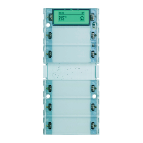
- Page 1 Product documentation Issue: 23.03.2017 51423400 Push button sensor 3 Plus 2-gang Push button sensor 3 Plus 5-gang (2+3) Order No. 5142 00 Order No. 5145 00...
-
Page 2: Table Of Contents
4.2.4.2 Room temperature controller ............... 4.2.4.2.1 Operating modes and operating mode change-over ......4.2.4.2.2 Control algorithms and calculation of command values ....... 4.2.4.2.3 Adapting the control algorithms ............Order No. 5142 00 Page 2 of 281 Order No. 5145 00... - Page 3 Parameters on the push button sensor function section ......4.2.5.3 Parameter for the controller function section ..........4.2.5.4 Parameter on scene function ............... 4.2.5.5 Parameters for the display ................Appendix ........................... Index ........................... Order No. 5142 00 Page 3 of 281 Order No. 5145 00...
-
Page 4: Product Definition
Design: UP (concealed) Order No. 5142 00 / 5145 00 1.2 Function The push button sensor 3 plus combines the functions of a KNX/EIB single-room temperature controller, a push button sensor and a display unit in just one bus subscriber. The combination of these functions makes it possible, for example, to control the light, the blinds, and the room temperature centrally from the entry area of a room. - Page 5 Alternatively, communication object control can be used to change the brightness of all status LEDs, the labelling field illumination and the backlighting of the display. This makes it possible, Order No. 5142 00 Page 5 of 281 Order No. 5145 00...
- Page 6 KNX / EIB actuators can be controlled in up to 8 scenes via up to 8 outputs by means of switching or value commands. Order No. 5142 00 Page 6 of 281 Order No. 5145 00...
-
Page 7: Accessories
Inscription sheet Order No. 1090 00 Inscription sheet Order No. 1089 00 Rocker set 2-gang plus Order No. 2142 .. Rocker set 5-gang plus Order No. 2145 .. Order No. 5142 00 Page 7 of 281 Order No. 5145 00... -
Page 8: Installation, Electrical Connection And Operation
A minimum distance of at least 4 mm must be maintained between bus conductors and mains voltage cores. The device may not be opened or operated outside the technical specifications. Order No. 5142 00 Page 8 of 281 Order No. 5145 00... -
Page 9: Device Components
Neutral inscription panels are included with the devices as part of the scope of supply. If necessary, individual labels can be created using optionally available labelling sheets (see Accessories) and labelling software, or on the Internet at marking.gira.com. Order No. 5142 00 Page 9 of 281 Order No. -
Page 10: Fitting And Electrical Connection
Screw the push button sensor cover to the supporting frame of the bus coupling unit. Use the screw (9) provided. Order No. 5142 00 Page 10 of 281 Order No. 5145 00... - Page 11 (10) Screw and anchor set for mechanical fastening and for anti-theft protection (included with the push button sensor cover) (11) Inscription panel (12) Rocker cover (13) Central web Order No. 5142 00 Page 11 of 281 Order No. 5145 00...
- Page 12 If necessary, label the inscription signs. Optionally the separately available labelling sheets (see Accessories) can be used. Finally, mount the rocker covers, the central web (13) together with the labelling panel by snapping them on. Order No. 5142 00 Page 12 of 281 Order No. 5145 00...
- Page 13 Installation, electrical connection and operation i Before final fitting of the rocker covers, the physical address has to be loaded into the device (see page 14). Order No. 5142 00 Page 13 of 281 Order No. 5145 00...
-
Page 14: Commissioning
If the device was programmed with incorrect application data, then backillumination of the labelling field flashes slowly. In this case, the device will not function after start-up. Order No. 5142 00 Page 14 of 281 Order No. 5145 00... -
Page 15: Operation
In the push button function either a control surface is divided into 2 functionally separate actuation pressure points (2 buttons), or a control surface is evaluated as Order No. 5142 00 Page 15 of 281 Order No. 5145 00... -
Page 16: Basic Display
"Display" in this documentation (see page 181). Figure 6: Example of a basic display with two display areas (Time, setpoint temperature, room temperature, fan level display) Order No. 5142 00 Page 16 of 281 Order No. 5145 00... - Page 17 Installation, electrical connection and operation Figure 7: Example of a basic display with one display area (Room temperature, operating mode display) Order No. 5142 00 Page 17 of 281 Order No. 5145 00...
-
Page 18: Menu "Setpoint
I05 or higher. On older devices with earlier release codes, application is only ever possible with OK, no matter how the parameter for setpoint confirmation is set. Order No. 5142 00 Page 18 of 281 Order No. 5145 00... - Page 19 "Setpoint" is active, then the display shows the message "The setting has been discarded". After that the menu is automatically exited. In this case the settings configured via the menu are discarded! Order No. 5142 00 Page 19 of 281 Order No. 5145 00...
-
Page 20: Menu "Settings
The main menu can be exited by selecting and confirming the entry "Abort". Alternatively the main menu will be exited if no further input is made for approx. 15 seconds. Order No. 5142 00 Page 20 of 281 Order No. 5145 00... - Page 21 "Setpoint. temp cool" can be hidden temporarily. If controller operation is disabled via the bus while the configuration menu is still active on the device, then when disabled controller settings Order No. 5142 00 Page 21 of 281 Order No. 5145 00...
- Page 22 The menu "Fan controller" can be used to switch the fan level of a fan coil, if present, up or down in steps, if it controlled by a Gira KNX/EIB fan coil actuator (order no. 2163 00). In operation, a distinction is made between the automatic mode and the manual operation of the fan coil.
- Page 23 Installation, electrical connection and operation i To control a fan coil, the push button sensor 3 plus must be connected with a Gira KNX/EIB fan coil actuator via various communication objects. It is also important to adapt the parameterisation of the fan coil actuator to the functions of the push button sensor. A more detailed description of the manual fan control and the necessary device configuration can be found in the chapter "Display"...
- Page 24 "Heat"). When controller operation is disabled, the menus "Setpnt.temp heat" and "Setpoint. temp cool" are not visible. i The menus "Setpnt temp heat" and "Setpoint. temp cool" are not visible on controller extensions. Order No. 5142 00 Page 24 of 281 Order No. 5145 00...
- Page 25 ETS. i With two control circuits with separate setpoints, the configuration menu can only be used to setpoint temperatures of the first control circuit. Order No. 5142 00 Page 25 of 281 Order No. 5145 00...
- Page 26 The menu "Set heat.tim" (Figure 13) can be used to edit existing entries or to create new switching times, so long as there are free memory slots. Order No. 5142 00 Page 26 of 281 Order No. 5145 00...
- Page 27 In each of these steps it is possible to select the available Order No. 5142 00 Page 27 of 281...
- Page 28 In this case the push button sensor only executes the switching time with the highest switching time number. The menu "Del heat.tim" (Figure 14) can be used to delete existing entries. Order No. 5142 00 Page 28 of 281 Order No. 5145 00...
- Page 29 ETS. Disabling the heating timer via the bus has no effect on the visibility of the heating timer submenu. The menus "Set heat tim" and "Del heat.tim" are not visible on controller extensions. Order No. 5142 00 Page 29 of 281 Order No. 5145 00...
- Page 30 ETS programming operation. A device reset due to a bus voltage failure does not reset the contrast set in the menu. Order No. 5142 00 Page 30 of 281 Order No. 5145 00...
-
Page 31: Technical Data
420 mW (Via bus coupler 3) Connection mode 10 pole male connector strip Temperature sensor Measuring range internal temperature sensor 0 ... 40 °C Measuring range wired remote temperature 0 ... 50 °C sensor Order No. 5142 00 Page 31 of 281 Order No. 5145 00... -
Page 32: Software Description
& push button sensor 3 plus 5-gang for ETS3.0 application with display. 10E511 Version d 5 control surfaces for button sensor onwards function and 1 display operating rocker and ETS4 switch. Order No. 5142 00 Page 32 of 281 Order No. 5145 00... - Page 33 Configurable behaviour when accepting a setpoint shift set locally on the device (application with or without OK). Order No. 5142 00 Page 33 of 281 Order No. 5145 00...
-
Page 34: Software "Push Button Sensor 3 Plus
The rockers or buttons can be disabled via a 1-bit object. During an active disable, all or some of the rockers / buttons can have no function, can perform the function of a selected button or execute one of two presettable disabling functions. Order No. 5142 00 Page 34 of 281 Order No. 5145 00... - Page 35 Full-featured indication of the controller status on the display of the extension (heating / cooling reporting, setpoint shift, room temperature, setpoint temperature and current operating mode). Room temperature measurement also possible on the extension. Order No. 5142 00 Page 35 of 281 Order No. 5145 00...
- Page 36 64 scenes can be recalled and stored. Order No. 5142 00 Page 36 of 281 Order No. 5145 00...
-
Page 37: Notes On Software
Plugging the pushbutton sensor onto a flush-mounted bus coupling unit 1 or 2 (older generation) is not possible in some cases, and generally not intended, and as a result the device combination will not function. Order No. 5142 00 Page 37 of 281 Order No. 5145 00... -
Page 38: Object Table
3: For reading, the R-flag must be set. The last value written to the object via the bus or by the device will be read. Order No. 5142 00 Page 38 of 281 Order No. 5145 00... - Page 39 3: For reading, the R-flag must be set. The last value written to the object via the bus or by the device will be read. Order No. 5142 00 Page 39 of 281 Order No. 5145 00...
- Page 40 3: For reading, the R-flag must be set. The last value written to the object via the bus or by the device will be read. Order No. 5142 00 Page 40 of 281 Order No. 5145 00...
- Page 41 3: For reading, the R-flag must be set. The last value written to the object via the bus or by the device will be read. Order No. 5142 00 Page 41 of 281 Order No. 5145 00...
- Page 42 1: The number of status LEDs depends on the configured device variant. 2: For reading, the R-flag must be set. The last value written to the object via the bus will be read. Order No. 5142 00 Page 42 of 281 Order No. 5145 00...
- Page 43 1: The number of status LEDs depends on the configured device variant. 2: For reading, the R-flag must be set. The last value written to the object via the bus will be read. Order No. 5142 00 Page 43 of 281 Order No. 5145 00...
- Page 44 1: For reading, the R-flag must be set. The last value written to the object via the bus will be read. Order No. 5142 00 Page 44 of 281 Order No. 5145 00...
- Page 45 1-byte object for the transmission of value telegrams, if 2-channel operation is activated. 1: For reading, the R-flag must be set. The last value written to the object via the bus will be read. Order No. 5142 00 Page 45 of 281 Order No. 5145 00...
- Page 46 1-bit object by means of which the push button sensor can be disabled and enabled again (polarity configurable). 1: For reading, the R-flag must be set. The last value written to the object via the bus will be read. Order No. 5142 00 Page 46 of 281 Order No. 5145 00...
- Page 47 1: For reading, the R-flag must be set. The last value written to the object via the bus will be read. 2: For reading, the R-flag must be set. The last value written to the object via the bus or by the device will be read. Order No. 5142 00 Page 47 of 281 Order No. 5145 00...
- Page 48 1: For reading, the R-flag must be set. The last value written to the object via the bus or by the device will be read. Order No. 5142 00 Page 48 of 281 Order No. 5145 00...
- Page 49 The temperature value must always be output in the format "°C". 1: For reading, the R-flag must be set. The last value written to the object via the bus will be read. Order No. 5142 00 Page 49 of 281 Order No. 5145 00...
- Page 50 2: For reading, the R-flag must be set. The last value written to the object via the bus will be read. 3: Scene outputs 2 … 8 see scene output 1, shift of the object number (66 + number of scene output - 1). Order No. 5142 00 Page 50 of 281 Order No. 5145 00...
- Page 51 1-byte object with which one of the eight internally stored scenes can be recalled or stored again. 1: For reading, the R-flag must be set. The last value written to the object via the bus will be read. Order No. 5142 00 Page 51 of 281 Order No. 5145 00...
-
Page 52: Object Table, Controller Function Section
1-bit object for disabling the integrated heating timer. The telegram polarity can be configured. 1: For reading, the R-flag must be set. The last value written to the object via the bus will be read. Order No. 5142 00 Page 52 of 281 Order No. 5145 00... - Page 53 1: For reading, the R-flag must be set. The last value written to the object via the bus will be read. 2: For reading, the R-flag must be set. The last value written to the object via the bus or by the device will be read. Order No. 5142 00 Page 53 of 281 Order No. 5145 00...
- Page 54 4 x 1 bit (parameter-dependent). 1: For reading, the R-flag must be set. The last value written to the object via the bus or by the device will be read. Order No. 5142 00 Page 54 of 281 Order No. 5145 00...
- Page 55 1: For reading, the R-flag must be set. The last value written to the object via the bus or by the device will be read. 2: For reading, the R-flag must be set. The last value written to the object via the bus will be read. Order No. 5142 00 Page 55 of 281 Order No. 5145 00...
- Page 56 1: For reading, the R-flag must be set. The last value written to the object via the bus or by the device will be read. 2: Non-standardised DP type (in accordance with KNX AN 097/07 rev 3). Order No. 5142 00 Page 56 of 281 Order No. 5145 00...
- Page 57 1: Non-standardised DP type. 2: For reading, the R-flag must be set. The last value written to the object via the bus or by the device will be read. Order No. 5142 00 Page 57 of 281 Order No. 5145 00...
- Page 58 1: For reading, the R-flag must be set. The last value written to the object via the bus will be read. Order No. 5142 00 Page 58 of 281 Order No. 5145 00...
- Page 59 "Continuous PI control". 1: For reading, the R-flag must be set. The last value written to the object via the bus or by the device will be read. Order No. 5142 00 Page 59 of 281 Order No. 5145 00...
- Page 60 "Switching PI control (PWM)". 1: For reading, the R-flag must be set. The last value written to the object via the bus or by the device will be read. Order No. 5142 00 Page 60 of 281 Order No. 5145 00...
- Page 61 "Switching 2-point feedback control". 1: For reading, the R-flag must be set. The last value written to the object via the bus or by the device will be read. Order No. 5142 00 Page 61 of 281 Order No. 5145 00...
- Page 62 "Continuous PI control". 1: For reading, the R-flag must be set. The last value written to the object via the bus or by the device will be read. Order No. 5142 00 Page 62 of 281 Order No. 5145 00...
- Page 63 1: For reading, the R-flag must be set. The last value written to the object via the bus or by the device will be read. Order No. 5142 00 Page 63 of 281 Order No. 5145 00...
- Page 64 1: For reading, the R-flag must be set. The last value written to the object via the bus or by the device will be read. Order No. 5142 00 Page 64 of 281 Order No. 5145 00...
- Page 65 1: For reading, the R-flag must be set. The last value written to the object via the bus or by the device will be read. Order No. 5142 00 Page 65 of 281 Order No. 5145 00...
- Page 66 1: For reading, the R-flag must be set. The last value written to the object via the bus or by the device will be read. Order No. 5142 00 Page 66 of 281 Order No. 5145 00...
- Page 67 1: For reading, the R-flag must be set. The last value written to the object via the bus or by the device will be read. Order No. 5142 00 Page 67 of 281 Order No. 5145 00...
- Page 68 The value "0" means that no shift is active . The value is depicted in a double complement in the positive and negative direction. This object is only available in this way if relative setpoint presetting is configured. Order No. 5142 00 Page 68 of 281 Order No. 5145 00...
- Page 69 Polarity: Limitation activated ="1", Limitation deactivated = "0". 1: For reading, the R-flag must be set. The last value written to the object via the bus will be read. Order No. 5142 00 Page 69 of 281 Order No. 5145 00...
- Page 70 1: For reading, the R-flag must be set. The last value written to the object via the bus or by the device will be read. 2: For reading, the R-flag must be set. The last value written to the object via the bus will be read. Order No. 5142 00 Page 70 of 281 Order No. 5145 00...
- Page 71 1: For reading, the R-flag must be set. The last value written to the object via the bus or by the device will be read. 2: For reading, the R-flag must be set. The last value written to the object via the bus will be read. Order No. 5142 00 Page 71 of 281 Order No. 5145 00...
- Page 72 1: For reading, the R-flag must be set. The last value written to the object via the bus will be read. Order No. 5142 00 Page 72 of 281 Order No. 5145 00...
- Page 73 1: For reading, the R-flag must be set. The last value written to the object via the bus will be read. Order No. 5142 00 Page 73 of 281 Order No. 5145 00...
-
Page 74: Display Object Table
4-byte display format (date). 1: For reading, the R-flag must be set. The last value written to the object via the bus will be read. Order No. 5142 00 Page 74 of 281 Order No. 5145 00... - Page 75 2-byte display format (date). 1: For reading, the R-flag must be set. The last value written to the object via the bus will be read. Order No. 5142 00 Page 75 of 281 Order No. 5145 00...
- Page 76 14-byte object for receiving a fault message text (ASCII string) for display line 1: For reading, the R-flag must be set. The last value written to the object via the bus will be read. Order No. 5142 00 Page 76 of 281 Order No. 5145 00...
- Page 77 1: For reading, the R-flag must be set. The last value written to the object via the bus will be read. 2: For reading, the R-flag must be set. The last value written to the object via the bus or by the device will be read. Order No. 5142 00 Page 77 of 281 Order No. 5145 00...
- Page 78 The temperature value must always be specified in the format "°C". 1: For reading, the R-flag must be set. The last value written to the object via the bus will be read. Order No. 5142 00 Page 78 of 281 Order No. 5145 00...
-
Page 79: Functional Description
The transmit delay is not active for the rocker and button functions of the push button sensor. Order No. 5142 00 Page 79 of 281 Order No. 5145 00... -
Page 80: Operation Concept And Button Evaluation
Usually, pressing both sides of a socket can directly opposite reactions (e.g. switching: left ON - right OFF / Venetian blind: left UP - right DOWN). Order No. 5142 00 Page 80 of 281 Order No. 5145 00... - Page 81 This allows execution of additional functions, separate from the basic rocker function. Full-surface operation is simultaneous operation of both actuation pressure points (left / right) of a rocker. Order No. 5142 00 Page 81 of 281 Order No. 5145 00...
- Page 82 Full-surface actuation of an operating area is not possible as a push button function. Figure 19: Example for button actuation with configured double-area operation (1) Operating area (18) Left button of the operating area (19) Right button of the operating area Order No. 5142 00 Page 82 of 281 Order No. 5145 00...
- Page 83 1 can be configured in the ETS. Button 2 is then the physically not present button without parameters. Order No. 5142 00 Page 83 of 281 Order No. 5145 00...
-
Page 84: Switching Function
/ or on releasing (ON, OFF, TOGGLE – toggling of the object value). No distinction is made between a brief or long press. The status LEDs can be configured independently (see page 100). Order No. 5142 00 Page 84 of 281 Order No. 5145 00... -
Page 85: Dimming Function
100 %, the stop telegram is activated and the telegram repetition is deactivated. Full-surface operation When a rocker is used for dimming, the push button sensor needs some time at the beginning Order No. 5142 00 Page 85 of 281 Order No. 5145 00... - Page 86 Full-surface actuation cannot be configured in the push button functions. There it is possible to configure the single-surface principle, which also allows an operating area to be depressed at the centre or over a large area. Order No. 5142 00 Page 86 of 281 Order No. 5145 00...
-
Page 87: Venetian Blind Function
If the button is kept depressed longer than T2, the push button sensor transmits no further telegram. The drive remains on until the end position is reached. Order No. 5142 00 Page 87 of 281 Order No. 5145 00... - Page 88 T1 for starting the drive. No further telegram is transmitted when the button is released. The drive remains on until the end position is reached. Order No. 5142 00 Page 88 of 281 Order No. 5145 00...
- Page 89 When full-surface operation is enabled, the push button sensor can make use of this time span to evaluate the otherwise invalid simultaneous actuation of both actuation points. Order No. 5142 00 Page 89 of 281 Order No. 5145 00...
- Page 90 Full-surface actuation cannot be configured in the push button functions. There it is possible to configure the single-surface principle, which also allows an operating area to be depressed at the centre or over a large area. Order No. 5142 00 Page 90 of 281 Order No. 5145 00...
-
Page 91: Value Transmitter Function
2-byte value transmitter Temperature value 0 °C 40 °C 2-byte value transmitter Brightness value 0 lux 1.500 lux Table 1: Value range limits for the different value transmitters Order No. 5142 00 Page 91 of 281 Order No. 5145 00... - Page 92 Figure 25: Example of value adjustment without value range overflow Example 2: Value adjustment with overflow? = Yes Figure 26: Example of value adjustment with value range overflow Order No. 5142 00 Page 92 of 281 Order No. 5145 00...
-
Page 93: Scene Extension Function
In case of the rocker function, two different scene numbers can be assigned. The status LEDs can be configured independently (see page 100). Order No. 5142 00 Page 93 of 281 Order No. 5145 00... -
Page 94: 2-Channel Operation Function
This concept provides the transmission of only one channel. To indicate that a telegram has been transmitted, the status LED lights up for approx. 250 ms in the "Telegram Order No. 5142 00 Page 94 of 281 Order No. 5145 00... - Page 95 2-channel function. If this is not so, even a full-surface operation will be interpreted as a wrong operation and not be executed. Order No. 5142 00 Page 95 of 281 Order No. 5145 00...
-
Page 96: Controller Extension Function
It should be noted that an extension operation is possible with a button configuration. The controller extension function must be enabled in the "Room temperature controller" parameter node. Order No. 5142 00 Page 96 of 281 Order No. 5145 00... -
Page 97: Controller Operation Function
It should be noted that controller operation is only possible with a button configuration. The controller function must be switched on in the "Room temperature control" parameter node. Order No. 5142 00 Page 97 of 281 Order No. 5145 00... -
Page 98: Heating Timer Operation Function
"Room temperature control -> Heating timer" parameter page. Only then is an additional parameter for the push button function visible. i The "Heating timer operation" function cannot be configured for a rocker function. Order No. 5142 00 Page 98 of 281 Order No. 5145 00... -
Page 99: Manual Fan Control Function
"Reduce fan level" again in the "OFF" state deactivates the manual fan control and activates the automatic mode again. The display then shows "Auto" and the active fan level of the automatic mode. Order No. 5142 00 Page 99 of 281 Order No. 5145 00... -
Page 100: Status Led
"comparator without sign (1 byte)" This setting can be selected for every rocker switch/push button function. "comparator with sign (1 byte)" This setting can be selected for every rocker switch/push button function. Order No. 5142 00 Page 100 of 281 Order No. 5145 00... - Page 101 "Controller status" object, or, in the case of a KNX-compliant controller status, with the "KNX status" and "KNX status operating mode" objects. For controller extensions these objects should be connected via group addresses to the communication Order No. 5142 00 Page 101 of 281 Order No. 5145 00...
- Page 102 In this case, for main controllers the LED shows the state of the heating timer integrated in the push button sensor (active, inactive). For controller extensions the heating timer is always inactive (the LED is OFF in this configuration). Order No. 5142 00 Page 102 of 281 Order No. 5145 00...
- Page 103 The status LED lights up only if the comparison is "true". i After a bus reset or after ETS programming, the value of the LED object is always "0". Order No. 5142 00 Page 103 of 281 Order No. 5145 00...
- Page 104 If this is not done (the colours are the same), then when the display is static it is not possible to determine which display function is being indicated. Order No. 5142 00 Page 104 of 281 Order No. 5145 00...
- Page 105 LED flash in the superposed colour. During flashing the status LED switches cyclically between the "switched-on" and "switched-off" states. No colour change is performed between the regular colour and the superposed colour. Order No. 5142 00 Page 105 of 281 Order No. 5145 00...
-
Page 106: Brightness Setting
The push button sensor automatically deactivates the night reduction for the duration of the display alarm message, and tracks it again, when the alarm message is switched off and the object for the night reduction is still "1"-active. Order No. 5142 00 Page 106 of 281 Order No. 5145 00... -
Page 107: Disabling Function
Also configure the parameters "All assigned right buttons behave like" and "All assigned left buttons behave like" to the required button number or disabling function as a reference button. Order No. 5142 00 Page 107 of 281 Order No. 5145 00... - Page 108 It should be noted that buttons that are configured to "Controller operation" can be disabled independently of the push button sensor disabling function, if the controller operation is disabled (see page 162). The same applies for the display buttons. Order No. 5142 00 Page 108 of 281 Order No. 5145 00...
-
Page 109: Alarm Signalling
Notes on the polarity of the alarm object: If the setting is "Alarm when OFF and alarm reset when ON", the alarm object must be actively written by the bus with "0" to activate the alarm after a reset or after programming with the ETS. Order No. 5142 00 Page 109 of 281 Order No. 5145 00... - Page 110 Functional description i An active alarm message is not stored so that the alarm indication is generally deactivated after a device reset or after programming with the ETS. Order No. 5142 00 Page 110 of 281 Order No. 5145 00...
-
Page 111: Room Temperature Controller
Order No. 5142 00 Page 111 of 281 Order No. 5145 00... - Page 112 For this reason, you should, if possible, not set the deadband (temperature difference between the setpoint temperatures for the comfort heating and cooling modes) below the default value (2 K). Order No. 5142 00 Page 112 of 281 Order No. 5145 00...
- Page 113 "0" ("0" telegram is transmitted). The same applies to the signal object for cooling. i The signal object indicate the energy demand only for the first control circuit. Order No. 5142 00 Page 113 of 281 Order No. 5145 00...
- Page 114 "Room temperature control -> Command value and status output" parameter branch. The control algorithm controls the signal objects. Please note that the command value is recalculated every 30 s, followed by an updating of the signal objects. Order No. 5142 00 Page 114 of 281 Order No. 5145 00...
-
Page 115: Control Algorithms And Calculation Of Command Values
It is possible to configure up to four independent control algorithms in two-level heating and cooling operation. Order No. 5142 00 Page 115 of 281 Order No. 5145 00... - Page 116 An additional heating or cooling level as PI control works in the same way as the PI control of the basic level, with the exception that the setpoint will shift, taking account of the configured Order No. 5142 00 Page 116 of 281...
- Page 117 PI control works in the same way as the PI control of the basic stage, with the exception that the setpoint will shift, taking account of the configured level width. All Order No. 5142 00 Page 117 of 281...
- Page 118 If more than one drive is triggered at the same time the desired mean value will become the command value, which will result in a very poor adjustment of the required room temperature, or in adjustment of the latter with major deviations, respectively. Order No. 5142 00 Page 118 of 281 Order No. 5145 00...
- Page 119 The following two images each show a 2-point feedback control for the individual operating modes "Heating" (Figure 32) or "Cooling" (Figure 33). The images take two temperature setpoints, one-stage heating or cooling and non-inverted command value output. Order No. 5142 00 Page 119 of 281 Order No. 5145 00...
- Page 120 Thus, in mixed operation, there is no upper hysteresis limit for heating or no lower one for cooling, respectively, for these values would be in the deadband. Within the deadband, neither heating nor cooling will take place. Order No. 5142 00 Page 120 of 281 Order No. 5145 00...
- Page 121 Figure 34: 2-point feedback control for mixed "Heating and cooling" mode with active heating mode. Order No. 5142 00 Page 121 of 281 Order No. 5145 00...
- Page 122 An additional 2-point feedback control heating or cooling level works exactly the same as the 2-point feedback control of the basic level. The difference is that the setpoint and the hysteresis values will shift by taking into account the configured level offset. Order No. 5142 00 Page 122 of 281 Order No. 5145 00...
-
Page 123: Adapting The Control Algorithms
The feedback control may be considerably influenced by presetting the proportional range for heating or for cooling (P component) and the reset time for heating or for cooling (I component). Order No. 5142 00 Page 123 of 281 Order No. 5145 00... - Page 124 : Short reset time Fast compensation of control deviations (ambient conditions), risk of permanent oscillations : Long reset time Slow compensation of control deviations Table 4: Effects of the settings for the control parameters Order No. 5142 00 Page 124 of 281 Order No. 5145 00...
- Page 125 A large hysteresis switches less frequently but will cause uncomfortable temperature variations. Figure 37: Effects of the hysteresis on the switching behaviour of the command value of 2-point feedback control Order No. 5142 00 Page 125 of 281 Order No. 5145 00...
-
Page 126: Operating Mode Switchover
Only one operating mode can be activated at a time so that both control circuits will always be in the same mode if two control circuits are used. Order No. 5142 00 Page 126 of 281 Order No. 5145 00... - Page 127 Change-over of the operating mode using KNX/EIB communication objects A distinction is made whether the operating modes should be changed over via separate 1-bit objects or, alternatively, by the 1-byte KNX objects. Order No. 5142 00 Page 127 of 281 Order No. 5145 00...
- Page 128 Figure 39: Operating mode change-over through 4 x 1-bit objects with presence detector Object Object Object Object Object Motion Motion Resulting operating mode ¾|4 "Window button detector status" Order No. 5142 00 Page 128 of 281 Order No. 5145 00...
- Page 129 The controller therefore automatically resets the status of the presence button when an object is received via the operating mode objects. Order No. 5142 00 Page 129 of 281 Order No. 5145 00...
- Page 130 . Table 6 also shows the status of the communication objects and the resulting operating mode. Figure 40: Operating mode change-over through KONNEX object with presence button Order No. 5142 00 Page 130 of 281 Order No. 5145 00...
- Page 131 Comfort ex- tension Comfort ex- tension Comfort mode Standby mode Night operation Frost/heat protection Comfort mode Frost/heat protection Frost/heat protection Comfort mode Standby mode Night operation Frost/heat protection Order No. 5142 00 Page 131 of 281 Order No. 5145 00...
- Page 132 The operating mode switch-over of the second control circuit always proceeds in parallel with the first control circuit. Order No. 5142 00 Page 132 of 281 Order No. 5145 00...
- Page 133 If the motion detector is configured for presence detection, it is always possible to configure the presence button in the "Controller operation" push-button sensor button functions. However, this parameterisation then has no effect. Order No. 5142 00 Page 133 of 281 Order No. 5145 00...
- Page 134 "Heating and cooling" operating mode is on. Automatic heat protection activation is not intended with this parameterization. Order No. 5142 00 Page 134 of 281 Order No. 5145 00...
- Page 135 Frequent changing of the operating mode (e. g. several times a day) during running operation can adversely affect the life of the device as the read-only memory (EEPROM) used has been designed for less frequent write access events only. Order No. 5142 00 Page 135 of 281 Order No. 5145 00...
-
Page 136: Temperature Setpoints
"Comfort mode cooling" and thus directly the size of the deadband (temperature distance from the setpoint temperature of the heating comfort mode). Order No. 5142 00 Page 136 of 281 Order No. 5145 00... - Page 137 Both levels will heat or cool with the same command value at the same time when the level distance is "0". Order No. 5142 00 Page 137 of 281 Order No. 5145 00...
- Page 138 Depending on the operating mode, different cases should be distinguished when specifying the relative setpoint temperature, which then have an impact on the temperature derivation from the basic setpoint. Setpoints for operating mode "Heating" Order No. 5142 00 Page 138 of 281 Order No. 5145 00...
- Page 139 The level offset configured in ETS will be additionally considered in a two-level heating mode (Figure 43). Figure 43: Setpoint temperatures in the operating mode "Basic and additional heating" Order No. 5142 00 Page 139 of 281 Order No. 5145 00...
- Page 140 "Cooling" and is bounded by the heat protection temperature in the upper range. The level offset configured in ETS will be additionally considered in a two-level cooling mode (Figure 45). Order No. 5142 00 Page 140 of 281 Order No. 5145 00...
- Page 141 ≤ T Night setpoint basic level heating Night setpoint additional level heating ≤ T Comfort setpoint cooling Night setpoint cooling Setpoints for the "heating and cooling" operating mode Order No. 5142 00 Page 141 of 281 Order No. 5145 00...
- Page 142 Figure 46: Setpoint temperatures in the operating mode "Heating and cooling" with symmetrical deadband Figure 47: Setpoint temperatures in the operating mode "Heating and cooling" with asymmetrical deadband Order No. 5142 00 Page 142 of 281 Order No. 5145 00...
- Page 143 +7.0 °C and +45.0 °C and is bounded by the frost protection temperature in the lower range and by the heat protection temperature in the upper range. The level offset configured in ETS will be additionally considered in a two-level heating or cooling mode. Order No. 5142 00 Page 143 of 281 Order No. 5145 00...
- Page 144 Software "Push button sensor 3 plus" Functional description Figure 48: Setpoint temperatures in the operating mode "Basic and additional heating and cooling" with symmetrical deadband Order No. 5142 00 Page 144 of 281 Order No. 5145 00...
- Page 145 The "deadband between heating and cooling", "deadband position" parameters as well as the "Basic temperature after reset" parameter are preset in the ETS configuration. One distinguishes between the following settings... Order No. 5142 00 Page 145 of 281 Order No. 5145 00...
- Page 146 -> T Basic setpoint deadband Comfort cooling setpoint -> T – T Comfort cooling setpoint Comfort heating setpoint deadband -> T ≥ T Comfort cooling setpoint Comfort heating setpoint Order No. 5142 00 Page 146 of 281 Order No. 5145 00...
- Page 147 With Version 1.2 applications, the step width can be configured in the ETS using the parameter "Step width of the setpoint shift" in the parameter node "Room temperature Order No. 5142 00 Page 147 of 281 Order No. 5145 00...
- Page 148 The counter value will be counted down if there is a negative adjustment of the level. A value of "0" Order No. 5142 00 Page 148 of 281...
- Page 149 The last setpoint temperature specified via the bus or by the ETS is first Order No. 5142 00 Page 149 of 281 Order No. 5145 00...
- Page 150 Following the return of bus voltage or after re-programming via the ETS, the object value will be initialised according to the current setpoint temperature value and actively Order No. 5142 00 Page 150 of 281 Order No. 5145 00...
- Page 151 Software "Push button sensor 3 plus" Functional description transmitted to the bus. Order No. 5142 00 Page 151 of 281 Order No. 5145 00...
-
Page 152: Room Temperature Measurement
The temperature sensor integrated in the room temperature controller is activated. Thus, the actual temperature value is determined only locally on the device. In this configuration, the feedback control will start directly after a device reset. Order No. 5142 00 Page 152 of 281 Order No. 5145 00... - Page 153 · 0.3 = 6.45 °C, Result internal internal -> T = 22.3 °C · 0.7 = 15.61 °C Result external external -> T = 22.06 °C Result actual Result internal Result external Order No. 5142 00 Page 153 of 281 Order No. 5145 00...
- Page 154 The adjusted temperature value is transmitted to the bus via the "Actual temperature" object. Order No. 5142 00 Page 154 of 281 Order No. 5145 00...
-
Page 155: Command Value And Status Output
-> inverted: Command value 0 % ... 100 %, value 255 ... 0 For switching command values: -> not inverted: Command value off / on, value 0 / 1 -> inverted: Command value off / on, value 1 / 0 Order No. 5142 00 Page 155 of 281 Order No. 5145 00... - Page 156 (cycle time in the controller is preferably to be configured smaller). The "0" setting will deactivate the periodic transmission of the command value. Order No. 5142 00 Page 156 of 281 Order No. 5145 00...
- Page 157 Heat alarm ("0" = heat protection temperature exceeded / "1" = Heat protection temperature exceeded) not used (permanent "0") Table 7: Bit encoding of the 2 byte KNX compliant status telegram Order No. 5142 00 Page 157 of 281 Order No. 5145 00...
- Page 158 Additional level inactive Heat protection active Heat protection inactive Controller disabled Controller not disabled (dew point operation) Table 9: Bit encoding of the 1 byte additional status telegram Order No. 5142 00 Page 158 of 281 Order No. 5145 00...
- Page 159 "Command value limit" object for the limit to be activated. In the "Activated" setting, the controller activates the command value limit automatically after a device reset. To Order No. 5142 00 Page 159 of 281 Order No. 5145 00...
- Page 160 An active command value limit has a negative effect on the control result when the command value range is very restricted. A control deviation must be expected. Order No. 5142 00 Page 160 of 281 Order No. 5145 00...
- Page 161 It should be noted that the clipping mode has no effect with "2-point feedback control"! In that case it is still possible to configure the parameter "Behaviour with command value = 100%" in the ETS, but it will have no function. Order No. 5142 00 Page 161 of 281 Order No. 5145 00...
-
Page 162: Disable Functions Of The Room Temperature Controller
If the controller operation is disabled, it will not influence room temperature control itself, i.e. the control algorithm is running and creating actuating variables and status reports. i A disable of the controller operation is always deleted after a reset. Order No. 5142 00 Page 162 of 281 Order No. 5145 00... -
Page 163: Heating Timer
1-byte KNX switchover object) and can be changed at any time. Functions that control the operating mode of the controller with a higher priority (e.g. window status, presence detector) are not affected by the heating timer. Order No. 5142 00 Page 163 of 281 Order No. 5145 00... - Page 164 "1" telegram must be transmitted to the disabling object. i The heating timer is only configurable in a main controller. The heating timer is not available in controller extensions! Order No. 5142 00 Page 164 of 281 Order No. 5145 00...
-
Page 165: Valve Protection
This means that the valve protection time may shift continually with an unsynchronised clock. Order No. 5142 00 Page 165 of 281 Order No. 5145 00... -
Page 166: Room Temperature Controller Extension
"Room temperature controller" parameter node. In all other cases, the controller extension function is not operational in the "push button sensor" function section. Order No. 5142 00 Page 166 of 281 Order No. 5145 00... - Page 167 R.Input / Change-over and transmission of the presence status to the main Controller Output controller. Also for activating the status LED of a presence button. Presence extension object Order No. 5142 00 Page 167 of 281 Order No. 5145 00...
- Page 168 Only when Controller status "Controller general". Controller status D.Input R.Output For evaluation and display of special controller status messages controller Status (comfort prolongation). Only when Controller status "Controller signal general". extension addition Status Order No. 5142 00 Page 168 of 281 Order No. 5145 00...
- Page 169 Display of setpoint temperature in the display. Derivation of the controller Setpoint displayed setpoint temperature in case of a setpoint shift in the extension temperatu- configuration menu. Setpoint temperatu- Order No. 5142 00 Page 169 of 281 Order No. 5145 00...
- Page 170 The actual room temperature can be detected by the communication objects of the room temperature measurement system, which are also available in the controller extension, and then shown in the display. Order No. 5142 00 Page 170 of 281 Order No. 5145 00...
-
Page 171: Operating Functions
If a status LED is to indicate the current operating mode, the status LED function must be programmed for "Operating mode indication" and its status object be linked with the corresponding group address for operating mode switchover with normal or high priority. Order No. 5142 00 Page 171 of 281 Order No. 5145 00... - Page 172 When the new count value is accepted as valid, the controller transfers this value to its output object for setpoint shifting and retransmits the value to the extension as positive feedback. Order No. 5142 00 Page 172 of 281 Order No. 5145 00...
- Page 173 These parameters must agree with the settings of the parameters of the same name in the main controller. Main controllers and controller extensions must always work with the same step width for the setpoint shift. Order No. 5142 00 Page 173 of 281 Order No. 5145 00...
-
Page 174: Display Functions
The main controller can indicate on the display that heating and cooling energy is requested by the heating or cooling systems. This is indicated by the " 4 " symbol for heating or by the " ¾ " Order No. 5142 00 Page 174 of 281... - Page 175 For the indication to function, the signal objects for heating and cooling of the extension and main controller must be connected to each other (see page 167). Order No. 5142 00 Page 175 of 281 Order No. 5145 00...
-
Page 176: Room Temperature Measurement
The controller extension can show the room temperature in the display. If this display is desired, the display of the extension must be configured to display the room temperature (see page 182). Order No. 5142 00 Page 176 of 281 Order No. 5145 00... -
Page 177: Behaviour After A Device Restart
For larger KNX/EIB installations where the extensions are sometimes distributed over several lines, the remaining lines should also be initialized after a reset of one line. Order No. 5142 00 Page 177 of 281 Order No. 5145 00... -
Page 178: Light Scene Function
"Discussion" scene. In this example, the parameter "Permit transmission ?" in the parameter node of a scene output can be set to "No" for the "Discussion" scene. The scene output is then deactivated during the corresponding scene. Order No. 5142 00 Page 178 of 281 Order No. 5145 00... - Page 179 This should be done only for one actuator out of an actuator group so that the value response is Order No. 5142 00 Page 179 of 281...
- Page 180 Recalling scenes in the course of a storage process is not possible, the buttons or rockers of the push button sensor remain nevertheless operational. Order No. 5142 00 Page 180 of 281 Order No. 5145 00...
-
Page 181: Display
ETS (see "Display information" below). Moreover, the display can be used to show and change various settings of the device (see page 20). Order No. 5142 00 Page 181 of 281 Order No. 5145 00... - Page 182 Such a display is not possible if "only text" should be displayed in the menu area, or the if the setpoint shift is displayed using a bar graph. Order No. 5142 00 Page 182 of 281 Order No. 5145 00...
- Page 183 The controller operating mode is displayed right-justified in symbolic form, or otherwise the fan level is displayed in the same manner as the standard display functions for the temperature Order No. 5142 00 Page 183 of 281 Order No. 5145 00...
- Page 184 ETS, if their length protrudes into the right-hand display area. i In the display function "Setpoint shift as bar graph" (Figure 58) it is not possible to configure any supplementary texts. Order No. 5142 00 Page 184 of 281 Order No. 5145 00...
- Page 185 It is then necessary to select a different display function. Unlike the basic setpoint shift with relative setpoint presetting, a setpoint shift with absolute setpoint presetting is not depicted with any particular icon in the display. Order No. 5142 00 Page 185 of 281 Order No. 5145 00...
- Page 186 The same applies for displaying a date using the "Value display" function. Order No. 5142 00 Page 186 of 281 Order No. 5145 00...
- Page 187 Software "Push button sensor 3 plus" Functional description Special display information In the un-programmed delivery state of the device, the text "GIRA TS3plus" is shown in the display. In addition, the room temperature determined by the internal sensor is displayed at the top right.
-
Page 188: Symbols
Table 12: Meaning of the symbols in the status line of the 2-area depiction. *: Not for controller extensions. **: Not for controller extensions if the controller status is parameterised to "KNX compliant". Order No. 5142 00 Page 188 of 281 Order No. 5145 00... -
Page 189: Push Button Assistance Function
The functions of the two display keys are fixed so that any assistance for them will not be necessary and is thus not implemented. Order No. 5142 00 Page 189 of 281 Order No. 5145 00... -
Page 190: Fault Message And Alarm Texts
It is possible to display up to two alarm messages on the display of the push button sensor. This can be used to implement, for example, the display of a burglar alarm or other message texts Order No. 5142 00 Page 190 of 281... - Page 191 Alarm texts can be overwritten with button help texts by means of a button- press. The alarm message is, however, shown again after the display length of the push button assistance function. Order No. 5142 00 Page 191 of 281 Order No. 5145 00...
-
Page 192: Manual Fan Control And Fan Level Display
Configuration and adjustment of the fan coil actuator So that the push button sensor 3 plus can control the Gira KNX/EIB fan coil actuator, it is necessary to link various communication objects of the push button sensor with objects of the actuator. - Page 193 10 seconds in the actuator. This delay affects all feedback telegrams of the fan coil actuator, and can be configured generally on the "Times" parameter page. Order No. 5142 00 Page 193 of 281 Order No. 5145 00...
- Page 194 Manual fan control has no effect as long as the push button sensor has not received any feedback from the actuator. - "B.Manual fan control specification": The push button sensor uses this object to inform the fan coil actuator about the manually set Order No. 5142 00 Page 194 of 281 Order No. 5145 00...
- Page 195 "Display" parameter page. In this case the fan level reported by the actuator of the blower fan and the fan operating mode "Automatic operation" (Figure 65) or "Manual operation" (Figure 66) are displayed in plain text. Order No. 5142 00 Page 195 of 281 Order No. 5145 00...
- Page 196 1 x 1 byte, the display shows "-" for the active fan level if the reported fan level value is greater than "6". Order No. 5142 00 Page 196 of 281 Order No. 5145 00...
-
Page 197: Display Illumination
The brightness of the LCD illumination and all status-LEDs can be defined in the ETS on the "General" parameter page. Optionally the brightness can be changed during operation of the push button sensor, controlled by a 1-bit communication object. Order No. 5142 00 Page 197 of 281 Order No. 5145 00... -
Page 198: Delivery State
This condition persists until the application is programmed into the device. No telegram is transmitted to the bus in the event of a button-press. The text "GIRA TS3plus" is shown on the display. In addition, the room temperature determined by the internal sensor is displayed at the top right. -
Page 199: Parameters
LED for button-press 2 sec time the status LED is lit up to indicate indicator 3 sec actuation. The setting concerns all status LEDs whose function is set to Order No. 5142 00 Page 199 of 281 Order No. 5145 00... - Page 200 If switchover of the brightness via the object is required, then it is necessary to set this parameter to "Yes". In this case Order No. 5142 00 Page 200 of 281 Order No. 5145 00...
- Page 201 Setting the reduced LED brightness. in night reduction Level 1 (dark) Only visible for "Night reduction for Level 2 reduced LED brightness?" = "YES". Level 3 Level 4 Level 5 (bright) Order No. 5142 00 Page 201 of 281 Order No. 5145 00...
-
Page 202: Parameters On The Push Button Sensor Function Section
30 characters. Each time a button is pressed, the ETS plug- in checks the pixel character spacing of the letter that has been entered, and if Order No. 5142 00 Page 202 of 281 Order No. 5145 00... - Page 203 Brighter / darker (TOGGLE) a brief press, the corresponding Brighter (TOGGLE) switching objects of other sensors with Darker (TOGGLE) the same function must be linked with one another. Order No. 5142 00 Page 203 of 281 Order No. 5145 00...
- Page 204 Transmit stop telegram? yes On "Yes" the push button sensor transmits a telegram for stopping the dimming process when the rocker is released. When the push button sensor Order No. 5142 00 Page 204 of 281 Order No. 5145 00...
- Page 205 Scene number (1 … 64) 1, 2, …, 64 This parameter defines the scene number which is to be transmitted to the bus after a scene recall or during storage of a scene. Order No. 5142 00 Page 205 of 281 Order No. 5145 00...
- Page 206 (0 … 3000 x 100 ms) releasing the right button of the rocker (short time). This function serves to adjust the slats of a blind. This parameter is not visible with Order No. 5142 00 Page 206 of 281 Order No. 5145 00...
- Page 207 Left rocker: 0 … 100 % / depend on this distinction. Right rocker: 0 … 100 % Left rocker: 0 … 255 / Order No. 5142 00 Page 207 of 281 Order No. 5145 00...
- Page 208 "Same as value from communication object": After a long press, the push button sensor starts with the value transmitted by itself or by another device with this group address as the last Order No. 5142 00 Page 208 of 281 Order No. 5145 00...
- Page 209 Thereafter, the push button sensor transmits a telegram with the value of the other range limit and continues the value adjustment in the same direction. Order No. 5142 00 Page 209 of 281 Order No. 5145 00...
- Page 210 Value adjustment begins, when the button is held down for more than 5 s. In this case, the respective status LED flashes as a sign that a new telegram has been transmitted. Order No. 5142 00 Page 210 of 281 Order No. 5145 00...
- Page 211 This parameter sets the level size of the value adjustment for the 2-byte value transmitter. This parameter is only visible if "Function = Value transmitter (0 ... 65535)" and "Value adjustment by long Order No. 5142 00 Page 211 of 281 Order No. 5145 00...
- Page 212 In this case, the sensor transmits no telegram to the bus via a scene extension object. For this setting, the internal scene function must be enabled. Order No. 5142 00 Page 212 of 281 Order No. 5145 00...
- Page 213 Value transmitter 0 … 255 parameters and which communication (1-byte) object are to be displayed for channel 1 Value transmitter 0 … 100 (2). % (1-byte) Temperature value transmitter (2-bytes) Order No. 5142 00 Page 213 of 281 Order No. 5145 00...
- Page 214 Right rocker It is only visible if "Function channel 1 (0 … 40 °C) (2) = Temperature value transmitter (2 bytes)"! Order No. 5142 00 Page 214 of 281 Order No. 5145 00...
- Page 215 This parameter defines the scene number which is to be transmitted to the bus after a scene recall or during storage of a scene. This parameter is visible only if "Full- Order No. 5142 00 Page 215 of 281 Order No. 5145 00...
- Page 216 Depending on this setting, the ETS Venetian blind displays different communication objects 1-byte value transmitter and parameters for this button. 2-byte value transmitter Scene extension 2-channel operation Controller extension Order No. 5142 00 Page 216 of 281 Order No. 5145 00...
- Page 217 This parameter sets the relative dimming level when the brightness is reduced. On each button-press, the 12.5 % brightness is changed at maximum by 25 % the configured level. Order No. 5142 00 Page 217 of 281 Order No. 5145 00...
- Page 218 1 … 4 … 3000 This parameter sets the time after which time and long-time the long time operation will be evaluated on pressing the top (or left-hand) button Order No. 5142 00 Page 218 of 281 Order No. 5145 00...
- Page 219 "Same as value from communication object": After a long press, the push Order No. 5142 00 Page 219 of 281 Order No. 5145 00...
- Page 220 Thereafter, the push button sensor transmits a telegram with the value of the other range limit and continues the value adjustment in the same direction. Order No. 5142 00 Page 220 of 281 Order No. 5145 00...
- Page 221 "Same as value from communication object": After a long press, the push button sensor starts with the value transmitted by itself or by another device Order No. 5142 00 Page 221 of 281 Order No. 5145 00...
- Page 222 2 sec new telegrams during a value 3 sec adjustment. This parameter is only visible if "Value adjustment by long button-press = enabled"! Order No. 5142 00 Page 222 of 281 Order No. 5145 00...
- Page 223 Scene number 1...8 This parameter defines the number of (1 … 8) the internal scene which is recalled or stored when a button is pressed. Order No. 5142 00 Page 223 of 281 Order No. 5145 00...
- Page 224 Time between channel 0...30...255 Depending on the selected operation 1 and channel 2 concept, this parameter defines the (1 … 255 x 100 ms) interval at which the push button Order No. 5142 00 Page 224 of 281 Order No. 5145 00...
- Page 225 (set parameter under "General" to Comfort mode -> "Value request from controller extension Night mode -> = Yes"). This parameter is only visible if Standby mode -> "Function = forced operating mode Order No. 5142 00 Page 225 of 281 Order No. 5145 00...
- Page 226 This parameter is only visible if "Function = Setpoint shift"! The following parameters are only valid for the pushbutton function "Controller operation"... Order No. 5142 00 Page 226 of 281 Order No. 5145 00...
- Page 227 Activate heating timer of the heating timer integrated in the device. The heating timer implements Activate/deactivate the automatic switchover of the heating timer (TOGGLE) controller operating mode depending on Order No. 5142 00 Page 227 of 281 Order No. 5145 00...
- Page 228 The status LED indicates a button actuation. The ON time is set on the parameter page "General" in common for all status LEDs that are configured as actuation displays. Order No. 5142 00 Page 228 of 281 Order No. 5145 00...
- Page 229 (for controller operation), the state of the presence button or the heating timer. The LED lights up if the presence function, the operating mode or the Order No. 5142 00 Page 229 of 281 Order No. 5145 00...
- Page 230 LEDs will not have any function during subsequent operation of the push button sensor (always OFF). The function of the status LED = "Display via separate LED Order No. 5142 00 Page 230 of 281 Order No. 5145 00...
- Page 231 Heating / cooling status is set to "KNX compliant"! Controller inactive Frost alarm If the function of status LED = "Comparator without sign"... Order No. 5142 00 Page 231 of 281 Order No. 5145 00...
- Page 232 "Function of the status LED". This parameter is only visible if the parameter "Colour selection of all status LEDs" on parameter page "General" is set to "Colour selection per rocker switch/button". Order No. 5142 00 Page 232 of 281 Order No. 5145 00...
- Page 233 1 = superposed Funct. OFF can be used to specify the telegram polarity of the "Superposed polarity" 0 = superposed Funct. ON 1-bit object of the status LED Order No. 5142 00 Page 233 of 281 Order No. 5145 00...
- Page 234 Disable = 1 / This parameter defines the value of the object Enable = 0 disabling object at which the disabling function is active. Disable = 0 / Enable = 1 Order No. 5142 00 Page 234 of 281 Order No. 5145 00...
- Page 235 Button 2 assigned during disabling to all or to … individual buttons, this parameter can be (Selection depends on used to select the desired button the Order No. 5142 00 Page 235 of 281 Order No. 5145 00...
- Page 236 "controller extension" are available for the two disabling functions. These functions behave exactly the same as the push button functions of the device (the same parameters). Order No. 5142 00 Page 236 of 281 Order No. 5145 00...
- Page 237 A telegram can, for instance, be sent via this object to the "Alarm signalling" objects of other push button sensors in order to reset the alarm status there as Order No. 5142 00 Page 237 of 281 Order No. 5145 00...
- Page 238 This parameter sets the polarity of the signalling by ON telegram "Alarm signalling acknowledge" object. This parameter presetting depends on the selected polarity of the alarm message object. Order No. 5142 00 Page 238 of 281 Order No. 5145 00...
-
Page 239: Parameter For The Controller Function Section
The controller extension requires the Order No. 5142 00 Page 239 of 281 Order No. 5145 00... - Page 240 "heating", "cooling" or, as an alternative, the mixed "heating and cooling" operating modes. You can also use additional stages in any cases. In this connection, you can set different Order No. 5142 00 Page 240 of 281 Order No. 5145 00...
- Page 241 This function is used, if the same heating system is used to cool the room Order No. 5142 00 Page 241 of 281 Order No. 5145 00...
- Page 242 (5 ... 127) * 0.1 K This parameter is only visible if "Type of heating control = Switching 2-point feedback control (ON/OFF)". -128...-5 Definition of bottom hysteresis (switch- on temperatures) of the heating. Order No. 5142 00 Page 242 of 281 Order No. 5145 00...
- Page 243 Via value (1 byte) In the setting "Via value (1-byte) the switchover Via switching (4 x 1 bit) switchover of the operating modes via the bus takes place according to the Order No. 5142 00 Page 243 of 281 Order No. 5145 00...
- Page 244 After the (1...255) * 1 min. preset time has elapsed, the controller will return to the operating mode which was set before frost protection. Re- Order No. 5142 00 Page 244 of 281 Order No. 5145 00...
- Page 245 Inverted (under current, this At this point, it is possible to specify means closed) whether the command value telegram Order No. 5142 00 Page 245 of 281 Order No. 5145 00...
- Page 246 "Cooling" or "Heating and cooling" is configured along with two-level operation. Inverted (under current, this At this point, it is possible to specify means closed) whether the command value telegram Order No. 5142 00 Page 246 of 281 Order No. 5145 00...
- Page 247 In the "Activated" setting, the controller activates the command value limit automatically after a device reset. To deactivate the limit a "0" telegram must Order No. 5142 00 Page 247 of 281 Order No. 5145 00...
- Page 248 If the controller calculates larger command values, it sets the configured maximum command value. This parameter is only visible with two control circuits! Order No. 5142 00 Page 248 of 281 Order No. 5145 00...
- Page 249 This parameter is only visible with two control circuits! Heating message Depending on the set operating mode, a separate object can be used to signal whether the controller for the first control Order No. 5142 00 Page 249 of 281 Order No. 5145 00...
- Page 250 The controller can Order No. 5142 00 Page 250 of 281 Order No. 5145 00...
- Page 251 ETS. If this parameter is configured to "No", then setpoints present in the device remain unchanged. The setpoint temperatures entered in the ETS then Order No. 5142 00 Page 251 of 281 Order No. 5145 00...
- Page 252 The shifting is maintained even after change-over of the operating mode or the heating/cooling mode or readjusting the basic setpoint. In the "No" setting, the basic setpoint Order No. 5142 00 Page 252 of 281 Order No. 5145 00...
- Page 253 When set to "No": The setpoints set on the room temperature controller or received via the objects remain active only temporarily. In case of a bus Order No. 5142 00 Page 253 of 281 Order No. 5145 00...
- Page 254 ETS within the range +7.0 °C to +40.0 °C. The ETS plug-in does not validate the temperature Order No. 5142 00 Page 254 of 281 Order No. 5145 00...
- Page 255 (for absolute setpoint specification) is changed by one step in the positive or negative direction from the temperature value configured Order No. 5142 00 Page 255 of 281 Order No. 5145 00...
- Page 256 (Basic setpoint - 1/2 deadband = Heating comfort temperature or Basic setpoint + 1/2 deadband = Cooling comfort Order No. 5142 00 Page 256 of 281 Order No. 5145 00...
- Page 257 "Setpoint (0...255) * 0.1 K temperature" object. In the "0" setting, the setpoint temperature is not transmitted automatically when there is a change. Order No. 5142 00 Page 257 of 281 Order No. 5145 00...
- Page 258 The parameter is only visible in the control circuit 2) "Heating" or "Heating and cooling" operating mode (if necessary with additional levels) and only with relative setpoint presetting. Order No. 5142 00 Page 258 of 281 Order No. 5145 00...
- Page 259 = automatic". Cyclical transmission 0...255 This parameter specifies whether the heating/cooling change- current object status of the "Heating / over cooling change-over" object should be Order No. 5142 00 Page 259 of 281 Order No. 5145 00...
- Page 260 Setting "Internal and external sensor" or "Internal sensor + received temperature value" or "External sensor + received temperature value": these settings are Order No. 5142 00 Page 260 of 281 Order No. 5145 00...
- Page 261 The weighting of the measured measured value must 20% to 80% temperature value for the internal sensor be received internally 30% to 70% and the temperature value received from Order No. 5142 00 Page 261 of 281 Order No. 5145 00...
- Page 262 External sensor -128 ... 127, 0 Determines the value by which the calibration external sensor’s room temperature (-128...127) * 0.1 K value is calibrated. Order No. 5142 00 Page 262 of 281 Order No. 5145 00...
- Page 263 (0...255) * 1 min; 0 = the wired remote sensor is to be inactive periodically output via the "External sensor" object. h Room temperature measurement -> Controller functionality Order No. 5142 00 Page 263 of 281 Order No. 5145 00...
- Page 264 "controller operation disable" object (setting: "via bus"). With the setting "via bus" the operation will be deactivated if a "1" telegram is received on the object. Hence, the operation will Order No. 5142 00 Page 264 of 281 Order No. 5145 00...
- Page 265 1-bit object "disable heating timer" will be enabled. The polarity of this disabling object can be parameterised. During an active disable function, the operating mode will not be switched-over by the Order No. 5142 00 Page 265 of 281 Order No. 5145 00...
- Page 266 (Monday - Friday), selecting the weekend (Saturday - Sunday), or selecting the entire week (Monday - Sunday). Under controller operating mode you can set the modes "Comfort mode", "Standby Order No. 5142 00 Page 266 of 281 Order No. 5145 00...
- Page 267 Sets the operating mode for the operating mode Standby mode switching time. Night operation Frost/heat protection mode Use switching time 2? For configuration of switching times 2...28 see switching time 1! Order No. 5142 00 Page 267 of 281 Order No. 5145 00...
-
Page 268: Parameter On Scene Function
This parameter serves to specify the extension number of the fifth scene. Order No. 5142 00 Page 268 of 281 Order No. 5145 00... - Page 269 If the user is to be given the possibility of Allow save? changing the value of the scene and of storing it while the system is running, this parameter must be set to "Yes". Order No. 5142 00 Page 269 of 281 Order No. 5145 00...
- Page 270 Scenes 2 … 8 see scene 1! h Scene output 2 ... 8 (see Scene output 1) Order No. 5142 00 Page 270 of 281 Order No. 5145 00...
-
Page 271: Parameters For The Display
In addition, the received 0 = static OFF switching telegram can be evaluated in such a way that the illumination flashes. 1 = static OFF / Order No. 5142 00 Page 271 of 281 Order No. 5145 00... - Page 272 This parameter is only visible with "Selection of the display areas = two Order No. 5142 00 Page 272 of 281 Order No. 5145 00...
- Page 273 Displaying of values in the menu area of the display is used if the display function is parameterised to "Value display". In this case the values are always Order No. 5142 00 Page 273 of 281 Order No. 5145 00...
- Page 274 ("only text display") the supplementary text is shown left-justified in the display. This parameter is not visible with "Display in the menu area = Setpoint shift as bar graph"! Order No. 5142 00 Page 274 of 281 Order No. 5145 00...
- Page 275 Minutes (1...255) configured in the ETS (1...255 minutes) has elapsed. Each telegram to one of the two fault message objects re- Order No. 5142 00 Page 275 of 281 Order No. 5145 00...
- Page 276 The manual fan control makes it fan level in the display Disabled possible to control the fan of a fan coil, independent of the command value specification of a room temperature Order No. 5142 00 Page 276 of 281 Order No. 5145 00...
- Page 277 ETS. The purpose of the pushbutton assistance function is to indicate to the Order No. 5142 00 Page 277 of 281 Order No. 5145 00...
- Page 278 ETS will be executed, i.e. telegrams will be transmitted to the bus, for example, or the internal controller will be operated. Order No. 5142 00 Page 278 of 281 Order No. 5145 00...
-
Page 279: Appendix
Setpoint temperature presetting... 136 ETS ..........14,37 Setpoint temperature setting....24 ETS search paths........32 Setpoint temperatures......138 single operating modes......111 status LEDs.......... 100 Fan controller..........22 Storing scenes........179 Order No. 5142 00 Page 279 of 281 Order No. 5145 00... - Page 280 Appendix superposed function......104 Switching..........84 Switching PI control......117 Temperature detection......152 Transmission delay.........79 value transmitter........91 Valve protection........165 Venetian blind......... 87 window status........134 Order No. 5142 00 Page 280 of 281 Order No. 5145 00...
- Page 281 Giersiepen GmbH & Co. KG Elektro-Installations- Systeme Industriegebiet Mermbach Dahlienstraße 42477 Radevormwald Postfach 12 20 42461 Radevormwald Deutschland Tel +49(0)21 95 - 602-0 Fax +49(0)21 95 - 602-191 www.gira.de info@gira.de Order No. 5142 00 Page 281 of 281 Order No. 5145 00...
Need help?
Do you have a question about the 5142 00 and is the answer not in the manual?
Questions and answers