Gira One, 5041 00, 5042 00, 5043 00 Manual
- Operating instructions manual (17 pages) ,
- Manual (2 pages) ,
- Operating instructions manual (20 pages)
Advertisement
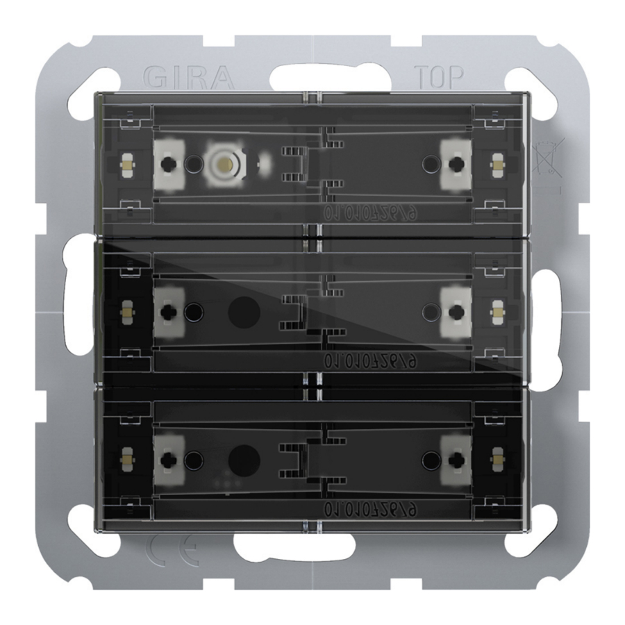
Device components
Front view
Figure 1: Device components 3-gang ("standard installation position", horizontal rockers)

Figure 2: Device components 3-gang (installation position "turned by -90°", vertical rockers)

- Operating rockers (accessory)
- Status LED
1...6 Buttons assignment and status LED
Rear view

Figure 3: Device components - rear side
- Device connection terminal for remote sensor
- Bus connection
- Retaining clips for device fixation at the supporting frame
- Supporting frame
System information
This device is a product for the Gira One Smart Home system. The Gira One system is commissioned easily and in a time-saving manner using the Gira Project Assistant. The Gira One Smart Home system enables the control and automation of lighting, heating and shading, as well as connection to various third-party systems and much more. It can be operated via Gira One switches, by app from home or securely from a remote location. Electrically skilled persons can maintain the Gira One project remotely free of charge.
Data transmission between the Gira One devices is encrypted. This provides protection against third-party access and manipulation.
Commissioning is carried out with the free Gira Project Assistant (GPA), version 5 or higher. Free function and security updates are also transferred to the Gira One devices with the GPA.
The Gira One system is based on the globally proven KNX smart home standard.
Intended use
- Operation in Gira One system
- Operation of loads, e.g. lights, shading
- Mounting in appliance box with dimensions according to DIN 49073
Product characteristics
- Push-button sensor 4 comfort for system 55 for the operation of Gira One loads
- Integrated temperature sensor for measuring the room temperature
- Integrated air humidity sensor for measuring the ambient air humidity
- Input for external remote sensor for measuring the floor temperature
- Programming and commissioning with the Gira Project Assistant (GPA), version 5.1 or higher
- Encrypted data transmission between the Gira One devices
- Push-button sensor 4 comfort combinable in Gira system 55
Operating functions
- Switching loads, such as light, socket or pump
- Dim the light
- Operation of shading and ventilation loads (Venetian blinds, shutters, roof windows, roof domes and awnings)
- Convenient group control of switching, dimming, shading and ventilation loads
- Recalling scene variants
- Operation as staircase switch for activation of staircase function with switching and dimming loads
- Function as floor call push-button together with the Gira G1
- Control of Sonos audio devices
- Control of hue loads
- Control of eNet loads
- Function as door or garage door opener
- Boost function
Room temperature
- Temperature calibration for the integrated temperature sensor
LED indication
- The brightness of the status LED can be set to 5 levels and OFF
- The colour of the status LEDs (red, green, blue, yellow, cyan, orange, violet or white) can be set
- Function selection of the status LEDs can be set according to the rocker function: always OFF, always ON, actuation display or status display
Operation
- Switch: Short press on button.
- Dim: Long press on button. The dimming process ends when the button is released.
- Move Venetian blind: Long press on button.
- Stop or adjust Venetian blind: Short press on button.
Information for electrically skilled persons
Mounting and electrical connection

Electric shock when live parts are touched.
Electric shocks can be fatal.
Cover up live parts in the installation environment.
The push-button sensor (see figure 4) can be installed horizontally ("standard installation position") or vertically ("turned by -90°" installation position).

Figure 4: Push-button sensor
 For horizontal installation ("standard installation position") the top of the pushbutton sensor is labelled with TOP.
For vertical installation ("turned by -90°" installation position) the left side of the push-button sensor is labelled with TOP.
- Retaining clips for device fixation at the supporting frame
- Programming button
- Programming LED
- Temperature sensor
Mounting and connecting the device

Figure 5: Mount device
- Operating rockers (accessory)
- Retaining clips for device fixation at the supporting frame
- Supporting frame
- Cover frame (accessory)
- Push-button sensor
- Box screws
The device should be used in an air-tight appliance box. Otherwise temperature and humidity reading can be negatively influenced by draughts.
- Enter or scan the device certificate and add it to the project. A high resolution camera should be used to scan the QR code.
- The device certificate should be removed from the device during mounting.
- Document all passwords and keep them safe.
Precondition: The installation position of the push-button sensor is defined.
- Mount supporting frame in the right orientation, "standard installation position" or "turned by -90°", on an appliance box.
![information]() Note the TOP marking.
Note the TOP marking.
![information]() Use the supplied box screws.
Use the supplied box screws. - Pull off commissioning rockers from push-button sensor.
![information]() The push-button sensor is delivered with commissioning rockers. The operating rockers suitable for the push-button sensor must be ordered separately (see accessories).
The push-button sensor is delivered with commissioning rockers. The operating rockers suitable for the push-button sensor must be ordered separately (see accessories). - Connect bus line with device connection terminal observing the correct polarity (red = +, black = -).
- Optional: Connect remote sensor (see accessories) to connection for remote sensor. The relevant device connection terminal is included with the remote sensor.
- Fit the cover frame flushly. The cover frame is fixed via the push-button sensor.
- Attach the push-button sensor with cover frame onto the supporting frame. Push-button sensor can be put into operation.
![information]() Make sure the that the retaining clips properly fit in the supporting frame.
Make sure the that the retaining clips properly fit in the supporting frame.
Commissioning
Commissioning the device
The device is commissioned with the Gira Project Assistant (GPA), version 5.1 or higher.
All status LEDs are switched off during programming. As soon as the programming is successfully completed, the status LEDs carry out their parameterised function.
When the program is discharged and the bus voltage is connected, all status LEDs initially light up white. Whenever a button is actuated, the respective illuminated status LED changes colour (white → red → green → blue → yellow → cyan → orange → violet → white →...).
Safe-state mode
The safe-state mode stops the execution of the loaded program.
Only the system software of the device is still functional. Diagnosis functions and programming of the device are possible.
Activating safe-state mode
- Switch off the voltage.
- Press and hold down the programming button.
- Switch on voltage.
The safe-state mode is activated. The programming LED flashes slowly (approx. 1 Hz).
Release the programming button only after the programming LED starts flashing.
Deactivating safe-state mode
- Switch off the voltage or carry out programming.
Master reset
The master reset restores the basic device settings (firmware remains in place). The device must then be recommissioned with the GPA.
Performing a master reset
Precondition: The safe-state mode is activated.
- Press and hold down the programming button for > 5 seconds until the programming LED starts flashing quickly.
- Release the programming button.
The device performs a master reset. The programming LED is switched on.
The device restarts and is in delivery state.
Mounting the rockers
- Slide the side of the rocker into place (see figure 6).

Figure 6: Slide the side of the rocker into place - Press in the middle of the rocker (see figure 7).

Figure 7: Press lightly in the middle of the rocker
The rocker snaps into place.
Device is ready for operation.


In order to optimise the gap dimensions between the rockers and the cover frame, the rockers can be moved slightly after snapping into place.
Dismantling
- Carefully pull the push-button sensor forward together with the cover frame.
- Pull the rockers on one side to loosen them from the push-button sensor.
![]()
Figure 8: Dismantle the push-button sensor

Exchanging labelling field
The rocker has a labelling field
- Search for a notch in the cover of the labelling field by feeling with a finger (see figure 9).
![]()
Figure 9: Feel for a notch in the labelling field cover
- Pull on one side at the notch in the cover of the labelling field to separate from the rocker (see figure 10). The labelling field is uncovered.
![]()
Figure 10: Remove the labelling field cover
- Exchange the labelling field.
- Press the cover of the labelling field onto the rocker so that it snaps into place.
The labelling field is exchanged.


Technical data
Rated voltage: DC 21... 32 V SELV
Current consumption, bus: 8... 18 mA
Connection type for bus: Device connection terminal
Connecting cable, bus: EIB-Y (St)Y 2x2x0.8
Protection class: III
Installation dimensions (see figure 11)

Figure 11: Installation dimensions
Construction height:
A = 11.9 mm
A = 12.5 mm (stainless steel rocker set)
Installation depth: B = 13.8 mm
Connection cable remote sensor (see accessories)
Cable type extension:
NYM-J 3×1.5 or J-Y(St)Y 2×2×0.8
Total length remote sensor line: Max. 30 m
Ambient conditions
Ambient temperature: -5... +45°C
Storage/transport temperature: -20... +70°C
Parameter list
Parameters that can be set via the GPA:
| Status LED brightness |
|
| The brightness of the status LEDs can be defined here. In the case of the push-button sensor 2-gang or 3-gang, this setting applies to all LEDs. | |
| Colour | Red, green, blue, yellow, cyan, orange, violet, white |
| The colour of the status LEDs can be defined here. In the case of the push-button sensor 2-gang or 3-gang, the colour of the status LEDs can be defined separately for each rocker. | |
| Function |
|
| The function of the status LEDs can be defined here. In the case of the push-button sensor 2-gang or 3-gang, the function of the status LEDs can be defined separately for each rocker. The settings have the following functions:
| |
| Temperature calibration | - 12.8... 12.7 K |
| The value for the temperature calibration can be entered here if the temperature measured by the temperature sensor in the push-button sensor or by the connected remote sensor differs from the actual room temperature. | |
| Temperature calibration | - 12.8... 12.7 K |
| To determine the temperature deviation, the actual room temperature should be detected with a reference measurement using a calibrated temperature measuring device. The measured value must be raised if the value measured by the sensor is below the actual temperature. The measured value must be lowered if the value measured by the sensor is above the actual temperature. | |
Accessories
Individually labelled rocker sets are available from the Gira inscription service www.beschriftung.gira.de.
| Rocker set, 1-gang for pushbutton sensor 4 | Order no. 5751.. |
| Rocker set, 1-gang, inscribable, for pushbutton sensor 4 | Order no. 5761.. |
| Rocker set, 1-gang, inscribable, for pushbutton sensor 4 | Order no. 5771.. |
| Rocker set, 2-gang for pushbutton sensor 4 | Order no. 5752.. |
| Rocker set, 2-gang, inscribable, for pushbutton sensor 4 | Order no. 5762.. |
| Rocker set, 2-gang, inscribable, for pushbutton sensor 4 | Order no. 5772.. |
| Rocker set, 4-gang for pushbutton sensor 4 | Order no. 5753.. |
| Rocker set, 4-gang, inscribable, for pushbutton sensor 4 | Order no. 5763.. |
| Rocker set, 4-gang, inscribable, for pushbutton sensor 4 | Order no. 5773.. |
| Remote sensor | Order no. 1493 00 |
Safety instructions
![]()
Electrical devices may be mounted and connected only by electrically skilled persons.
Serious injuries, fire or property damage are possible. Please read and follow the manual fully.
Danger of electric shock. During installation and cable routing, comply with the regulations and standards which apply for SELV circuits.
This manual is an integral part of the product, and must remain with the customer.
Tel +49(0)21 95 - 602-0
Fax +49(0)21 95 - 602-191
info@gira.de
Documents / Resources
References
![www.beschriftung.gira.de]() Gira Inscription Service
Gira Inscription Service![b.gira.de]() Suche
Suche![b.gira.de]() Suche
Suche![b.gira.de]() Suche
Suche![b.gira.de]() Suche
Suche![b.gira.de]() Suche
Suche![b.gira.de]() Suche
Suche![b.gira.de]() Suche
Suche![b.gira.de]() Suche
Suche![b.gira.de]() Suche
Suche![b.gira.de]() Gira Fernfühler
Gira Fernfühler![www.gira.de]() Schalter, Steckdosen & smarte Technik | Gira
Schalter, Steckdosen & smarte Technik | Gira

Download manual
Here you can download full pdf version of manual, it may contain additional safety instructions, warranty information, FCC rules, etc.
Advertisement


Need help?
Do you have a question about the One and is the answer not in the manual?
Questions and answers