Table of Contents
Advertisement
Quick Links
Pushbutton sensor 4 Standard / Komfort System 55
Pushbutton sensor 4 Standard, 1-gang System 55
Order no.: 5011 00
Pushbutton sensor 4 Standard, 2-gang System 55
Order no.: 5012 00
Pushbutton sensor 4 Standard, 3-gang System 55
Order no.: 5013 00
Pushbutton sensor 4 Komfort, 1-gang System 55
Order no.: 5041 00
Pushbutton sensor 4 Komfort, 2-gang System 55
Order no.: 5042 00
Pushbutton sensor 4 Komfort, 3-gang System 55
Order no.: 5043 00
Operating instructions
1
Safety instructions
Electrical devices may only be mounted and connected by electrically skilled persons.
Serious injuries, fire or property damage possible. Please read and follow manual fully.
Danger of electric shock. During installation and cable routing, comply with the regulations and
standards which apply for SELV circuits.
This manual is an integral part of the product, and must remain with the end customer.
32406202
10868646
29.06.2022
1 / 16
Advertisement
Table of Contents

Subscribe to Our Youtube Channel
Related Manuals for Gira System 55 Pushbutton sensor 4 Standard


Summary of Contents for Gira System 55 Pushbutton sensor 4 Standard
- Page 1 Pushbutton sensor 4 Standard / Komfort System 55 Pushbutton sensor 4 Standard, 1-gang System 55 Order no.: 5011 00 Pushbutton sensor 4 Standard, 2-gang System 55 Order no.: 5012 00 Pushbutton sensor 4 Standard, 3-gang System 55 Order no.: 5013 00 Pushbutton sensor 4 Komfort, 1-gang System 55 Order no.: 5041 00 Pushbutton sensor 4 Komfort, 2-gang System 55...
-
Page 2: Device Components
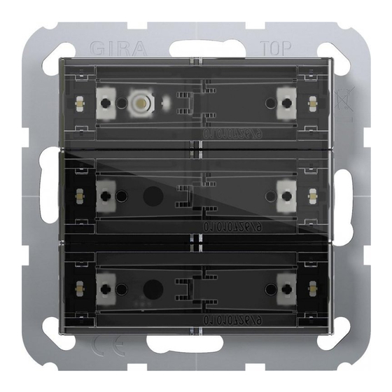
Pushbutton sensor 4 Standard / Komfort System 55 Device components Front view Figure 1: Device components 3-gang ("standard installation location", horizontal rockers) Figure 2: Device components 3-gang (installation location "turned by -90°", vertical rockers) Operating rockers (accessory) Status LED 1...6 Push-buttons assignment and status LED 32406202 10868646 29.06.2022... - Page 3 Pushbutton sensor 4 Standard / Komfort System 55 Rear view Figure 3: Device components - rear side Device connection terminal for remote sensor (only for "comfort" device variant) Device connection terminal KNX Retaining clips for device fixation at the supporting frame Supporting frame 32406202 10868646...
-
Page 4: System Information
The device can be updated. Firmware can be easily updated with the Gira ETS Service App (additional software). The device is KNX Data Secure capable. KNX Data Secure offers protection against manipula- tion in building automation and can be configured in the ETS project. -
Page 5: Product Characteristics
Pushbutton sensor 4 Standard / Komfort System 55 Product characteristics Product characteristic per product variant Comfort Standard Push-button sensor functions switching, dimming and > > colour temperature control, colour control and bright- ness, Venetian blind, value transmitter, scene exten- sion, 2-channel operation and controller extension ad- justable Controller extension with operating mode selection, >... -
Page 6: Operation
Pushbutton sensor 4 Standard / Komfort System 55 Operation Depending on the programming, a rocker can have up to two functions assigned to it. Operation is carried out by short or long pressing the buttons and depends on the specific function. 6.1 Examples for operating various standard applications ■... - Page 7 Pushbutton sensor 4 Standard / Komfort System 55 Information for electrically skilled persons 7.1 Mounting and electrical connection DANGER! Mortal danger of electric shock. Cover up live parts in the installation environment. The push-button sensor (Figure 4) can be installed horizontally ("standard installation location") or vertically ("turned by -90°"...
- Page 8 Pushbutton sensor 4 Standard / Komfort System 55 Mounting and connecting the device Figure 5: Mounting the device Operating rockers (accessory) Retaining clips for device fixation at the supporting frame Supporting frame Cover frame (accessory) Push-button sensor Box screws The device should be used in an air-tight appliance box. Otherwise temperature and hu- midity reading can be negatively influenced by draughts.
- Page 9 Pushbutton sensor 4 Standard / Komfort System 55 The physical address is programmed (see chapter Commissioning } Page 10) in the next work step. The rockers can then be mounted (see chapter Mounting the rock- ers } Page 12). 32406202 10868646 29.06.2022 9 / 16...
- Page 10 Pushbutton sensor 4 Standard / Komfort System 55 7.2 Commissioning Programming the physical address and application program Project design and commissioning with ETS from version 5.7.5 and above. The programming button is located under the first rocker. Precondition: The device is connected and ready for operation. The first rocker is dismantled.
-
Page 11: Master Reset
Pushbutton sensor 4 Standard / Komfort System 55 7.2.1 Safe-state mode The safe-state mode stops the execution of the loaded application program. If the device does not work properly - for instance as a result of errors in the project design or during commissioning - the execution of the loaded application program can be halted by activ- ating the safe-state mode. - Page 12 Pushbutton sensor 4 Standard / Komfort System 55 7.3 Mounting the rockers ■ Slide the side of the rocker into place (Figure 6). Figure 6: Slide one side of the rocker into place ■ Press in the middle of the rocker (Figure 7). Figure 7: Press lightly in the middle of the rocker The rocker snaps into place.
- Page 13 Pushbutton sensor 4 Standard / Komfort System 55 7.4 Dismantling ■ Carefully pull the push-button sensor forward together with the cover frame. ■ Pull the rockers on one side to loosen them from the push-button sensor. Figure 8: Dismantle the push-button sensor 32406202 10868646 29.06.2022...
- Page 14 Pushbutton sensor 4 Standard / Komfort System 55 7.5 Exchanging labelling field The rocker has a labelling field ■ Search for a notch in the cover of the labelling field by feeling with a finger (Figure 9). ■ Pull on one side at the notch in the cover of the labelling field to separate from the rocker (Figure 10).
-
Page 15: Technical Data
Pushbutton sensor 4 Standard / Komfort System 55 Technical data KNX medium TP256 Commissioning mode S-mode Rated voltage DC 21 ... 32 V SELV Current consumption KNX 8 ... 18 mA Connection mode KNX Standard device connection terminal Connecting cable KNX EIB-Y (St)Y 2x2x0.8 Protection class Installation dimensions (Figure 11) -
Page 16: Warranty
Pushbutton sensor 4 Standard / Komfort System 55 Accessories Individually labelled rocker sets are available from the Gira inscription service www.bes- chriftung.gira.de. Rocker set, 1-gang for pushbutton sensor 4 Order no. 5751 .. Rocker set, 1-gang, inscribable, for pushbutton sensor 4 Order no.
Need help?
Do you have a question about the System 55 Pushbutton sensor 4 Standard and is the answer not in the manual?
Questions and answers