PLUSOPTIX A12C User Manual
Mobile pediatric autorefractor
Hide thumbs
Also See for A12C:
- Short manual (11 pages) ,
- Software upgrade (2 pages) ,
- Short manual (9 pages)

Related Manuals for PLUSOPTIX A12C


Summary of Contents for PLUSOPTIX A12C
- Page 1 Mobile Pediatric Autorefractor “plusoptiX A12C” “plusoptiX A12R” User Manual Release: 2015-10-16 Plusoptix GmbH Neumeyerstrasse 48 90411 Nuremberg Germany www.plusoptix.eu Page 1/68 Englisch...
-
Page 2: Table Of Contents
Activate WLAN (only plusoptiX A12C) ..............29 4.1.5 Connect to EMR (only plusoptiX A12C) ..............33 4.1.5.1 Transferring data in CSV format (only plusoptiX A12C) ..........33 4.1.5.2 Transferring data in GDT format (only plusoptiX A12C) ..........35 4.1.6 Export data (only plusoptiX A12C) ................37 4.1.7... - Page 3 Table of figures Figure 1: Device in cardboard box (plusoptiX A12C) ............. 6 Figure 2: Front view of the device (plusoptiX A12C) .............. 7 Figure 3: Rear view of the device (plusoptiX A12C) ............... 8 Figure 4: Battery compartment view of the device (plusoptiX A12C)........9 Figure 5: Switching between a screen and the help text ............11...
-
Page 4: Use According To Purpose And Responsibility Of The Operator
The symbols used have the following meanings: Read this user manual. Warning notes are designated using this warning symbol. Mobile Pediatric Autorefractor "plusoptiX A12C" and "plusoptiX A12R" comply with 0123 the specifications of Guideline 2007/47/EG for medical devices. - Page 5 - The operator is responsible for ensuring that in the case of servicing or a warranty claim, Mobile Pediatric Autorefractor "plusoptiX A12C", "plusoptiX A12R" respectively, is only opened by Plusoptix or an authorized Plusoptix distributor. Opening the device exposes you to a risk of an invisible electric shock. In addition, the device warranty becomes null and void, as does the approval as a medical device.
-
Page 6: Commissioning The Device
- User Manual for plusoptiX A12 - Mobile Pediatric Autorefractor "plusoptiX A12C" or "plusoptiX A12R" - Medical power adapter MES30B-3P1J - 110V/230V power cord (in compartment under the "plusoptiX A12C" or "plusoptiX A12R") - 6 x rechargeable AA batteries - SD card (inserted into device) Optional accessories: - +3,00dpt. -
Page 7: Learning About The Device
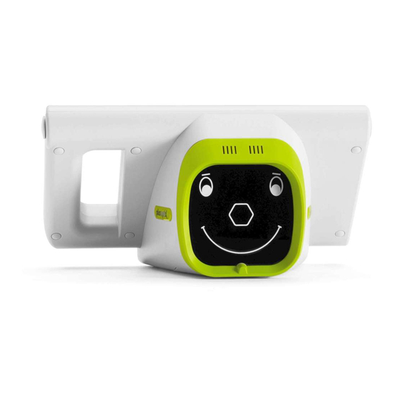
Figure 2: Front view of the device (plusoptiX A12C) The camera lens and the LEDs required for illuminating the images are located behind the black protective shield with the stylized face. This face is also used as a fixation aid. -
Page 8: Figure 3: Rear View Of The Device (Plusoptix A12C)
A12C has a 5.7 inch screen with capacitive touch sensor located on the rear side of the device. To activate one of the functions displayed on the screen, all you need to do is gently touch the screen. -
Page 9: Inserting And Charging The Rechargeable Batteries
Battery compartment Type plate Figure 4: Battery compartment view of the device (plusoptiX A12C) Attention: If you need to put the device on its rear side, e.g. to insert or replace the rechargeable batteries, please place a soft cloth under the device. -
Page 10: Switching The Device On And Off
After inserting the rechargeable batteries, close the battery compartment cover and place the device in front of you. Now connect the medical power adapter with its power cable to the wall socket and check whether voltage is present (green light diode at the top of the medical power adapter lights up). -
Page 11: Screen Displays And Help Texts
The WLAN information (1) is only displayed if the WLAN is activated in the Settings. This function is only available for the plusoptiX A12C. The battery status symbol (2) flashes when the 12V charging cable is connected and the rechargeable batteries are charged. -
Page 12: Performing Measurements
3 Performing Measurements Mobile Pediatric Autorefractors "plusoptiX A12C", "plusoptiX A12R" respectively, measures both eyes simultaneously (binocular) in 0.5 seconds at a distance of one meter (3.3 feet). Therefore even small children with a short attention span can be measured starting at the age six months. -
Page 13: Preparing For A Measurement
You can start a anonymous measurement by pressing the Shutter (see chapter 3.4 "Starting a measurement and positioning the camera"). The plusoptiX A12C possesses a patient database. To enter new patient data (see chapter 3.3 "Entering patient data"), or to call up patient data that has already been saved (see chapter 4.1.8 "Retrieve patients from database"), touch button (3) to move to patient data entry. -
Page 14: Entering Patient Data (Only Plusoptix A12C)
Entering patient data (only plusoptiX A12C) To be able to uniquely identify a patient in the database, you need to enter either date of birth, first name and last name, or an ID number. As an option, examination location and/or contact information can also be saved in the database (shown with a dotted line in the figure below). -
Page 15: Screenshot 3: Entering The Date Of Birth
You can enter the date of birth in any form you wish. Touch button (1) to enter the year of birth, button (2) to enter the month of birth and button (3) to enter the day of birth. Screenshot 3: Entering the date of birth After entering the date of birth, you will see a green checkmark (4) as confirmation on the tab. -
Page 16: Screenshot 4: Entering A First Name
Use the screen keypad to enter the patient data. Touch: - the Caps Lock key (1) to switch back and forth between lower- and upper case typing - the SYM key (2) to insert special characters - the Backspace key (3) to delete the last character. Please read chapter 4.1.14 "External mouse or keyboard"... -
Page 17: Starting A Measurement And Positioning The Camera
Starting a measurement and positioning the camera Hold the device as you would hold a tablet PC and press the Shutter with your right thumb. Figure 8: Holding the camera and operating the shutter Place the device approximately 1.2 meters (4 feet) away from the child at eye level. Although the measurement distance is one meter (3.3 feet), a degree of practice is required to estimate this distance. -
Page 18: Figure 10: Recognizing Correct Measurement Distance
Align camera so that both eyes can be seen on the screen. Then slowly move towards patient until camera picture on screen is in clear focus. In the beginning the pupils are framed with white boxes (i.e. the picture is blurred), then by red circles and finally by green circles. Stop moving once a green line is plotted in between both pupils and a second “warble”... - Page 19 If you do not obtain measurement results, check whether the following measurement prerequisites are met: a) Measurement distance is correct: Measurement distance must be in between 95 cm (3.1 feet) and 105 cm (3.9 feet). Check whether the camera image on screen is in focus. You should be able to see individual hairs of eyelashes and eyebrows on screen.
-
Page 20: Checking And Documenting Measurement Results
If a anonymous measurement was performed, the measuring report can be saved manually by touching the printer button (3). After touching the printer button (3) the patient data entry screen is displayed by plusoptiX A12C (see chapter 3.3 “Entering patient data (only plusoptiX A12C)”). PlusoptiX A12R displays a input field instead. - Page 21 In this case Measurement report is saved anonymously. If a SD card was inserted and patient data was entered before the measurement with plusoptiX A12C, a measurement report will automatically be saved on the SD card (see chapter 4.1.9 “Save and print a measurement report”).
-
Page 22: Screenshot 5: Check Measurement Result
Measurement results are displayed separately for right eye (OD) and left eye (OS). Gaze chart OS Gaze chart OD Status line Screenshot 5: Check measurement result Spheres (SPH) Cylinder (CYL) in diopters in diopters Pupil diameter Axis (A) (Ø) in degrees in millimeters Asymmetry (ASY) Pupil distance... -
Page 23: Screenshot 6: Review Video Screen
Review video screen Touch Play button (1) in navigation bar to play back the entire measurement video in slow motion. During playback Play button (1) is replaced by Pause button (2). Touch Pause button (2) to interrupt playback and inspect a single picture closely. The inspection of images is primarily used for detecting media opacities that do not cause a measurement to abort. -
Page 24: Screenshot 7: Review Database Entries Screen
Review database entries screen ( only plusoptiX A12C) Every measurement is documented in the database in chronological order, automatically. This listing shows at a glance how a patient's measurements have changed over time. Yellow entries indicate aborted measurements and green or red entries show successful measurements. -
Page 25: Perform Next Measurement
- If new patient data are to be entered or called up from the database before the next measurement (plusoptiX A12C only), in both cases (i.e. after a cancelled or a successful measurement) this can be done by pressing the button (3). -
Page 26: Practical Tips
- Set date & time (4) – see chapter 2.4 - Choose language (5) – see help text - Set-up screen lock (6) – see chapter 4.1.3 (only plusoptiX A12C) - Configure software (7) – see chapter 4.1.13 - Activate WLAN (8) – see chapter 4.1.4 (only plusoptiX A12C) - Connect to EMR (9) –... -
Page 27: Customize Basic Settings
Only plusoptiX A12C: Use of a comma or semicolon as a separator in CSV files The chosen separator is used for all CSV files that the device saves. Only CSV files that use the chosen separator can be imported. -
Page 28: Set-Up Screen Lock (Only Plusoptix A12C)
4.1.3 Set-up screen lock (only plusoptiX A12C) The screen can be locked to prevent unauthorized access to patient data saved in the device. To be able to lock the screen, screen lock must first be activated in Settings, and a six-digit PIN must be entered. -
Page 29: Activate Wlan (Only Plusoptix A12C)
4.1.4 Activate WLAN (only plusoptiX A12C) The device is equipped with a WLAN interface. This WLAN interface is used to connect to either a DHCP server. To save battery power WLAN interface is deactivated at delivery. Note: Switch on DHCP server before activating WLAN interface. -
Page 30: Screenshot 13: List Of Active Wlan Connections
The device then automatically searches for all available networks within range and displays these after approximately one minute. If there are displayed more than three available networks, you can scroll through the list by touching the Down arrow (1). Touching the Repeat button (2) will start the search for wireless networks again. -
Page 31: Screenshot 14: Wlan Network Without Password
DHCP server, touch the appropriate entry on the screen. Confirm your selection with the green tick (2) in the Navigation Bar. After a short time the screen is closed automatically and the Settings screen appears. The plusoptiX A12C is now connected with your wireless DHCP server. -
Page 32: Screenshot 16: Active Wlan Connection
If the device is already connected to a WLAN, a green Checkmark (1) is displayed instead of a Warning symbol. The name of the WLAN is marked in orange, and the IP address is displayed next to the password (2). WLAN active IP address Screenshot 16: Active WLAN connection... -
Page 33: Connect To Emr (Only Plusoptix A12C)
Note: To ensure that data exchange works, your EMR system has to support this interface. Check with your EMR system provider if this Plusoptix device is compatible. Please read chapter 4.1.4 “Activate WLAN” to connect the device to your wireless DHCP server, first. - Page 34 Data fields in a CSV file have to: - be separated using the separator "," or ";" as selected in Basic settings - contain five separators (the separator after "contact" is an optional addition) - adhere to this sequence: last name, first name, date of birth, patient ID, location, contact - include either last name, first name and date of birth or patient ID, location and contact information are always optional - use same date format as set in Date &...
-
Page 35: Transferring Data In Gdt Format (Only Plusoptix A12C)
4.1.5.2 Transferring data in GDT format (only plusoptiX A12C) Touch GDT button (1) to choose GDT file format. Screenshot 19: GDT settings for EMR integration Text files are saved in a so-called transfer directory (URL:\\plusoptix12\transfer\) for data exchange. The names of these text files are comprised of sender and recipient identifiers. -
Page 36: Screenshot 20: Start Screen With An Active Connection To Emr
If the device receives patient data from the EMR system in the transfer directory, this data is displayed in Header on start screen (1) and under "Repeat Measurement" (2). Screenshot 20: Start screen with an active connection to EMR Note: Note that it is now impossible either to enter patient data manually or to retrieve patient data from the database. -
Page 37: Export Data (Only Plusoptix A12C)
4.1.6 Export data (only plusoptiX A12C) All patient data and measurement results are stored in the database. This database can be used to create backup copies and reports. Note: To save storage space, video files are not stored in the database. The last image for each measurement is stored together with the measurement report (see chapter 4.1.9 "Save and print a measurement report") on the SD card. -
Page 38: Screenshot 22: Generate A Report
Note: If you restore a database, a backup copy of the existing database is first saved to the USB storage device. The existing database is then overwritten with the database to be restored. The two databases (backup copy on the USB device and the existing database in the device) are not merged. -
Page 39: Import Patient Data (Only Plusoptix A12C)
4.1.7 Import patient data (only plusoptiX A12C) Patient data (i.e. a roster of patients) can be imported from a CSV table via the USB port. Data fields in a CSV table to be imported have to: - be separated using the separator "," or ";" as selected in Basic settings - contain five separators (the separator after "contact"... -
Page 40: Retrieve Patients From Database (Only Plusoptix A12C)
4.1.8 Retrieve patients from database (only plusoptiX A12C) If you have already entered or imported patient data, you can retrieve a patient's data record from the database. To do so, proceed exactly as if you were entering data for a new patient. -
Page 41: Save And Print A Measurement Report
(1) in the navigation bar. After touching the printer button (1) the patient data entry template is displayed by plusoptiX A12C (see chapter 3.3 “Entering patient data (only plusoptiX A12C)”). PlusoptiX A12R displays a input field instead. -
Page 42: Compatible Printers And Network Printing
P12 The plusoptiX P12 is battery-powered and has an infrared interface. Hold the device pointed towards the infrared receiver of the plusoptiX P12 at a distance of approximately 1 m. Note: Sending print orders to the plusoptiX P12 over the infrared interface only works... -
Page 43: Figure 15: Self-Adhesive Label Sample
PDF-file of the measuring report from your workplace computer. For this there are three different possible methods of access available: Connection via your DHCP WLAN server – see chapter 4.1.4 (only plusoptiX A12C) File access with URL: \\plusoptix12\pdf (Windows Explorer), smb://plusoptix12/pdf (Apple Finder) Connection via Mini-USB-cable –... -
Page 44: Sd Card And Usb Interfaces
4.1.11 SD card and USB interfaces You can connect two storage media devices (one SD card and one USB storage device) to the plusoptiX device. Note: All interfaces are installed upside down. Therefore all connectors must also be turned around before being inserted (i.e. USB symbol faces downwards). -
Page 45: Mini-Usb Interface
To avoid damage to the device, do not connect any other external device to the Mini- USB port except your workplace computer. The device features a 5-pole-Mini-B-USB port. This is used by Plusoptix as part of the production process and in the case of a service and warranty issue. The connection over a Mini-USB cable is available for all A12x devices from the supplement “01F”... -
Page 46: Screenshot 23 : Downloading Software Update
To download a software update to your device: Touch the button to configure the software (2) in the Settings (1) Touch the symbol (3) to download the current software Confirm with the green tick (4). You will be guided through the download with the help of status messages on the screen. -
Page 47: Figure 16: Software Update Via Wlan
Downloading Software Update via WLAN (nur plusoptiX A12C) With active WLAN-connection you will be guided through the update with the help of the following status messages (see Figure 16). Note: Depending on the signal strength of the WLAN- and the Internet connection, a software update over WLAN can take about 30-40 min. -
Page 48: Figure 17 : Software Update Via Mini-Usb-Cable
Action recommendations on your workplace computer Please open Windows Explorer or Apple Finder choose corresponding file folder. File access with URL: Removable medium\pdf Start Plusoptix Image Downloader to download the Software Update. Parallel processes Figure 17 : Software Update via Mini-USB-cable Page 48/68... -
Page 49: External Mouse Or Keyboard
4.1.14 External mouse or keyboard To simplify data entry, you can use an input stylus (i.e. touch pen). Alternatively, you can connect a USB mouse or USB keyboard. Connect your input device to the USB port. You can also connect wireless input devices as an alternative to cable-based input devices. Note: All device ports are located upside down, that is, the plugs must also be turned around before being inserted (i.e. -
Page 50: Trouble-Shooting Guide
Trouble-shooting guide Vast majority of service queries relate to malfunctions when switching device on, malfunctions when using touch screen or error messages when performing a measurement. It is only in rare cases that these malfunctions are caused by broken hardware. The following chapters provide a step-by-step guide for trouble-shooting. - Page 51 Note: Bear in mind that grayed out buttons on screen are deliberately inactive. plusoptiX A12C: Place the fingertip of your index finger flat on the screen to select a button. Do not tap on the screen with the fingertip or finger nail.
-
Page 52: Error Messages When Performing A Measurement
4.2.3 Error messages when performing a measurement If no measurement results are available, an error message and an action recommendation followed by a "Measurement aborted" status message are displayed. Error message Action recommendation Status line Screenshot 24: Measurement result page after a "Measurement cancellation"... - Page 53 a) Picture out of focus In this example the patient is too far away; besides the eyes, half the patient’s face can be seen in the camera image. In this example the patient is too close to the camera; both eyes are close to the left and right edges of the camera image.
- Page 54 b) Patient does not focus on camera! In this example the patient is looking to the left of the camera (from the patient’s perspective). The red dots in the gaze chart illustrate this line of vision. Cause: This error message is displayed if the patient is not looking at the hexagonal nose in the camera face.
- Page 55 Pupils too big! In this example the pupils are larger than 8.0 mm. Cause: This error message is displayed if one or both of the pupil diameters is larger than 8.0 mm. Reason: In the case of large pupils, the pupillary reflex may be overexposed, which results in cancellation of the measurement without result.
- Page 56 e) Pupils not found! In this example both pupils are not completely visible on the camera image. In this example the patient is wearing glasses and the pupils are partially covered due to infrared light reflections on the frame of the glasses and on the lenses. Note: The error message "No pupils found!"...
- Page 57 Too much IR ambient light! In this example the sun is shining onto the patient’s face from the left side. This is apparent from the shadow caused by the nose. Cause: This error message is displayed if too much infrared light is present in the examination room.
- Page 58 In this example the patient has tilted her head slightly down and is looking up into the camera. The pupils are partially covered by the upper eyelids. In this example the right pupil is covered by the upper eyelashes and the left pupil by hair.
- Page 59 h) Corneal reflexes are too dark! In this example too little infrared light is reflected from the retina. Cause: This error message is displayed if the pupillary reflexes are too dark. Reason: The measurement takes place with infrared light, which is reflected from the cornea.
-
Page 60: Maintenance, Calibration, Servicing And Warranty
The device comes with a 12-month ship-in warranty from the date of purchase. A warranty extension is available. Please contact Plusoptix or your authorized Plusoptix dealer if you want to purchase a warranty extension. The warranty becomes null and void in the case of external damage, improper use, incorrect cleaning, or transportation without device cardboard box. -
Page 61: Technical Specifications
Screen Size 4,3‘‘, Ratio 5:3 (800 x 480 Pixel) Monitor plusoptiX A12R Resistive touch sensor Standard EN 60601-1 WLAN interfaces standards (only plusoptiX A12C): Physical layer Supports 802.11 b and g standards Network architecture types Communication to wired networks via Access Points... -
Page 62: Ambient Conditions For Operation And Storage
Max. height <2.000m (78740’’) Max. height for operation Size and weight with and without cardboard box 260 x 140 x 140 mm (10¼ x 5½ x 5½’’) plusoptiX A12C Size without cardboard box Weight 1,0 kg (35,27 oz) plusoptiX A12C Size 240 x 430 x 270 mm (9¾... - Page 63 Emissions Test Compliance Electromagnetic environment - Guidance RF emissions are very low and are not likely to RF Emission CISPR 11 Group 1 cause any interference in nearby electronic equipment. The device is suitable for use in all RF Emission CISPR 11 Class B establishments, including domestic establishments Harmonic Emissions IEC...
-
Page 64: Plusoptix P12 (Optional Label Printer)
7 plusoptiX P12 (optional label printer) Description The plusoptiX P12 is a wireless, battery-operated printer with infrared interface. It is not included in the scope of delivery and has to be ordered separately. Attention: The printer drivers are pre-installed on all A12x devices from the supplement “01D”... -
Page 65: Figure 19: Bottom Of Plusoptix P12
For charging the rechargeable batteries, exclusively use the power supply MES30B-3P1J supplied with your plusoptiX A12x. To charge the batteries use the medical power supply unit MES30B-3P1J. This is the same power supply unit that is also used to charge the batteries of the plusoptiX A12x. Page 65/68... -
Page 66: Figure 20: Open Cover And Insert Paper
The cover engages audibly. Note: Use only original paper available from Plusoptix or a Plusoptix authorised dealer. Switching printer on and off To switch on, briefly press the On button. The printer starts immediately and is ready for operation as soon as the status lamp flashes green. -
Page 67: Figure 21: Cleaning The Plusoptix P12
After each measurement with the plusoptiX A12x, any number of labels for documenting the measurement results can be printed out. To do so, align the plusoptiX A12x with the infrared receiver of the printer. The distance between plusoptiX A12x and the printer should be approximately 1 m (3,28 ft). - Page 68 Technical details Attention: For charging the rechargeable batteries, exclusively use the power supply MES30B-3P1J supplied with your plusoptiX A12x. Interface IR-receiver Temperature 0 to +50°C Storage Humidity 10 to 80% non-condensing Temperature +10 to +50°C Operation Humidity 20 to 80% non-condensing Dimensions 159.6 x 89.6 x 45.6 mm...
Need help?
Do you have a question about the A12C and is the answer not in the manual?
Questions and answers