Datalogic Matrix 120 Product Reference Manual
Image based reader
Hide thumbs
Also See for Matrix 120:
- Reference manual (144 pages) ,
- Product reference manual (188 pages)
Table of Contents
Advertisement
Quick Links
Advertisement
Table of Contents

Related Manuals for Datalogic Matrix 120


Summary of Contents for Datalogic Matrix 120
- Page 1 Matrix 120™ Image Based Reader Product Reference Guide...
- Page 2 Digimarc® and DWCODE™ are trademarks of Digimarc Corporation. All other trademarks and brands are property of their respective owners. Datalogic shall not be liable for technical or editorial errors or omissions contained herein, nor for incidental or consequential damages resulting from the use of this material.
-
Page 3: Table Of Contents
Step 1 - Connect the System ................................1 Ethernet Connections ................................1 USB Connections ..................................2 Serial Connections ..................................3 CBX100/CBX500 Pinout for Matrix 120 ......................... 4 Step 2 - Mount and Position the Reader ............................5 Step 3 - X-PRESS Configuration ..............................6 Focus/Aiming ................................... 6 Setup .................................... - Page 4 Input 2 Connections Using Matrix 120 Power ........................63 Input 2 Connections Using External Power .........................63 Outputs ......................................64 Output 1 and 2 Connections Using Matrix 120 Power ......................65 Output 1 and 2 Connections Using External Power ......................66 On-Board Ethernet Interface .................................67 User Interface - Serial Host ................................67...
- Page 5 Statistics ....................................... 148 MAINTENANCE .................................. 149 Cleaning ......................................149 TROUBLESHOOTING................................150 General Guidelines ..................................150 Windows XP SP3 and Matrix 120 USB Interface ........................150 TECHNICAL FEATURES..............................154 Electrical Features ..................................154 Optical Features ................................... 155 Environmental Features ................................155 Physical Features ..................................
-
Page 6: References
DL.CODE mini-DVD (downloaded .zip file or mini-DVD accessory) Support Through The Website Datalogic provides several services as well as technical support through its web- site. Log on to www.datalogic.com and click on the SUPPORT link which gives you access to: •... -
Page 7: Conventions
"User" refers to anyone using a Matrix 120 reader. "Reader" refers to the Matrix 120 reader. "You" refers to the System Administrator or Technical Support person using this manual to install, configure, operate, maintain or troubleshoot a Matrix 120 reader. Product Reference Guide... -
Page 8: Compliance
This evaluation was carried out in relation to the applicable points of the standards listed in the Declaration of Conformity. Datalogic products are mainly designed for integration purposes into more complex systems. For this reason it is under the responsibility of the system integrator to do a new risk assessment regarding the final installation. -
Page 9: Fcc Compliance
LED Safety LED emission according to EN 62471. Laser Safety All Matrix 120 readers contain one aiming Laser source used to position the reader. This product conforms to the applicable requirements of IEC 60825-1 and com- plies with 21 CFR 1040.10 except for deviations pursuant to Laser Notice N° 50, date June 24, 2007. - Page 10 Compliance Disconnect the power supply when opening the device during maintenance or installation to avoid exposure to hazardous laser light. The laser beam can be switched on or off through a software command. Matrix 120...
-
Page 11: Handling
Handling The Matrix 120 is designed to be used in an industrial environment and is built to withstand vibration and shock when correctly installed, however it is also a precision product and therefore before and during installation it must be han- dled correctly to avoid damage. - Page 12 • do not weld the reader into position which can cause electrostatic, heat or reading window damage. • do not spray paint near the reader which can cause reading window dam- age. Matrix 120...
-
Page 13: General View
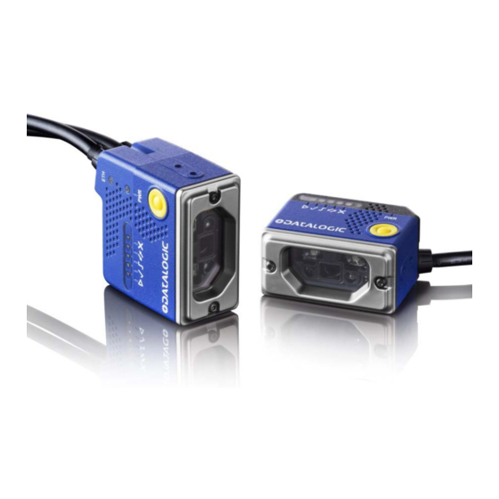
General View Matrix 120™ Serial + Ethernet Models Figure A Power - Serial Interface - I/O Cable Internal Illuminator w/Connector Ethernet Cable w/Connector Aiming System Laser Source ... - Page 14 General View Matrix 120™ Serial + USB Models Figure B Power On LED Lens HMI X-PRESS Interface Good Read LED (green) Power - Serial Interface - I/O Cable ...
-
Page 15: Rapid Configuration
-. In this layout the data is transmitted to the Host from the Matrix 120 on-board Ethernet interface by using a CAB-ETH-M0x cable. There is no need to use a crossover adapter since Matrix 120 incorporates an autocross function. Matrix 120 power and I/O device connections take place through the CBX connection box using the CAB-1011 accessory cable. -
Page 16: Usb Connections
To connect the system in a USB point-to-point configuration, you need the hardware indicated in Figure 2 -. In this layout the data is transmitted to the Host from the Matrix 120 USB interface by using a CAB-1021 accessory cable. Host CAB-1021 Matrix 120... -
Page 17: Serial Connections
-. In this layout the data is transmitted to the Host from the Matrix 120 main serial interface. Matrix 120 power and I/O device connections take place through the CBX connection box using the CAB-1011 accessory cable. When One Shot or Phase Mode Operating mode is used, the reader is activated by an External Trigger (photoelectric sensor) when the object enters its reading zone. -
Page 18: Cbx100/Cbx500 Pinout For Matrix 120
CBX100/CBX500 Pinout for Matrix 120 The table below gives the pinout of the CBX100/CBX500 terminal block connectors. Use this pinout only when the Matrix 120 reader is connected to the CBX100/CBX500 by means of the CAB-1011 accessory cable: CBX100/500 Terminal Block Connectors Input Power... -
Page 19: Step 2 - Mount And Position The Reader
Step 2 - Mount and Position the Reader Step 2 - Mount and Position the Reader 1. To mount the Matrix 120, use the mounting brackets to obtain the most suitable position for the reader. The most common mounting configuration is shown in the figure below. -
Page 20: Step 3 - X-Press Configuration
Rapid Configuration Step 3 - X-PRESS Configuration The Matrix 120 models are factory calibrated at three focus positions (45, 70 and 125 mm for WVGA models; 45, 80 and 125 mm for MP models). Using a 2.5 mm Hex key (Allen wrench), rotate the Focus Adjustment Screw at the back of the reader to one of these three positions for your application. -
Page 21: Setup
Image Acquisition parameters are suc- cessfully saved in the reader memory, the Setup LED will stop blinking and Matrix 120 emits 3 high pitched beeps. If the calibration cannot be reached after a timeout of about 5 (five) seconds, Figure 8 - X-PRESS Interface:... -
Page 22: Reset Reader To Factory Default Environment (Optional)
Release and re-press the button during this LED blinking sequence. All the device Environment parameters are reset including the default IP Address. The Matrix 120 emits 3 high pitched beeps and after a few seconds enters run mode. Any previously saved configurations on the device will remain in memory, but the Default configuration is set as the startup configuration. -
Page 23: Step 4 - Installing Dl.code Configuration Program
2. When the installation is complete the DL.CODE entry is created in the Start>Programs bar under “Datalogic” as well as a desktop icon. Double- click the desktop icon to run it. Depending on your Matrix 120 model, you can connect to DL.CODE configuration environment through one of the following interfaces: Model... -
Page 24: Step 4A - Ethernet Device Discovery
2. Find your device in the list by matching its serial number (SN) then click on the device wrench icon to open the Device Environment Configuration win- dow. 3. Change the Ethernet Settings (IP Address, Subnet Mask, Gateway Address etc.) according to the network requirements. Matrix 120... - Page 25 Step 4 - Installing DL.CODE Configuration Program Figure 11 - Device Environment Configuration Window 4. Click OK; the device will reappear in the list of Online Devices (in color) meaning it is now part of the LAN and can be configured. The new IP address will also be displayed.
- Page 26 5. Double-click on or drag the device icon into the Selected Device Informa- tion Area. Details about the device will be displayed in this area. Figure 12 - DL.CODE Opening Window After device discovery, configure your device through DL.CODE as described in Step 5 - Device Configuration. NOTE Matrix 120...
-
Page 27: Step 4B - Usb Device Discovery
Step 4 - Installing DL.CODE Configuration Program Step 4B - USB Device Discovery USB device discovery on a PC using Windows XP SP3 requires particular attention. See " Windows XP SP3 and Matrix 120 USB Interface" on page 150 for more infor- mation. NOTE The following configuration procedure assumes that a laptop computer running DL.CODE is connected to a Matrix 120 factory default reader through the USB... - Page 28 3. Double-click on or drag the device icon into the Selected Device Informa- tion Area. Details about the device will be displayed in this area. After device discovery, configure your device through DL.CODE as described in Step 5 - Device Configuration. NOTE Matrix 120...
-
Page 29: Step 4C - Serial Device Discovery
Step 4 - Installing DL.CODE Configuration Program Step 4C - Serial Device Discovery Starting from DL.CODE 1.4.0, serial port communication is supported for device discovery and configuration. This allows dedicated serial communication models to be configured through DL.CODE. Although this feature allows all devices to be configured through their Serial Inter- face, be aware that transmission speeds and some DL.CODE features are limited when using this interface. - Page 30 6. Open the Serial devices tab and double click on or drag the device icon into the Selected Device Information Area. The device is now connected to the DL.CODE Configuration environment. Configure your device through DL.CODE as described in Step 5 - Device Configuration. Matrix 120...
-
Page 31: Step 5 - Device Configuration
Step 5 - Device Configuration Step 5 - Device Configuration Automatic or Advanced Setup Automatic Setup provides an automatic procedure for setting: optical/ illumination, reading distance (for software adjustable focus liquid lens models), and code definition parameters to obtain the most stable decoding conditions for a single code symbology based on the images presented to the reader. -
Page 32: Automatic Setup
3. Place an application specific code in front of the reader at the correct appli- cation reading distance. The Matrix 120 models are factory calibrated at three focus positions (45, 70 and 125 mm for WVGA models; 45, 80 and 125 mm for MP models). - Page 33 Step 5 - Device Configuration If the image display area is too dark to see the images being captured, you can drag the Gain and Exposure Time sliders (circled in red in the figure above) to the right to increase visibility. This will not affect Automatic Setup. NOTE 5.
- Page 34 7. Click Start to begin the procedure. The reader begins acquiring images. At the end of the procedure the Status: Completed message appears. You can Close the Automatic Setup window. Your reader is now optimized for decoding. Continue with the Reading Phase configuration described on page 25. Matrix 120...
-
Page 35: Advanced Setup
3. Place an application specific code in front of the reader at the correct appli- cation reading distance. The Matrix 120 models are factory calibrated at three focus positions (45, 70 and 125 mm for WVGA models; 45, 80 and 125 mm for MP models). - Page 36 Rapid Configuration 4. Once positioned, stop image acquisition by clicking on the Pause button. 5. Click the Image Settings branch and then click the Image Auto-Setup button to automatically acquire the best exposure time and gain values. Matrix 120...
- Page 37 Step 5 - Device Configuration 6. Select the Static or Dynamic Self-Tuning option; Start Autolearn and Apply to the Image Settings. For applications having multiple lighting or code reading conditions, up to 10 different Image Settings can be configured by adding them with the icon.
- Page 38 9. For each code symbology set the relative parameters according to your application. Continue the configuration with the " Reading Phase" on page 25 . NOTE 1. The Code Autolearn procedure will not recognize the following symbologies: Pharmacode, MSI, Standard 2 of 5, Matrix 2 of 5. Matrix 120...
-
Page 39: Reading Phase
Step 5 - Device Configuration Reading Phase 1. Select your application specific Operating Mode from the icons over the Configuration Parameters tree area: Continuous, One Shot, or Phase Mode. 2. Configure the relative Operating Mode parameters from the Reading Phase parameters panel. -
Page 40: Good Read Setup
XOR. To do this, drag the code icon(s) from their relative Expected Code box into the Expected Code box of the XOR combination you wish to create. Then delete the empty box by selecting it with the mouse (highlighted) and pressing the delete key on your keyboard. Matrix 120... -
Page 41: Data Formatting
Step 5 - Device Configuration To create a logical AND condition from a logical XOR, create a new Expected Code box using the Add icon. Then drag the desired code icon from one box to the other. Data Formatting 1. Configure your application specific Data Formatting Message(s) from the Configuration Parameters tree area: Message 1, Message 2, etc. -
Page 42: Output Setup
1. Configure your application specific Digital Output(s) and Green/Red Spots (if used) from the Configuration Parameters tree area: Output 1, Output 2, etc. Save the configuration from temporary memory to permanent memory, overwriting the previously saved configuration. NOTE Matrix 120... -
Page 43: Step 6 - Test Mode
Step 6 - Test Mode Step 6 - Test Mode Use a code suitable to your application to test the reading performance of the system. Test 1. Enter the function by pressing and holding the X-PRESS push button until the Test LED is on. Test 2. -
Page 44: Advanced Reader Configuration
User’s Guide available in the DL.CODE Help menu. Host Mode Programming The reader can also be partially configured from a host computer using the Host Mode programming procedure. See the Host Mode Programming Manual on the DL.CODE mini-DVD .zip file. Matrix 120... -
Page 45: Introduction
Food and Beverage environment. As part of the full Matrix series, the Matrix 120 leads the market for customer ease of use because of DL.CODE™ configuration software, X-PRESS™ button and intuitive HMI. -
Page 46: Highlights
ESD versions for electronic applications • DL.CODE software configurator for outstanding ease of setup • X-PRESS, Datalogic’s ‘Green Spot’ technology and intuitive HMI for top ease of • Top industrial grade: IP65; operating temperatures: 0-45 ºC / 32 – 133 ºF •... -
Page 47: Indicator And Keypad Button
Indicator and Keypad Button Indicator and Keypad Button Figure 15 - Indicators The following LED indicators are located on the reader: blue LED indicates that the reader is connected to the power supply (Figure 15 -, 1) -
Page 48: X-Press Human Machine Interface
Learn to self-detect and auto-configure for read- ing an unknown barcode (by type and length). Only one symbology type can be saved using this method. Performing Autolearn on a second sym- bology will overwrite the first one. Matrix 120... -
Page 49: X-Press Functions
X-PRESS Human Machine Interface X-PRESS Functions Quick access to the following functions is provided by an easy procedure using the push button: 1. Press the button (the Status LED will give a visual feedback). 2. Hold the button until the specific function LED is on (Test, Focus/Aim, Setup or Learn). -
Page 50: Test Mode
If the calibration cannot be reached after a timeout of about 5 (five) seconds, Matrix 120 will exit without saving the parameters to memory, the Setup LED will stop blinking and in this case Matrix 120 emits a long low pitched beep. -
Page 51: Learn
If the autolearning cannot be reached after a timeout of about 3 (three) minutes, Matrix 120 will exit without saving the parameters to memory, the Learn LED will stop blinking and in this case Matrix 120 emits a long low pitched beep. -
Page 52: Model Description
Introduction Model Description Matrix 120 readers are described by their model number which indicates the characteristics listed in the diagram below. Not all combinations are available. For a complete list of combinations see the Models tab on the Product page of the website. -
Page 53: Accessories
Accessories Accessories The following accessories can be used with the Matrix 120 reader. Accessory Description Order No. Cables CAB-1011 M120 M12 Main To CBX (1M) 93A050099 CAB-1021 M120 M12 Main To USB (1M) 93A050100 CAB-1051 M120 M12 Main To USB + I/O (1M) -
Page 54: Application Examples
Figure 19 Figure 17 - Unidose Flow-Pack with PDF417 Code Figure 18 - Overprinted Barcode Readable by Matrix 120 also Through the Envelope Window Film Figure 19 - Barcode Printed on Curved Surface Readable by Matrix 300N in spite of Image... -
Page 55: Ink-Jet Printing Technology
Figure 21 - Data Matrix Code Directly Marked on PCB Surface by Using Laser Etching Technol- Matrix 120 readers are not designed to be used in real-time Laser Marking applica- tions (Mark & Read). They must be mounted far away from the Laser Marker to avoid burning the CMOS sensor. -
Page 56: Digimarc Barcode
Part number Description 937800045 Matrix 120 310-01A 1.2MP SER-ETH Digimarc Barcode is a technology for product packaging and labeling that enables encoding a Global Trade Identification Number (GTIN) imperceptibly into artwork prior to printing. The GTIN carried by Digimarc Barcode is the same as a traditional GTIN typically found in a product’s UPC/EAN barcode. - Page 57 Application Examples For more information on the Digimarc® technology and application examples, download our Digimarc Technical Note from Datalogic website. For quick access, from the home page click on the search icon, and type in “Digimarc”. This allows you access to download Data Sheets, Manuals, and everything related to Digimarc Barcode.
-
Page 58: Installation
Chapter 3 Installation Package Contents Verify that the Matrix 120 reader and all the parts supplied with the equipment are present and intact when opening the packaging; the list of parts includes: • Matrix 120 reader • Quick Reference Guide •... -
Page 59: Mechanical Dimensions
Mechanical Dimensions Mechanical Dimensions Matrix 120 can be installed to operate in different positions. The two screw holes (M4 x 5) on the body of the reader are for mechanical fixture (Figure 23 The diagrams below give the overall dimensions of the reader and may be used for its installation. - Page 60 Installation Optical Axis [in] Figure 24 - Overall Dimensions of Matrix 120 Ethernet Models with ESD Cover Matrix 120...
- Page 61 Mechanical Dimensions Optical Axis [in] Figure 25 - Overall Dimensions of Matrix 120 USB Models Product Reference Guide...
- Page 62 Installation Optical Axis [in] Figure 26 - Overall Dimensions of Matrix 120 USB Models with ESD Cover Matrix 120...
- Page 63 Mechanical Dimensions [in] Figure 27 - Mounting Bracket Overall Dimensions Product Reference Guide...
-
Page 64: Mounting And Positioning Matrix 120
Installation Mounting And Positioning Matrix 120 Using the Matrix 120 mounting brackets you can obtain rotation on the various axes of the reader as shown in the following illustrations: Skew Pitch Figure 28 - Bottom Mounting Positions for USB Models... - Page 65 Mounting And Positioning Matrix 120 Tilt Skew Figure 30 - Side Mounting Positions for USB Models Figure 31 - Side Mounting Positions for Ethernet Models Product Reference Guide...
- Page 66 -. Follow the suggestions below for the best orientation. Position the reader in order to avoid the direct reflection of the light emitted by the Matrix 120 reader; it is advised to assure at least 10° for the Skew angle. Skew Tilt assure at least 10°...
-
Page 67: Focus Lock Label (Optional)
Focus Lock Label (optional) Linear Barcode Reading 2D Code Reading Figure 33 - Tilt Angle Considerations Chapter 6 for FOV vs. Reading Distance considerations. Focus Lock Label (optional) There are five single-use focus lock labels included in the packaging that can be use to protect the focus position from being changed after the application has been completed. -
Page 68: Cbx Electrical Connections
All Matrix 120 models can be connected to a CBX connection box through the CAB-1011 accessory cable. Th s accessory cable terminates in an M12 17-pin connector on the Matrix 120 side and in a 25-pin male D-sub connector on the CBX side. Do not use CAB-DSxx-S accessory cables with Matrix 120. -
Page 69: Power Supply
Output 1 + opto-isolated and polarity sensitive Output 1 - opto-isolated and polarity sensitive Output 2 + opto-isolated and polarity sensitive Output 2 - opto-isolated and polarity sensitive Auxiliary Interface Matrix 120 has not Auxiliary Interface ID-NET Matrix 120 has no ID-NET Interface Main Interface RS232... -
Page 70: Main Serial Interface
The following pins are used for RS232 interface connection: CBX100/500 Description Transmit Data Receive Data SGND Signal Ground It is always advisable to use shielded cables. The overall maximum cable length must be less than 15 m (49.2 ft). Matrix 120... -
Page 71: Rs422 Full Duplex Interface
Main Serial Interface Figure 35 - RS232 Main Interface Connections RS422 Full Duplex Interface The RS422 full-duplex (5 wires + shield) interface is used for non-polled communication protocols in point-to-point connections over longer distances (max 1200 m / 3940 ft) than those acceptable for RS232 communications or in electrically noisy environments. -
Page 72: Inputs
Match Code option is enabled The electrical features of both inputs are: = 30 Vdc max. = 12 mA (CAB-1011) + 12 mA (CBX) max. The active state of these inputs are selected in software. Matrix 120... - Page 73 Inputs An anti-disturbance filter, by default, is implemented in software on both inputs. The value can be changed through the software parameter Debounce Filter. See the Help On Line page of the Reading Phase step (Inputs) in DL.CODE for further details on these parameters.
-
Page 74: External Trigger Input Connections Using Matrix 120 Power
Power from the Vdc/GND spring clamps is available directly to the Input Device on the +V/-V spring clamps, and does not pass through the Power Switch (ON/OFF) inside the CBX. Disconnect the power supply when working inside the CBX. CAUTION Figure 38 - PNP External Trigger Using Matrix 120 Power Matrix 120... - Page 75 Inputs Figure 39 - NPN External Trigger Using Matrix 120 Power Product Reference Guide...
-
Page 76: External Trigger Input Connections Using External Power
Figure 40 - PNP External Trigger Using External Power Figure 41 - NPN External Trigger Using External Power CBX100/500 Description Power Source - Inputs Input 2 A (polarity insensitive) Input 2 B (polarity insensitive) Power Reference - Inputs Matrix 120... -
Page 77: Input 2 Connections Using Matrix 120 Power
+V/-V spring clamps, and does not pass through the Power Switch (ON/OFF) inside the CBX. Disconnect the power supply when working inside the CBX. CAUTION Figure 42 - PNP Input 2 Using Matrix 120 Power Figure 43 - NPN Input 2 Using Matrix 120 Power Input 2 Connections Using External Power... -
Page 78: Outputs
The electrical features of the outputs are the following: Outputs 1 and 2 = 30 Vdc max. = 40 mA continuous max.; 130 mA pulsed max. = 1 Vdc max. @ 10 mA CE saturation = 90 mW Max. @ 50 °C ambient temp. Matrix 120... -
Page 79: Output 1 And 2 Connections Using Matrix 120 Power
+V/-V spring clamps, and does not pass through the Power Switch (ON/OFF) inside the CBX. Disconnect the power supply when working inside the CBX. CAUTION Figure 46 - PNP/Open Emitter Output Using Matrix 120 Power Figure 47 - NPN/Open Collector Output Using Matrix 120 Power Product Reference Guide... -
Page 80: Output 1 And 2 Connections Using External Power
Output 1 and 2 Connections Using External Power If output devices are powered externally (separate from Matrix 120 power), it is always advised to maintain the same voltage levels used for the Matrix 120 device. CAUTION Figure 48 - PNP/Open Emitter Output Using External Power... -
Page 81: On-Board Ethernet Interface
LAN or directly to a host PC. There is no need to use a crossover adapter since Matrix 120 incorporates an auto-cross function. A CAB-ETH-M0x cable can be used to connect to a LAN. On the Matrix 120 on-board Ethernet interface the following communication channels are available: •... -
Page 82: Typical Layouts
Matrix 120 readers do not have Auxiliary Serial interfaces. Therefore, neither data monitoring nor device configuration ca be performed through this interface. Matrix 120 devices can be configured in DL.CODE through the Ethernet, Main Serial, or USB interfaces depending on the device model. - Page 83 Ethernet Connection When using a Local Area Network (LAN), one or more Matrix 120 readers can be connected to the network by using CAB-ETH-M0x cables: Matrix 120 10-30 Vdc CAB-1011 Power Host Switch Ethernet Interface ...
-
Page 84: Serial Connection
When One Shot or Phase Mode operating mode is used, the reader can be acti- vated by an External Trigger (for example a pulse from a photoelectric sensor) when the object enters its reading zone. 10-30 Vdc External Power for Matrix 120 and I/O Accessories Host Matrix 120 CAB-1011 ... -
Page 85: Fieldbus Connection
Matrix 120 readers do not have Auxiliary Serial interfaces. Therefore, neither data monitoring nor device configuration ca be performed through this interface. Once the Matrix 120 device is configured in DL.CODE for HMS Fieldbus communica- tion, the Main Serial channel is no longer available. -
Page 86: Pass-Through
Host (i.e. left reader above). All devices always support multiple output channels (i.e. for data monitoring). In a Pass-through layout each device can have a different operating mode: Con- tinuous, One Shot, Phase Mode, etc. Matrix 120... -
Page 87: Usb Connection
USB-HID (Keyboard Wedge) configurations can also be made through this interface. See " USB-HID (Keyboard Wedge) Configurations" on page 139 . NOTE One or more Matrix 120 USB models can be connected to a USB Hub. The HUB must be able to supply 500 mA to each port. Matrix 120... - Page 88 Host Matrix 120 Figure 57 - USB Point-to-Point Layout with I/O The electrical connections between I/O devices and CAB-1051, together with the relative Matrix 120 Line Type parameter settings are shown below. Inputs Outputs = 5-30 Vdc max = 5 Vdc max = 3.5 mA max...
- Page 89 USB Connection Inputs Outputs CAB-1051 CAB-1051 Input 1 (Trigger) = orange Output 1 = purple Input 2 = gray Output 2 = red/white GND = black GND = black Product Reference Guide...
-
Page 90: Reading Features
Figure 58 - and the formula below. Min Read- View Angle View Angle View Angle ing Distance Model Horizontal Vertical Diagonal Matrix 120 210-xxx 8 mm 39° 26° 46° (WVGA) Matrix 120 310-XXX 8 mm 41° 32° 49°... - Page 91 Figure 58 - Reading Distance References Example: The FOV for a Matrix 120 310-xxx at a reading distance of 100 mm is: = 2 [(100 mm + 8 mm) * tan (41°/2)] 81 mm = 2 [(100 mm + 8 mm) * tan (32°/2)] 62 mm...
-
Page 92: Global Fov Diagrams
Reading Area can be different from the FOV. See the "Reading Diagrams," starting on page 83 for specific reading area examples. Matrix 120 210-xxx WVGA Models 1D Codes Figure 59 - Global FOV 1D Code Diagram for WVGA Models Matrix 120... -
Page 93: Matrix 120 310-Xxx Mp Models
Global FOV Diagrams 2D Codes Figure 60 - Global FOV 2D Code Diagram for WVGA Models Matrix 120 310-xxx MP Models 1D Codes Figure 61 - Global FOV 1D Code Diagram for MP Models Product Reference Guide... - Page 94 Reading Features 2D Codes Figure 62 - Global FOV 2D Code Diagram for MP Models Matrix 120...
-
Page 95: Matrix 120 311-Xxx Mp + Wa Models
Global FOV Diagrams Matrix 120 311-xxx MP + WA Models 1D Codes Figure 63 - Global FOV 1D Code Diagram for MP Models 2D Codes Figure 64 - Global FOV 2D Code Diagram for MP Models Product Reference Guide... -
Page 96: Matrix 120 310-Xxa Models
Reading Features Matrix 120 310-xxA Models Digimarc Barcode Matrix 120... -
Page 97: Reading Diagrams
- reading 2D code symbologies - Processing Mode=Standard; Code Contrast=Low; Decoding Complexity=Medium. • When defining a HW/SW configuration for the Matrix 120 for conditions dif- ferent from those of the reference diagrams, it is suggested to keep in mind the following rules:... -
Page 98: Matrix 120 210-Xxx 1D Codes (Wvga)
Reading Features Matrix 120 210-xxx 1D Codes (WVGA) Matrix 120 210-xxx (WVGA) Code 128 0.12 mm (5 mils) Conditions Hardware Settings Code Symbology Code 128 Code Resolution 0.12 mm (5 mils) Tilt Angle 0° Skew Angle 15° Focusing Distance (mm) Software Parameters Exposure Time (μs) - Page 99 Reading Diagrams Matrix 120 210-xxx (WVGA) Code 128 0.20 mm (8 mils) Conditions Hardware Settings Code Symbology Code 128 Code Resolution 0.20 mm (8 mils) Tilt Angle 0° Skew Angle 15° Focusing Distance (mm) Software Parameters Exposure Time (μs) Gain...
- Page 100 Reading Features Matrix 120 210-xxx (WVGA) Code 128 0.25 mm (10 mils) Conditions Hardware Settings Code Symbology Code 128 Code Resolution 0.25 mm (10 mils) Tilt Angle 0° Skew Angle 15° Focusing Distance (mm) Software Parameters Exposure Time (μs) Gain...
- Page 101 Reading Diagrams Matrix 120 210-xxx (WVGA) Code 128 0.33 mm (13 mils) Conditions Hardware Settings Code Symbology Code 128 Code Resolution 0.33 mm (13 mils) Tilt Angle 0° Skew Angle 15° Focusing Distance (mm) Software Parameters Exposure Time (μs) Gain...
-
Page 102: Vignetting
Matrix 120 210-0xx 2D Codes WVGA Vignetting For Matrix 120 readers used in 2D code reading applications, due to the “fisheye” or “vignetting” effect of the lens, the reading area is limited to the central zone of the Vertical Field of View. - Page 103 Reading Diagrams Matrix 120 210-xxx (WVGA) Data Matrix 0.12 mm (5 mils) Conditions Hardware Settings Code Symbology Data Matrix ECC 200 Code Resolution 0.12 mm (5 mils) Tilt Angle 0° Skew Angle 15° Focusing Distance (mm) Software Parameters Exposure Time (μs)
- Page 104 Reading Features Matrix 120 210-xxx (WVGA) Data Matrix 0.19 mm (7.5 mils) Conditions Hardware Settings Code Symbology Data Matrix ECC 200 Code Resolution 0.19 mm (7.5 mils) Tilt Angle 0° Skew Angle 15° Focusing Distance (mm) Software Parameters Exposure Time (μs)
- Page 105 Reading Diagrams Matrix 120 210-xxx (WVGA) Data Matrix 0.25 mm (10 mils) Conditions Hardware Settings Code Symbology Data Matrix ECC 200 Code Resolution 0.25 mm (10 mils) Tilt Angle 0° Skew Angle 15° Focusing Distance (mm) Software Parameters Exposure Time (μs)
-
Page 106: Matrix 120 310-Xxx 1D Codes (Mp)
Reading Features Matrix 120 310-xxx 1D Codes (MP) Matrix 120 310-xxx (MP) Code 128 0.12 mm (5 mils) Conditions Hardware Settings Code Symbology Code 128 Code Resolution 0.12 mm (5 mils) Tilt Angle 0° Skew Angle 15° Focusing Distance (mm) Software Parameters Exposure Time (μs) - Page 107 Reading Diagrams Matrix 120 310-xxx (MP) Code 128 0.20 mm (8 mils) Conditions Hardware Settings Code Symbology Code 128 Code Resolution mm (8 mils) Tilt Angle 0° Skew Angle 15° Focusing Distance (mm) Software Parameters Exposure Time (μs) Gain Illuminator Lighting...
- Page 108 Reading Features Matrix 120 310-xxx (MP) Code 128 0.25 mm (10 mils) Conditions Hardware Settings Code Symbology Code 128 Code Resolution mm (10 mils) Tilt Angle 0° Skew Angle 15° Focusing Distance (mm) Software Parameters Exposure Time (μs) Gain Illuminator Lighting...
- Page 109 Reading Diagrams Matrix 120 310-xxx (MP) Code 128 0.33 mm (13 mils) Conditions Hardware Settings Code Symbology Code 128 Code Resolution mm (13 mils) Tilt Angle 0° Skew Angle 15° Focusing Distance (mm) Software Parameters Exposure Time (μs) Gain Illuminator Lighting...
-
Page 110: Vignetting
Matrix 120 310-0xx 2D Codes (MP) Vignetting For Matrix 120 readers used in 2D code reading applications, due to the “fisheye” or “vignetting” effect of the lens, the reading area is limited to the central zone of the Vertical Field of View. - Page 111 Reading Diagrams Matrix 120 310-xxx (MP) Data Matrix 0.076 mm (3 mils) Conditions Hardware Settings Code Symbology Data Matrix ECC 200 Code Resolution 0.076 mm (3 mils) Tilt Angle 0° Skew Angle 15° Focusing Distance (mm) Software Parameters Exposure Time (μs)
- Page 112 Reading Features Matrix 120 310-xxx (MP) Data Matrix 0.13 mm (5 mils) Conditions Hardware Settings Code Symbology Data Matrix ECC 200 Code Resolution 0.12 mm (5 mils) Tilt Angle 0° Skew Angle 15° Focusing Distance (mm) Software Parameters Exposure Time (μs)
- Page 113 Reading Diagrams Matrix 120 310-xxx (MP) Data Matrix 0.19 mm (7.5 mils) Conditions Hardware Settings Code Symbology Data Matrix ECC 200 Code Resolution 0.19 mm (7.5 mils) Tilt Angle 0° Skew Angle 15° Focusing Distance (mm) Software Parameters Exposure Time (μs)
- Page 114 Reading Features Matrix 120 310-xxx (MP) Data Matrix 0.25 mm (10 mils) Conditions Hardware Settings Code Symbology Data Matrix ECC 200 Code Resolution 0.25 mm (10 mils) Tilt Angle 0° Skew Angle 15° Focusing Distance (mm) Software Parameters Exposure Time (μs)
-
Page 115: Matrix 120 311-Xxx 1D Codes (Mp+Wa)
Reading Diagrams Matrix 120 311-xxx 1D Codes (MP+WA) Matrix 120 311-xxx (MP+WA) Code 128 0.10 mm (4 mils) Conditions Hardware Settings Code Symbology Code 128 Code Resolution 0.10 mm (4 mils) Tilt Angle 0° Skew Angle 15° Focusing Distance (mm) Software Parameters Exposure Time (μs) - Page 116 Reading Features Matrix 120 311-xxx (MP+WA) Code 128 0.12 mm (5 mils) Conditions Hardware Settings Code Symbology Code 128 Code Resolution 0.12 mm (5 mils) Tilt Angle 0° Skew Angle 15° Focusing Distance (mm) Software Parameters Exposure Time (μs) Gain...
- Page 117 Reading Diagrams Matrix 120 311-xxx (MP+WA) Code 128 0.20 mm (8 mils) Conditions Hardware Settings Code Symbology Code 128 Code Resolution 0.20 mm (8 mils) Tilt Angle 0° Skew Angle 15° Focusing Distance (mm) Software Parameters Exposure Time (μs) Gain...
- Page 118 Reading Features Matrix 120 311-xxx (MP+WA) Code 128 0.25 mm (10 mils) Conditions Hardware Settings Code Symbology Code 128 Code Resolution 0.25 mm (10 mils) Tilt Angle 0° Skew Angle 15° Focusing Distance (mm) Software Parameters Exposure Time (μs) Gain...
- Page 119 Reading Diagrams Matrix 120 311-xxx (MP+WA) Code 128 0.33 mm (13 mils) Conditions Hardware Settings Code Symbology Code 128 Code Resolution mm (13 mils) Tilt Angle 0° Skew Angle 15° Focusing Distance (mm) Software Parameters Exposure Time (μs) Gain Illuminator Lighting...
-
Page 120: Vignetting
Matrix 120 311-0x0 2D Codes (MP+WA) Vignetting For Matrix 120 readers used in 2D code reading applications, due to the “fisheye” or “vignetting” effect of the lens, the reading area is limited to the central zone of the Vertical Field of View. - Page 121 Reading Diagrams Matrix 120 311-xxx (MP+WA) Data Matrix 0.13 mm (5 mils) Conditions Hardware Settings Code Symbology Data Matrix ECC 200 Code Resolution 0.12 mm (5 mils) Tilt Angle 0° Skew Angle 15° Focusing Distance (mm) Software Parameters Exposure Time (μs)
- Page 122 Reading Features Matrix 120 311-xxx (MP+WA) Data Matrix 0.19 mm (7.5 mils) Conditions Hardware Settings Code Symbology Data Matrix ECC 200 Code Resolution 0.19 mm (7.5 mils) Tilt Angle 0° Skew Angle 15° Focusing Distance (mm) Software Parameters Exposure Time (μs)
- Page 123 Reading Diagrams Matrix 120 311-xxx (MP+WA) Data Matrix 0.25 mm (10 mils) Conditions Hardware Settings Code Symbology Data Matrix ECC 200 Code Resolution mm (10 mils) Tilt Angle 0° Skew Angle 15° Focusing Distance (mm) Software Parameters Exposure Time (μs)
-
Page 124: Matrix 120 311-Xx5 1D Codes (Mp+Wa+Plrz)
Reading Features Matrix 120 311-xx5 1D Codes (MP+WA+PLRZ) Matrix 120 311-xxx (MP+WA+PLRZ) Code 128 0.12 mm (5 mils) Conditions Hardware Settings Code Symbology Code 128 Code Resolution 0.12 mm (5 mils) Tilt Angle 0° Skew Angle 0° Focusing Distance (mm) Software Parameters Exposure Time (μs) - Page 125 Reading Diagrams Matrix 120 311-xxx (MP+WA+PLRZ) Code 128 0.20 mm (8 mils) *The vignetting effect described in Chapter 6, Vignetting applies to the F125 position for WA models. Conditions Hardware Settings Code Symbology Code 128 Code Resolution 0.20 mm (8 mils) Tilt Angle 0°...
- Page 126 Reading Features Matrix 120 311-xxx (MP+WA+PLRZ) Code 128 0.25 mm (10 mils) *The vignetting effect described in Chapter 6, Vignetting applies to the F125 position for WA models. Conditions Hardware Settings Code Symbology Code 128 Code Resolution 0.25 mm (10 mils) Tilt Angle 0°...
-
Page 127: Vignetting
Matrix 120 311-0x5 2D Codes (MP+WA+PLRZ) Vignetting For Matrix 120 readers used in 2D code reading applications, due to the “fisheye” or “vignetting” effect of the lens, the reading area is limited to the central zone of the Vertical Field of View. - Page 128 Reading Features Matrix 120 311-xxx (MP+WA+PLRZ) Data Matrix 0.13 mm (5 mils) Conditions Hardware Settings Code Symbology Data Matrix ECC 200 Code Resolution 0.12 mm (5 mils) Tilt Angle 0° Skew Angle 15° Focusing Distance (mm) Software Parameters Exposure Time (μs)
- Page 129 Reading Diagrams Matrix 120 311-xxx (MP+WA+PLRZ) Data Matrix 0.19 mm (7.5 mils) Conditions Hardware Settings Code Symbology Data Matrix ECC 200 Code Resolution 0.19 mm (7.5 mils) Tilt Angle 0° Skew Angle 15° Focusing Distance (mm) Software Parameters Exposure Time (μs)
- Page 130 Reading Features Matrix 120 311-xxx (MP+WA+PLRZ) Data Matrix 0.25 mm (10 mils) Conditions Hardware Settings Code Symbology Data Matrix ECC 200 Code Resolution 0.25 mm (10 mils) Tilt Angle 0° Skew Angle 0° Focusing Distance (mm) Software Parameters Exposure Time (μs)
-
Page 131: Maximum Line Speed And Exposure Time Calculations
It may also depend on code printing quality, and reader position. Example: A Matrix 120 using: Internal Lighting Mode = Very High Power Strobe Exposure Time = 200 s Code Resolution (X) = 0.254 mm (10 mils) has a maximum line speed of: 0.254 (mm) / 0.0002 (s) = 1270 mm/s... - Page 132 Different Power Strobed lighting levels can be set. To avoid LED array overheating, for Power Strobed settings, the program automati- cally limits the range of allowed values for the Exposure Time parameter. Therefore, after changes to Internal Lighting, recheck Exposure Time. NOTE Matrix 120...
-
Page 133: Software Configuration
Chapter 7 Software Configuration Software configuration of your Matrix 120 for static reading or simple code reading applications can be accomplished by the Rapid Configuration procedure using the X-PRESS HMI (which requires no external configuration program). This procedure is described in Chapter 1, Steps 3-4. -
Page 134: Reader Configuration
An improvement in the Matrix N Family readers allows them to contain several con- figurations or jobs in permanent memory. This means that in addition to your application configuration(s), the Default configu- NOTE ration is always present on the reader and in fact it is not modifiable and cannot be deleted. Matrix 120... -
Page 135: Auto-Calibration
Reader Configuration Auto-Calibration DL.CODE provides the Image Auto-Setup tool to maximize the reading performance by tuning the acquisition parameters (photometry) automatically. By selecting the Image Auto-Setup tool from the Image Settings branch in the Advanced Setup step, the following window appears: Figure 68 - Image Auto-Setup Select the Static or Dynamic Self-Tuning option;... -
Page 136: Manual Calibration
In general, a longer exposure time corresponds to a lighter image but is susceptible to blurring due to code movement. High gain settings may produce a grainy image that may affect the decoding process. NOTE Figure 70 - Example Under Exposure: Too Dark Matrix 120... -
Page 137: Over-Exposure
Reader Configuration Over-exposure To correct this result it is recommended to change the following parameters in their order of appearance: 1. decrease the Gain 2. decrease the Exposure Time Figure 71 - Example Over Exposure: Too Light Product Reference Guide... -
Page 138: Moving Code Out Of The Field Of View
• reposition the reader • use the Delay on Trigger and set the Time or Space values. Figure 72 - Example Out of FOV Figure 73 - Add Delay on Trigger to Correct Out of FOV Matrix 120... -
Page 139: Multi Image Acquisition Settings
Multi Image Acquisition Settings Multi Image Acquisition Settings Image When controlled variable conditions occur in the application, Multiple Acquisition Settings can be defined to create a database of parameter groups that handle each specific application condition. This database of pre-defined settings improves system flexibility and readiness by being applied either automatically or selectively by an activation event. -
Page 140: Automatic Image Settings Selection
Good Read. For this group of items the last Image Setting used will be correct for the next item and so we start each cycle with the acquisition that will potentially produce a Good Read. Matrix 120... -
Page 141: External Image Settings Selection
Multi Image Acquisition Settings External Image Settings Selection There are some applications where the lighting conditions are known before each item is read and therefore we can pre-select the correct Image Setting from an external source. When the Image Settings Selection is External, Acquisition Sequences are created and by default each Image Setting has its own Acquisition Sequence. - Page 142 Software Configuration Each Acquisition Sequence can be activated exclusively by a single event, either through a string from an available communication channel or by a digital input. Matrix 120...
- Page 143 Multi Image Acquisition Settings Alternatively a hybrid configuration can be made where more than one Image Setting can be grouped into an Acquisition Sequence by dragging it into the desired Sequence box. Select the empty Sequence box and delete it with the delete key.
- Page 144 Software Configuration In this case the Start Acquisition From parameter can improve the read rate for that Sequence. It has no meaning for a Sequence containing only one Image Setting. Matrix 120...
-
Page 145: Image Cropping
Advanced Setup tab by clicking on the Add Cropping Region icon as shown below. In Matrix 120 the frame rate is dependent on the number of rows and columns in the defined window. Image cropping allows reducing the Image processing area from the full FoV to a smaller area where codes are present. - Page 146 Software Configuration After clicking the Add Cropping Region icon, a blue border appears which by default is equal to the FoV. Matrix 120...
- Page 147 Image Cropping By dragging the edges with the mouse (resizing) you can crop the image to a specific location where codes are present. The numbers in the blue boxes refer to pixel references. , y coordinates of upper left corner of Cropping Region number of pixels in vertical Cropping...
- Page 148 Software Configuration The cropped area can be moved by dragging the center. Matrix 120...
- Page 149 Image Cropping You can also set the cropped image size and position through the Cropping Region Area group of parameters; size = Width and Height, position = Left, Top (x,y) coordinates. Product Reference Guide...
-
Page 150: Direct Part Marking Applications
To minimize decoding time it is better to select the lowest value that still guarantees good decoding. Matrix 120is indicated for DPM applications where the parts are marked by Laser Etching. Various Imzge Filters are available to enhance Direct Part Marking applications. For more details see the DL.CODE User’s Manual. Matrix 120... -
Page 151: Pass-Through Configurations
Pass-Through Configurations Pass-Through Configurations DL.CODE and Matrix 120 readers support pass-through multi device configurations. The pass-through configuration allows individually working devices, to collect data from other devices and pass this data to a third device through a different communication channel. - Page 152 Software Configuration Reader #2 Reader #3 Matrix 120...
-
Page 153: Usb-Hid (Keyboard Wedge) Configurations
In this configuration, code reading input form the Matrix 120 is sent directly to the application running on the PC as if it was typed from the PC keyboard. This is typically used in data entry programs. - Page 154 Software Configuration Typically, the Good Read message is transmitted, the No Read message is not transmitted, and Multiple Reads need to be correctly managed. Data can be sent using different character encoding selections according to your application needs. Matrix 120...
-
Page 155: Backup And Restore Through Dl.code
DL.CODE provides complete backup and restore functions (Configuration and Environmental parameters) for Matrix 120 readers. Backup and Restore functions provide parameters storage including all configuration jobs present on the reader. It is strongly recommended to save all configurations to backup files. -
Page 156: Backup
You will be reminded that configuration in temporary memory will not be saved so you should save the configuration to the reader before performing Backup. You will also be asked whether to include the firmware or not. At the end of the backup, DL.CODE shows a message indicating successful completion. Matrix 120... -
Page 157: Restore
Backup and Restore Through DL.CODE Restore To perform a Restore: 1. From the DL.CODE Device menu, select Single Reader Restore (from file on PC). At the end of the restore, DL.CODE shows a message indicating successful completion. Replacement The replacement device must be the exact same model as the device it is replacing. CAUTION The Restore function also provides easy and secure Single Device Replacement: 1. -
Page 158: Restore Defaults
Restore Default Startup Configuration The Default configuration is always present on the reader and in fact it is not modifiable and cannot be deleted. It can always be restored by simply selecting it from the Open from Device configuration list. Matrix 120... -
Page 159: Restore Default Environment
The default IP address will be restored as well as all the parameters managed in the Device Environment Configuration window. The Factory Default static IP address for all Matrix 120 model readers is: IP Address = 192.168.3.100 Any previously saved configurations on the device will remain in memory, but the Default configuration is set as the startup configuration. -
Page 160: Restore Factory Defaults
Diagnostic Alarms By using the DL.CODE Monitor functions from the File menu (or Monitor icon), you can get information about the state of the reader. Figure 74 - Diagnostic Alarms Matrix 120... - Page 161 Diagnostic Alarms For Matrix 120 readers some of these alarms are not relevant. The following table shows the relevant alarms: Alarm Code Description Meaning The expected Protocol Index is not Protocol Index Failure received There is a communication error between...
-
Page 162: Statistics
Statistics on the reading performance can be viewed by enabling the Statistics panel from the DL.CODE Monitor item selected from the File menu (or Monitor icon). Figure 75 - Reading Statistics enabled Statistical Counters selected from Device>Settings>Configuration Settings menu. Matrix 120... -
Page 163: Maintenance
Chapter 8 Maintenance Cleaning Clean the lens cover (see Figure A, 4) periodically for continued correct operation of the reader. Dust, dirt, etc. on the lens cover may alter the reading performance. Repeat the operation frequently in particularly dirty environments. Use soft material and alcohol to clean the lens cover and avoid any abrasive substances. -
Page 164: Troubleshooting
When wiring the device, pay careful attention to the signal name (acronym) on the CBX100/500 spring clamp connectors (Chapter 4). If you are con- necting directly to the Matrix 120 M12 17-pin connector, pay attention to the pin number of the signals (Appendix •... - Page 165 Windows\System32. Driver Installation Error: Windows 7 requires that update KB3033929 be installed in order for the Matrix 120 ECM driver to work properly. The ECM driver fails to install correctly. Is power connected? If using a power adapter (like PG6000), is it connected to wall...
- Page 166 Run the Rapid Configuration procedure in Chapter 1. Position the reader as described in “Mounting And Positioning Matrix 120” on page 50 and through DL.CODE: Tune the Acquisition Delay on Trigger if the moving code is out of the reader field of view;...
- Page 167 The reader Order Number can be obtained by comparing the How do I obtain my Device Model (in DL.CODE Device Menu > Settings > Settings > reader Order Number? About Device) with the product models page on the Datalogic website. Product Reference Guide...
-
Page 168: Technical Features
CBX connection boxes the electrical features for Output 1 and 2 become the following: Opto-isolated; V = 30 Vdc max.; I = 40 mA continuous max.; 130 mA pulsed max.; = 1 Vdc max. @ 10 mA; P = 90 mW Max. @ 50 °C ambient temp. CE saturation Matrix 120... -
Page 169: Optical Features
Optical Features Optical Features WVGA Image Format 752x480 1280x960 Frame Rate 57 frames/sec. 36 frames/sec. Focus Range 45 - 70 - 125 45 - 80 - 125 Factory calibrated positions (mm) Image Sensor CMOS sensor with Global Shutter 35° Pitch Tilt 0°... -
Page 170: Physical Features
Composite Symbologies Operating Mode Continuous, One Shot, Phase Mode X-PRESS Human Machine Interface Windows-based SW (DL.CODE) via Ethernet or Serial Interface Configuration Methods Host Mode Programming sequences sent over Serial or Ethernet interfaces Parameter Storage Permanent memory (Flash) Matrix 120... -
Page 171: Code Quality Metrics
Code Quality Metrics Code Quality Metrics Standard Supported Symbologies ISO/IEC 16022 Data Matrix ECC 200 ISO/IEC 18004 QR Code AIM DPM Data Matrix ECC 200, QR Code ISO/IEC 15416 Code 128, Code 39, Interleaved 2 of 5, Codabar, Code 93, EAN-8-13, UPC-A/E User Interface LED Indicators... -
Page 172: Alternative Connections
Power, Com and I/O Connector The Matrix 120 reader is equipped with an M12 17-pin male connector for con- nection to the power supply, serial interfaces and input/output signals. The details of the connector pins are indicated in the following table:... - Page 173 (SW Selectable) **RX- * When using the USB interface without Datalogic accessory cables, EMC compliance requires the USB data and power signals originate from the same source (i.e.computer). Max USB cable length from M12 17-pin connector is 2 meters. Incorrect disconnection can result in damage to the USB hub.
-
Page 174: On-Board Ethernet Connector
This interface is IEEE 802.3 10 BaseT and IEEE 802.3u 100 BaseTx compliant. Figure 77 - M12 D-Coded Female Ethernet Network Connector On-Board Ethernet Network Connector Pinout Name Description Transmitted data + Received data + Transmitted data - Received data - Matrix 120... -
Page 175: Inputs
Inputs Inputs There are two non opto-isolated inputs available on the M12 17-pin connector of the reader: Input 1 (External Trigger) and Input 2, a generic input. The electrical features of both inputs are: Min. Max. INPUT OFF* 30 V 0 mA 2.5 V 0.3 mA... -
Page 176: Outputs
M12 17-pin connector. If output devices are powered externally (separate from Matrix 120 power), it is always advised to maintain the same voltage levels used for the Matrix 120 device. CAUTION The electrical features of the two outputs are the following: Reverse-Polarity and Short-Circuit Protected = -100 mA) max = 28.3 Vdc (when using 30 Vdc power supply) - Page 177 Outputs Figure 78 - PNP Output Connection Figure 79 - NPN Output Connection Figure 80 - Push-Pull Output Connection Product Reference Guide...
-
Page 178: Cab-1011 Cable For Opto-Isolated I/O Connections
Alternative Connections CAB-1011 cable for opto-isolated I/O connections The CAB-1011 accessory cable provides opto-isolated input/output signals between the Matrix 120 reader and the I/O devices. Figure 81 - 25-pin D-Sub Male COM, I/O and Power Connector CAB-1011 Connector Pinout Name... -
Page 179: Cab-1051 Cable For Usb Interface With I/O Connections
Configurable Digital Output 2 Black Ground Reference Black Thick SHIELD Cable Shield If output devices are powered externally (separate from Matrix 120 power), it is always advised to maintain the same voltage levels used for the Matrix 120 device. CAUTION Product Reference Guide... -
Page 180: User Interface - Serial Host
Name How To Build A Simple Interface Test Cable: The following wiring diagram shows a simple test cable including power, exter- nal (push-button) trigger and PC RS232 COM port connections. Figure 82 - Test Cable for Matrix 120 Matrix 120... -
Page 181: Glossary
Glossary (Association for Automatic Identification and Mobility): AIM Global is the interna- tional trade association representing automatic identification and mobility tech- nology solution providers. AIM DPM Quality Guideline Standard applicable to the symbol quality assessment of direct part marking (DPM) performed in using two-dimensional bar code symbols. It defines modifi- cations to the measurement and grading of several symbol quality parameters. - Page 182 Glossary Composite Symbologies Consist of a linear component, which encodes the item's primary data, and an adjacent 2D composite component, which encodes supplementary data to the linear component. Dark Field Illumination Lighting of surfaces at wide angles used to avoid direct reflection of the light into the reader’s lens.
- Page 183 Glossary Image Resolution The number of rows and columns of pixels in an image. The total number of pix- els of an image sensor. Image Sensor Device converting a visual image to an electric signal. It is usually an array of CCD (Charge Coupled Devices) or CMOS (Complementary Metal Oxide Semicon- ductor) pixel sensors.
- Page 184 Glossary Transmission Control Protocol/Internet Protocol (TCP/IP) A suite of standard network protocols that were originally used in UNIX environ- ments but are now used in many others. The TCP governs sequenced data; the IP governs packet forwarding. TCP/IP is the primary protocol that defines the Inter- net.
- Page 188 Datalogic S.p.A. and/or its affiliates • Datalogic and the Datalogic logo are registered trademarks of Datalogic S.p.A.
Need help?
Do you have a question about the Matrix 120 and is the answer not in the manual?
Questions and answers