Table of Contents
Advertisement
Advertisement
Table of Contents

Related Manuals for Datalogic MAGELLAN 3510HSi


Summary of Contents for Datalogic MAGELLAN 3510HSi
- Page 1 MAGELLAN™ 3510HSi QUICK REFERENCE GUIDE Omni-Directional Imaging Scanner...
- Page 2 Datalogic shall not be liable for technical or editorial errors or omissions contained herein, nor for incidental or consequential damages result- ing from the use of this material. Datalogic reserves the right to change any specification at any time without prior notice.
-
Page 3: Table Of Contents
TABLE OF CONTENTS Features ................1 Installation ............... 2 How to Scan ..............5 Scanner Button ................5 LED and Beeper Indicators ..........7 Beeper Indicators................8 Troubleshooting..............9 Error Codes ..............10 Programming ..............10 Interface Selection ..............11 Cell Phone Mode ..............12 Cell Mode Percent ..............13 Cleaning................. - Page 4 NOTES MAGELLAN™ 3510HSI...
-
Page 5: Features
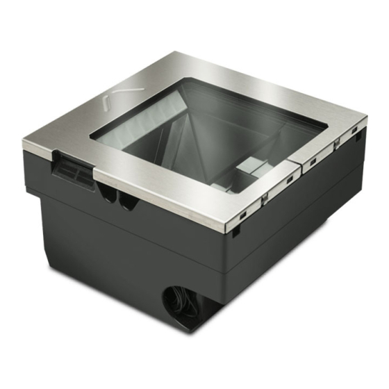
MAGELLAN™ 3510HSI Use this guide to quickly complete installation of the Magellan 3510HSi series of bar code readers, and begin using your scanner. For more details and programming information, reference the Product Reference Guide (PRG), which is available for viewing and download from the Datalogic website listed on the back cover of this manual. -
Page 6: Installation
Installation Figure 2. Connectors POWER HOST Power Host Port USB Aux Port INSTALLATION Connect the scanner to the host (terminal) using the interface (I/F) cable as shown in the following figures. A cable from an older existing installation can be re-used only for RS-232 interfaces. If external power is used/needed, plug the AC Adapter into the AC wall outlet, then connect it to the unit as shown in Figure... - Page 7 Installation Figure 3. USB + Power Cable Power Off the Terminal Terminal (PC) RJ Host Port Power Connector USB + Power Cable Power Off the Terminal (POT) Figure 4. Powered by AC Adapter RS-232 and USB Cables Powered by AC Adapter To Terminal (PC) QUICK REFERENCE GUIDE 3...
- Page 8 Installation Figure 5. USB Cable Type A Power Off the Terminal To Terminal (PC) USB Type A Power Off the Terminal NOTE: This cable (or similar) will not support a USB peripheral. The system must be powered by 12V in order for a peripheral to be attached to the AUX USB PORT.
-
Page 9: How To Scan
How to Scan HOW TO SCAN The scanner is mounted flush with the counter to allow items to be slid or pushed over its top in the direction of the arrow as shown in Figure Face the bar code toward the scanner or direction of scan to optimize the scan rate. - Page 10 How to Scan PRESS FUNCTION COMMENT DURATION Alternatively, the scanner can be awakened by: Momentary (when Wakes scanner from - Moving an object through the scanner is asleep) Sleep Mode scan zone. - Scanning with an attached auxiliary scanner. Press the button momentarily to increase speaker volume.
-
Page 11: Led And Beeper Indicators
LED and Beeper Indicators LED AND BEEPER INDICATORS The scanner’s beeper sounds and its green LED illuminates to indicate various functions or errors on the scanner. The tables that follow list these indications. An exception is that the scanner’s functions are programmable, and may or may not be turned on. -
Page 12: Beeper Indicators
LED and Beeper Indicators Beeper Indicators BEEPER INDICATION COMMENT INDICATION The Power-On LED indication is a configurable feature which can be enabled or disabled. When enabled, this Power On Beep Single beep beep indicates the scanner has finished all its power-up tests and is now ready for operation. -
Page 13: Troubleshooting
If the scanner still does not function properly, consult the Product Reference Guide (PRG) or contact your local supplier or Datalogic Customer Support Services. a. Reading of the various bar code symbologies can be independently enabled or disabled in the scanner. -
Page 14: Error Codes
Programming Mode and return the scanner to normal operation. Select other options and customize your scanner with programming barcodes available in the PRG, or use the Datalogic Scanalyzer utility available on the Datalogic website. NOTE: In the following sections, text shown with a green star indicates a factory default value. -
Page 15: Interface Selection
START / END PROGRAMMING BAR CODES 000105(CR) RS-232 Standard 000112(CR) RS-232 Wincor-Nixdorf 000145(CR) USB-OEM 000135(CR) USB Keyboard 000147(CR) USB COM Interface NOTE: Refer to the Product Reference Guide (PRG) or Datalogic Scanalyzer utility for additional options. QUICK REFERENCE GUIDE 11... -
Page 16: Cell Phone Mode
Programming Cell Phone Mode Enables/disables mobile phone barcode reading. START / END 046700(CR) Cell Phone Mode = Enable (Toggle) 046702(CR) Cell Phone Mode = Enable (Always On) 046701(CR) Cell Phone Mode = Enable (Timer Expiration) MAGELLAN™ 3510HSI... -
Page 17: Cell Mode Percent
Programming Cell Mode Percent Specifies the rate of frames dedicated to reading cell phones. Cell phone mode must be enabled for this to be active. NOTE: Settings above 10% will slow down read performance on printed barcodes. START / END 047100(CR) ... -
Page 18: Cleaning
Cleaning CLEANING Exterior surfaces and scan windows exposed to spills, smudges or debris accumulation require periodic cleaning to assure best performance during scanning. Use a clean, lint-free cloth or paper towel dampened with a nonabrasive, mild, water-based cleaner to wipe away stains, smudges, fingerprints, spills, etc. -
Page 19: Manufacturer Approved Cleaning Materials
Cleaning Manufacturer Approved Cleaning Materials Datalogic recommends the use of the following cleaners on its products. APPROVED CLEANERS • Hydrogen Peroxide (not to exceed a 3% solution) • Chlorine bleach (not to exceed a 0.25% solution) • Mild detergent and water •... -
Page 20: Warranty
Warranty Period. Products are sold on the basis of specifications applicable at the time of manufacture and Datalogic has no obligation to modify or update Products once sold. The Warranty Period shall be three years from the date of shipment by Datalogic, unless otherwise agreed in an applicable writing by Datalogic. -
Page 21: Going Green
Going Green GOING GREEN Thank you for using the bar code mask on the opposite side of this page. This manual has been formatted to minimize the quantity of pages needed to provide the programming bar codes available for this product. -
Page 22: Bar Code Mask
BAR CODE MASK Cut a hole in this page and remove it from the manual as indicated to create a sleeve through which bar codes can be individually viewed and scanned. It is important that only one bar code at a time be presented to the scanner. - Page 24 ©2020 Datalogic S.p.A. and/or its affiliates • All rights reserved • Without limiting the rights under copyright, no part of this docu- mentation may be reproduced, stored in or introduced into a retrieval system, or transmitted in any form or by any means, or for any purpose, without the express written permission of Data- logic S.p.A.
Need help?
Do you have a question about the MAGELLAN 3510HSi and is the answer not in the manual?
Questions and answers