
Subscribe to Our Youtube Channel
Related Manuals for DAKOTA ULTRASONICS MMX-6


Summary of Contents for DAKOTA ULTRASONICS MMX-6
- Page 1 OPERATION MANUAL DAKOTA ULTRASONICS - MMX-6 MULTI-MODE ULTRASONIC THICKNESS GAUGE P/N P-142-0002 Rev 1.10 / 1.11, January 2008 1.800.544.2843 www.calcert.com sales@calcert.com...
- Page 2 Dakota Ultrasonics. Every precaution has been taken in the preparation of this publication. Dakota Ultrasonics assumes no responsibility for errors or omissions. Neither is any liability assumed for damages resulting from the use of information contained herein.
-
Page 3: Table Of Contents
MMX-6 Ultrasonic Thickness Gauge CONTENTS NTRODUCTION PERATION EYPAD ISPLAY RANSDUCER AKING EASUREMENTS ONDITION AND REPARATION OF URFACES ROBE ALIBRATION LARM ULTI RSS232 P RANSDUCER ELECTION A: P PPENDIX RODUCT PECIFICATIONS B: A PPENDIX PPLICATION OTES C: S PPENDIX OUND ELOCITIES OF... - Page 4 Dakota Ultrasonics DISCLAIMER – Very Important! Inherent in ultrasonic thickness measurement is the possibility that the instrument will use the second rather than the first echo from the back surface of the material being measured while in standard pulse-echo mode.
-
Page 5: Introduction
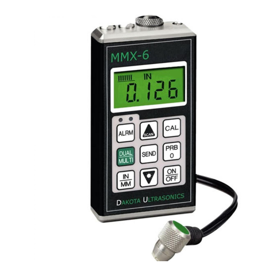
The Dakota Ultrasonics model MMX-6 is a multi-mode Ultrasonic thickness gauge. Based on the same operating principles as SONAR, the MMX-6 is capable of measuring the thickness of various materials with accuracy as high as ± 0.001 inches, or ± 0.01 millimeters. The principle... -
Page 6: Operation
The Keypad This key is used to turn the MMX-6 on and off. When the gauge is turned ON, it will first perform a brief display test by illuminating all of the segments in the display. After one second, the gauge will display the internal software version number. - Page 7 MMX-6 Ultrasonic Thickness Gauge The PRB-0 key is used to "zero" the MMX-6 in much the same way that a mechanical micrometer is zeroed. If the gauge is not zeroed correctly, all of the measurements that the gauge makes may be in error by some fixed value.
- Page 8 Dakota Ultrasonics The UP arrow key has two functions. When the MMX-6 is in calibration mode, this key is used to increase numeric values on the display. An auto- repeat function is built in, so that when the key is held down, numeric values will increment at an increasing rate.
- Page 9 MMX-6 Ultrasonic Thickness Gauge The ALRM key has two functions. By holding down the ALRM key when powering up the MMX-6, the audible beeper will be turned on or off accordingly. After the unit has been turned on, pressing the ALRM key will toggle the alarm mode to the on/off positions and allow the user to enter a nominal thickness value.
-
Page 10: The Display
While the gauge is taking a measurement, six or seven of the bars should be on. If fewer than five bars are on, the MMX-6 is having difficulty achieving a stable measurement, and the thickness value displayed will most likely be erroneous. - Page 11 MMX-6 Ultrasonic Thickness Gauge When the IN symbol is on, the MMX-6 is displaying a thickness value in inches. The maximum thickness that can be displayed is 19.999 inches. When the MM symbol is on, the MMX-6 is displaying a thickness value in millimeters.
-
Page 12: The Transducer
Dakota Ultrasonics The Transducer The transducer is the "business end" of the MMX-6. It transmits and receives ultrasonic sound waves that the MMX-6 uses to calculate the thickness of the material being measured. The transducer connects to the MMX-6 via the attached cable, and two coaxial connectors. When using... -
Page 13: Making Measurements
The Stability Indicator should have six or seven bars darkened, and a number should appear in the display. If the MMX-6 has been properly "zeroed" (see page 12) and set to the correct sound velocity (see page 13), the number in the display will indicate the actual thickness of the material directly beneath the transducer. - Page 14 Occasionally, a small film of couplant will be drawn out between the transducer and the surface as the transducer is removed. When this happens, the MMX-6 may perform a measurement through this couplant film, resulting in a measurement that is larger or smaller than it should be.
-
Page 15: Condition And Preparation Of Surfaces
MMX-6 Ultrasonic Thickness Gauge Condition and Preparation of Surfaces In any ultrasonic measurement scenario, the shape and roughness of the test surface are of paramount importance. Rough, uneven surfaces may limit the penetration of ultrasound through the material, and result in unstable, and therefore unreliable, measurements. -
Page 16: Probe Zero
Check that the wearface of the transducer is clean and free of any debris. 3) The metal probe-disc is on the top end of the MMX-6. Apply a single droplet of ultrasonic couplant to the face of this disc. -
Page 17: Calibration
This will ensure that the instrument is always correctly zeroed. Calibration In order for the MMX-6 to make accurate measurements, it must be set to the correct sound-velocity for the material being measured. Different types of material have different inherent sound-velocities. For example, the velocity of sound through steel is about 0.233 inches-per-microsecond,... - Page 18 1) Make sure the MMX-6 is on and switched to P-E (pulse-echo) mode. Press the Dual-Multi key to toggle modes. Note: The calibration function has been disabled in E-E (echo-echo) mode.
- Page 19 A table of common materials and their sound-velocities can be found in Appendix C. 1) Make sure the MMX-6 is on and switched to P-E (pulse-echo) mode. Press the Dual-Multi key to toggle modes.
- Page 20 (0.233 IN/µs). To achieve the most accurate measurements possible, it is generally advisable to always calibrate the MMX-6 to a sample piece of known thickness. Material composition (and thus, its sound-velocity) sometimes varies from lot to lot and from manufacturer to manufacturer. Calibration to a sample of known thickness will ensure that the gauge is set as closely as possible to the sound velocity of the material to be measured.
- Page 21 1) Make sure the MMX-6 is on and switched to P-E (pulse-echo) mode. Press the Dual-Multi key to toggle modes. Note: The calibration function has been disabled in E-E (echo-echo) mode.
- Page 22 While the MMX-6 excels at making single point measurements, it is sometimes desirable to examine a larger region, searching for the thinnest point. The MMX-6 includes a feature, called Scan Mode, which allows it to do just that. In normal operation, the MMX-6 performs and displays four measurements every second, which is quite adequate for single measurements.
- Page 23 MMX-6 Ultrasonic Thickness Gauge When the MMX-6 is not in calibration mode, press the UP arrow key to turn Scan Mode on and off. A brief message will appear in the display confirming the operation. When the transducer is removed from the material being scanned, the MMX-6 will (after a brief pause) display the smallest measurement it found.
- Page 24 DOWN arrow keys to scroll to the desired nominal alarm value. 5) Press the ALRM key once again to select the nominal value entered. 6) The MMX-6 is now ready to perform measurements using the Alarm feature. Dual-Multi Mode Often times users and inspectors in the field are faced with coated materials such as pipes and tanks.
- Page 25 This same transducer is equally effective when used in pulse-echo mode, eliminating the need to use different transducers for each mode. The new MMX-6 gives you all these features in a simple to use, one button toggle, digital thickness gauge. The following steps outline...
- Page 26 Connecting To a Computer 1) Connect the accessory cable (part# N-306-0010) to the 2 pin jack located on the bottom of the MMX-6, and the 9 pin connector to a serial port on the computer. 2) Start the communications software that will be used to collect the measurements (i.e.
- Page 27 MMX-6 Ultrasonic Thickness Gauge NOTE: Communications software packages generally have the ability to capture the screen data to a common text file. This text file, containing the measurements, can then be imported into any common spreadsheet program (i.e. Excel, Quattro Pro, Lotus123) for further reporting requirements.
-
Page 28: Transducer Selection
Generally speaking, the best transducer for a job is one that sends sufficient ultrasonic energy into the material being measured such that a strong, stable echo is received by the MMX-6. Several factors affect the strength of ultrasound as it travels. These are outlined below: •... - Page 29 MMX-6 Ultrasonic Thickness Gauge Higher frequency ultrasound is absorbed and scattered more than ultrasound of a lower frequency. While it may seem that using a lower frequency transducer might be better in every instance, low frequencies are less directional than high frequencies. Thus, a higher frequency transducer would be a better choice for detecting the exact location of small pits or flaws in the material being measured.
- Page 30 • Through Paint & Coatings The MMX-6 has the ability to measure through and eliminate the thickness of paint or coatings on the surface of metals. While this is a very convenient feature, it must be used with the proper transducers in order to produce favorable results.
-
Page 31: Appendix A: Product Specifications
Dakota Ultrasonics APPENDIX A Product Specifications Physical Weight: 10 ounces Size: 2.5W x 4.75H x 1.25D inches (63.5W x 120.7H x 31.8D mm). Operating Temperature: -20 to 120 °F (-20 to 50 °C) Case: Extruded aluminum body / nickel plated aluminum end caps. -
Page 32: Appendix B: Application Notes
Dakota Ultrasonics APPENDIX B Application Notes • Measuring pipe and tubing When measuring a piece of pipe to determine the thickness of the pipe wall, orientation of the transducers is important. If the diameter of the pipe is larger than approximately 4 inches, measurements should be made with the transducer oriented so that the gap in the wearface is perpendicular (at right angle) to the long axis of the pipe. - Page 33 (refer to page 13) on a sample piece of known thickness, which is at or near the temperature of the material to be measured. This will allow the MMX-6 to correctly calculate the velocity of sound through the hot material.
- Page 34 Dakota Ultrasonics An additional important consideration when measuring laminates, is that any included air gaps or pockets will cause an early reflection of the ultrasound beam. This effect will be noticed as a sudden decrease in thickness in an otherwise regular surface. While this may impede accurate measurement of total material thickness, it does provide the user with positive indication of air gaps in the laminate.
- Page 35 Dakota Ultrasonics APPENDIX C Sound Velocities of some Common Materials M a t e r i a l s o u n d v e l o c i t y i n / u s m / s A l u m i n u m 0 .
-
Page 36: Warranty Information
Dakota Ultrasonics warrants transducers and accessories against such defects for a period of 90 days from receipt by the end user. If Dakota Ultrasonics receives notice of such defects during the warranty period, Dakota Ultrasonics will either, at its option, repair or replace products that prove to be defective. - Page 37 MATERIAL SAFETY DATA SHEET N/A = not applicable or not available (To comply with 29 CFR 1910.1200) SECTION 1 – PRODUCT IDENTIFICATION NFPA Hazardous Materials Identification System (est) Product Name: SOUNDSAFE® Health……………………0 Generic Name: Ultrasonic Couplant Manufacturer: Sonotech, Inc. Flammability…………….0 Reactivity………………..0 SECTION 2 –...
Need help?
Do you have a question about the MMX-6 and is the answer not in the manual?
Questions and answers