
Related Manuals for DAKOTA ULTRASONICS MX-5-C


Summary of Contents for DAKOTA ULTRASONICS MX-5-C
- Page 1 OPERATION MANUAL DAKOTA ULTRASONICS MODEL MX-5 ULTRASONIC THICKNESS GAUGE P/N P-114-0002 Rev 1.90, January 2008...
- Page 2 Dakota Ultrasonics. Every precaution has been taken in the preparation of this publication. Dakota Ultrasonics assumes no responsibility for errors or omissions. Neither is any liability assumed for damages resulting from the use of information contained herein.
- Page 3 MX-5 Ultrasonic Thickness Gauge CONTENTS NTRODUCTION PERATION EYPAD ISPLAY RANSDUCER AKING EASUREMENTS ONDITION AND REPARATION OF URFACES ROBE ALIBRATION , RS232 P LARM RANSDUCER ELECTION A: P PPENDIX RODUCT PECIFICATIONS B: A PPENDIX PPLICATION OTES C: S PPENDIX OUND ELOCITIES OF OMMON ATERIALS ARRANTY...
- Page 4 Dakota Ultrasonics blank page...
- Page 5 The last section provides application notes and a table of sound velocity values for various materials. Dakota Ultrasonics maintains a customer support resource in order to assist users with questions or difficulties not covered in this manual. Customer support may be reached at any of the following: •...
- Page 6 Dakota Ultrasonics blank page...
-
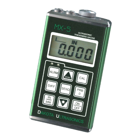
Page 7: Operation
MX-5 Ultrasonic Thickness Gauge OPERATION The MX-5 interacts with the operator through the membrane keypad and the LCD display. The functions of the various keys on the keypad are detailed below, followed by an explanation of the display and its various symbols. - Page 8 Dakota Ultrasonics The PRB-0 key is used to "zero" the MX-5 in much the same way that a mechanical micrometer is zeroed. If the gauge is not zeroed correctly, all of the measurements that the gauge makes may be in error by some fixed value.
- Page 9 MX-5 Ultrasonic Thickness Gauge The UP arrow key has two functions. When the MX-5 is in calibration mode, this key is used to increase numeric values on the display. An auto- repeat function is built in, so that when the key is held down, numeric values will increment at an increasing rate.
- Page 10 Dakota Ultrasonics The ALRM key has two functions. By holding down the ALRM key when powering up the MX-5, the audible beeper will be turned on or off accordingly. After the unit has been turned on, pressing the ALRM key will toggle the alarm mode to the on/off positions and allow the user to enter a nominal thickness value.
- Page 11 MX-5 Ultrasonic Thickness Gauge The Display The numeric portion of the display consists of 4 complete digits preceded by a leading "1", and is used to display numeric values, as well as occasional simple words, to indicate the status of various settings. When the MX-5 is displaying thickness measurements, the display will hold the last value measured, until a new measurement is made.
- Page 12 Dakota Ultrasonics When the IN symbol is on, the MX-5 is displaying a thickness value in inches. The maximum thickness that can be displayed is 19.999 inches. When the MM symbol is on, the MX-5 is displaying a thickness value in millimeters.
- Page 13 The transducer connects to the MX-5 via the attached cable, and two coaxial connectors. When using transducers manufactured by Dakota Ultrasonics, the orientation of the dual coaxial connectors is not critical: either plug may be fitted to either socket in the MX-5.
-
Page 14: Making Measurements
Dakota Ultrasonics This is a top view of a typical transducer. Press against the top with the thumb or index finger to hold the transducer in place. Moderate pressure is sufficient, as it is only necessary to keep the transducer stationary, and the wearface seated flat against the surface of the material being measured. - Page 15 MX-5 Ultrasonic Thickness Gauge If the Stability Indicator has fewer than five bars darkened, or the numbers on the display seem erratic, first check to make sure that there is an adequate film of couplant beneath the transducer, and that the transducer is seated flat against the material.
-
Page 16: Condition And Preparation Of Surfaces
Dakota Ultrasonics Condition and Preparation of Surfaces In any ultrasonic measurement scenario, the shape and roughness of the test surface are of paramount importance. Rough, uneven surfaces may limit the penetration of ultrasound through the material, and result in unstable, and therefore unreliable, measurements. The surface being measured should be clean, and free of any small particulate matter, rust, or scale. -
Page 17: Probe Zero
MX-5 Ultrasonic Thickness Gauge Probe Zero Setting the Zero Point of the MX-5 is important for the same reason that setting the zero on a mechanical micrometer is important. If the gauge is not "zeroed" correctly, all of the measurements the gauge makes will be in error by some fixed number. - Page 18 Dakota Ultrasonics At this point, the MX-5 has successfully calculated it's internal error factor, and will compensate for this value in any subsequent measurements. When performing a "probe-zero", the MX-5 will always use the sound-velocity value of the built-in probe-disc, even if some other velocity value has been entered for making actual measurements.
-
Page 19: Calibration To A Known Thickness
MX-5 Ultrasonic Thickness Gauge Calibration to a known thickness NOTE: This procedure requires a sample piece of the specific material to be measured, the exact thickness of which is known, e.g. from having been measured by some other means. 1) Make sure the M X-5 is on. 2) Perform a Probe-Zero (refer to page 13) 3) Apply couplant to the sample piece. -
Page 20: Calibration To A Known Velocity
Dakota Ultrasonics Calibration to a known velocity NOTE: This procedure requires that the operator know the sound- velocity of the material to be measured. A table of common materials and their sound-velocities can be found in Appendix C. 1) Make sure the M X-5 is on. -
Page 21: Two Point Calibration
MX-5 Ultrasonic Thickness Gauge Two Point Calibration NOTE: This procedure requires that the operator has two known thickness points on the test piece that are representative of the range to be measured. 1) Make sure the M X-5 is on. 2) Perform a Probe-Zero (refer to page 13) 3) Apply couplant to the sample piece. -
Page 22: Scan Mode
Dakota Ultrasonics Scan Mode While the MX-5 excels at making single point measurements, it is sometimes desirable to examine a larger region, searching for the thinnest point. The MX-5 includes a feature, called Scan Mode, which allows it to do just that. -
Page 23: Alarm Mode
MX-5 Ultrasonic Thickness Gauge Alarm Mode The Alarm Mode feature of the MX-5 allows the user to set an audible and visual parameter when taking measurements. When the Alarm Mode is on, the green LED is illuminated. If a measurement falls below a nominal value, set by the user, the red LED will illuminate and the beeper will sound, if enabled. -
Page 24: Differential Mode
Dakota Ultrasonics Alarm Mode 1) Press ON/OFF key to power up the MX-5. 2) Press the ALRM key. ALAr OFF, or ALAr followed by a thickness value and flashing IN (or MM) symbol will be displayed - indicating the alarm mode is enabled. -
Page 25: Rs232 Serial Port
MX-5 Ultrasonic Thickness Gauge Differential Mode 1) Press ON/OFF key to power up the MX-5. 2) Press the DIFF key. DIFF OFF or DIFF followed by a thickness value and flashing IN (or MM) will be displayed. 3) Repeat step 2 to toggle between DIFF OFF or DIFF value and flashing IN. -
Page 26: Connecting To A Computer
Dakota Ultrasonics Connecting To a Computer 1) Connect the accessory cable (part# N-306-0010) to the 2 pin jack located on the bottom of the MX-5, and the 9 pin connector to a serial port on the computer. 2) Start the communications software that will be used to collect the measurements (i.e. -
Page 27: Transducer Selection
MX-5 Ultrasonic Thickness Gauge TRANSDUCER SELECTION The MX-5 is inherently capable of performing measurements on a wide range of materials, from various metals to glass and plastics. Different types of material, however, will require the use of different transducers. Choosing the correct transducer for a job is critical to being able to easily perform accurate and reliable measurements. - Page 28 Dakota Ultrasonics reduce the strength of the waves, and thus, the M X-5's ability to detect the returning echo. Higher frequency ultrasound is absorbed and scattered more than ultrasound of a lower frequency. While it may seem that using a lower frequency transducer might be better in every instance, low frequencies are less directional than high frequencies.
- Page 29 It may be necessary to experiment with a variety of transducers in order to find one that works well for a given job. Dakota Ultrasonics can provide assistance in choosing a transducer, and offers a broad selection of transducers for evaluation in...
- Page 30 Dakota Ultrasonics blank page...
- Page 31 MX-5 Ultrasonic Thickness Gauge APPENDIX A Product Specifications Physical Weight: 10 ounces Size: 2.5W x 4.75H x 1.25D inches (63.5W x 120.7H x 31.8D mm). Operating Temperature: -20 to 120 °F (-20 to 50 °C) Case: Extruded aluminum body / nickel plated aluminum end caps.
- Page 32 Dakota Ultrasonics blank page...
- Page 33 MX-5 Ultrasonic Thickness Gauge APPENDIX B Application Notes • Measuring pipe and tubing When measuring a piece of pipe to determine the thickness of the pipe wall, orientation of the transducers is important. If the diameter of the pipe is larger than approximately 4 inches, measurements should be made with the transducer oriented so that the gap in the wearface is perpendicular (at right angle) to the long axis of the pipe.
- Page 34 Dakota Ultrasonics above this point, the change in sound velocity of the material being measured starts to have a noticeable effect upon ultrasonic measurement. At such elevated temperatures, it is recommended that the user perform a calibration procedure (refer to page 14) on a sample piece of known thickness, which is at or near the temperature of the material to be measured.
- Page 35 MX-5 Ultrasonic Thickness Gauge An additional important consideration when measuring laminates, is that any included air gaps or pockets will cause an early reflection of the ultrasound beam. This effect will be noticed as a sudden decrease in thickness in an otherwise regular surface. While this may impede accurate measurement of total material thickness, it does provide the user with positive indication of air gaps in the laminate.
- Page 36 Dakota Ultrasonics blank page...
- Page 37 MX-5 Ultrasonic Thickness Gauge APPENDIX C Sound Velocities of some Common Materials M a t e r i a l s o u n d v e l o c i t y i n / u s m / s A l u m i n u m 0 .
- Page 38 Dakota Ultrasonics blank page...
-
Page 39: Warranty Information
Dakota Ultrasonics warrants transducers and accessories against such defects for a period of 90 days from receipt by the end user. If Dakota Ultrasonics receives notice of such defects during the warranty period, Dakota Ultrasonics will either, at its option, repair or replace products that prove to be defective. - Page 40 MATERIAL SAFETY DATA SHEET N/A = not applicable or not available (To comply with 29 CFR 1910.1200) SECTION 1 – PRODUCT IDENTIFICATION NFPA Hazardous Materials Product Name: SOUNDSAFE® Identification System (est) Generic Name: Ultrasonic Couplant Health……………………0 Manufacturer: Sonotech, Inc. Flammability…………….0 774 Marine Dr., Bellingham, WA 98225 Reactivity………………..0 (360) 671-9121...
Need help?
Do you have a question about the MX-5-C and is the answer not in the manual?
Questions and answers