Siemens SIMATIC RF185C Operating Instructions Manual
Hide thumbs
Also See for SIMATIC RF185C:
- Operating instructions manual (208 pages) ,
- Operating instructions manual (184 pages) ,
- Operating instructions manual (180 pages)
Table of Contents
Advertisement
SIMATIC Ident
RFID systems
SIMATIC RF185C, RF186C,
RF188C
Operating Instructions
10/2018
C79000-G8976-C512-01
___________________
Introduction
___________________
Security recommendations
___________________
Description
___________________
Mounting
___________________
Connection
___________________
Configuring
___________________
Configuring with the WBM
Programming via SIMATIC
___________________
controller
Programming via the OPC
___________________
UA interface
___________________
Service and maintenance
___________________
Technical data
___________________
Dimension drawings
___________________
Appendix
___________________
Service & Support
1
2
3
4
5
6
7
8
9
10
11
12
A
B
Advertisement
Table of Contents

Related Manuals for Siemens SIMATIC RF185C


Summary of Contents for Siemens SIMATIC RF185C
- Page 1 ___________________ Introduction ___________________ Security recommendations ___________________ SIMATIC Ident Description ___________________ Mounting RFID systems SIMATIC RF185C, RF186C, ___________________ Connection RF188C ___________________ Configuring Operating Instructions ___________________ Configuring with the WBM Programming via SIMATIC ___________________ controller Programming via the OPC ___________________ UA interface...
- Page 2 Note the following: WARNING Siemens products may only be used for the applications described in the catalog and in the relevant technical documentation. If products and components from other manufacturers are used, these must be recommended or approved by Siemens. Proper transport, storage, installation, assembly, commissioning, operation and maintenance are required to ensure that the products operate safely and without any problems.
-
Page 3: Table Of Contents
The "Settings - Communication" menu item ................66 7.3.5 The "Diagnostics - Log" menu item ..................74 7.3.6 The "Diagnostics - Service Log" menu item ................75 7.3.7 The "Edit transponder" menu item ..................78 SIMATIC RF185C, RF186C, RF188C Operating Instructions, 10/2018, C79000-G8976-C512-01... - Page 4 Restoring the factory settings manually ................140 10.5 Module replacement ......................141 10.5.1 Backup configuration data ....................142 10.5.2 Replacing a module ......................144 Technical data ............................. 147 Dimension drawings ..........................149 SIMATIC RF185C, RF186C, RF188C Operating Instructions, 10/2018, C79000-G8976-C512-01...
- Page 5 Table of contents Appendix............................. 151 System planning ........................151 Connecting cables ........................ 152 A.2.1 Standard cables ........................152 A.2.2 Custom assembled cables ....................153 Ordering data ........................154 Service & Support ..........................157 SIMATIC RF185C, RF186C, RF188C Operating Instructions, 10/2018, C79000-G8976-C512-01...
- Page 6 Table of contents SIMATIC RF185C, RF186C, RF188C Operating Instructions, 10/2018, C79000-G8976-C512-01...
-
Page 7: Introduction
You can find information on the readers and optical readers to be connected in the intrinsic safety manual of the respective product family (RF200, RF300, RF600, MV400 and MV500). You can find the current versions of the various manuals on the pages of the Siemens Industry Online Support (https://support.industry.siemens.com/cs/ww/en/ps/14970/man). - Page 8 Do not dispose of the products at public disposal sites. For environmentally compliant recycling and disposal of your electronic waste, please contact a company certified for the disposal of electronic waste or your Siemens representative. Adhere to the various country-specific regulations.
-
Page 9: Security Recommendations
● Keep the software up to date. Keep yourself informed regularly about safety updates for the product. You can find information about this at Link (http://www.siemens.com/industrialsecurity). ● Activate only protocols that you actually need to use the device. ● Limit access to the device using a firewall or rules in an access control list (ACL). - Page 10 ● Enable only the services (protocols) that will actually be used on the device. The same applies to the installed interfaces/ports. Unused ports could be used to access the network downstream from the device. SIMATIC RF185C, RF186C, RF188C Operating Instructions, 10/2018, C79000-G8976-C512-01...
- Page 11 ✓ Yes (simple, Yes (when when config- configured) ured) Explanation of the table: ● Authentication Specifies whether authentication of the communication partner takes place. ● Encryption Specifies whether the transfer is encrypted. SIMATIC RF185C, RF186C, RF188C Operating Instructions, 10/2018, C79000-G8976-C512-01...
- Page 12 Siemens’ products and solutions undergo continuous development to make them more secure. Siemens strongly recommends that product updates are applied as soon as they are available and that the latest product versions are used. Use of product versions that are no longer supported, and failure to apply the latest updates may increase customers’...
-
Page 13: Description
Properties of the communications modules Area of application The SIMATIC RF185C, RF186C and RF188C communications modules are designed for use in all areas of automation. It covers all areas in which SIMATIC Ident RFID readers and optical readers are operated. The application can run at the field level on a controller, on a PC or at the IT level. - Page 14 Description 3.1 Properties of the communications modules You can find additional information on the various RFID devices and optical readers on the Internet on the "Siemens Industry Online Support (https://support.industry.siemens.com/cs/ww/en/ps/14970/man)" page. Features The following features characterize the RF18xC communications modules:...
-
Page 15: User-Specific Procedure
You can find information on this in the section "Configuring with the WBM (Page 53)". 4. Program reader commands You can find information on this in the section "Programming via the OPC UA interface (Page 89)". SIMATIC RF185C, RF186C, RF188C Operating Instructions, 10/2018, C79000-G8976-C512-01... - Page 16 Only the sections with user-specific content, in other words content that is tool/interface-specific, contain these symbols. Sections without these symbols are general and relevant for both areas of application. SIMATIC RF185C, RF186C, RF188C Operating Instructions, 10/2018, C79000-G8976-C512-01...
-
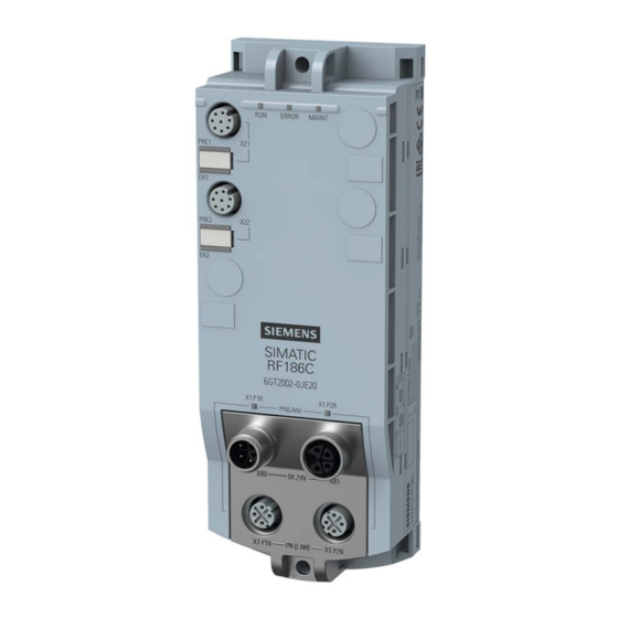
Page 17: Design
Reader interfaces Interface for PROFINET IO (M12, 8-pin, A-coded) (M12, 4-pin, D-coded) ③ ⑦ Reader LEDs Mounting holes and functional ground (PE) ④ PROFINET/Ethernet LEDs Figure 3-2 Design of the communications module SIMATIC RF185C, RF186C, RF188C Operating Instructions, 10/2018, C79000-G8976-C512-01... - Page 18 The RF18xC can then be configured via the TIA Portal or another engineering system. The GSDML file is stored on the communications module and can be downloaded from it using a Web browser. SIMATIC RF185C, RF186C, RF188C Operating Instructions, 10/2018, C79000-G8976-C512-01...
-
Page 19: Mounting
Mounting rules Note Mounting the communications modules Only install the communications module when supply voltages are switched off. You do not have to observe any special rules when installing the communications modules. SIMATIC RF185C, RF186C, RF188C Operating Instructions, 10/2018, C79000-G8976-C512-01... -
Page 20: Mounting The Communications Module
ISO 1207 / DIN EN ISO 1580 If you need washers, use washers conforming to DIN EN ISO 7089 / DIN EN ISO 7090. Cylinder head screw with M4 hex socket accord- ing to DIN EN ISO 4762 SIMATIC RF185C, RF186C, RF188C Operating Instructions, 10/2018, C79000-G8976-C512-01... - Page 21 Fasten the communications module with the screws on a solid level surface. The device must be screwed (≤ 3 Nm) onto the panel at both fastening points (front top and bottom). Figure 4-1 Mounting the RF18xC communications module SIMATIC RF185C, RF186C, RF188C Operating Instructions, 10/2018, C79000-G8976-C512-01...
- Page 22 The following figure shows the upper left fastening point for 2.5 mm wide cable ties. Figure 4-2 Mounting the RF18xC communications module SIMATIC RF185C, RF186C, RF188C Operating Instructions, 10/2018, C79000-G8976-C512-01...
-
Page 23: Connection
Network) in order to ensure compliance with this safety standard. All supply and signal voltages must be safety extra low voltage (SELV/PELV according to IEC 61140). DC 24 V supply: safe (electrical) isolation of extra-low voltage (SELV/PELV according to EN 61140). SIMATIC RF185C, RF186C, RF188C Operating Instructions, 10/2018, C79000-G8976-C512-01... - Page 24 PROFINET IO communication can be structured as a line topology or star topology. Also note the information in the section "Supply voltage and PROFINET IO loop-through (Page 39)". Figure 5-1 Configuration graphic of a line topology Figure 5-2 Configuration graphic of a star topology SIMATIC RF185C, RF186C, RF188C Operating Instructions, 10/2018, C79000-G8976-C512-01...
- Page 25 The connection cable is available in lengths of 2, 5, 10, 20 and 50 m as standard. If necessary, these can be extended. Figure 5-3 Overview of connections SIMATIC RF185C, RF186C, RF188C Operating Instructions, 10/2018, C79000-G8976-C512-01...
-
Page 26: Operation Of The Cm On Grounded/Ungrounded Power Supply
When the communications module is set up with ungrounded reference potential, any interference currents occurring are conducted to functional ground via an internal RC network (no external connection between 1M and FE). SIMATIC RF185C, RF186C, RF188C Operating Instructions, 10/2018, C79000-G8976-C512-01... - Page 27 Fuses for line protection (automatic circuit breaker for 16 A) ④ When setting up the communications module with ungrounded reference potential, there is no connection between 1M, 2M and FE Figure 5-4 Electrical design SIMATIC RF185C, RF186C, RF188C Operating Instructions, 10/2018, C79000-G8976-C512-01...
- Page 28 Isolation monitoring must be provided in the following cases: ● Design of the communications module with ungrounded reference potential ● If hazardous plant states can be expected as a result of faults. SIMATIC RF185C, RF186C, RF188C Operating Instructions, 10/2018, C79000-G8976-C512-01...
-
Page 29: Electrical Design Of The Cm
● Communication interfaces (PROFINET) of the communications module and all other circuit components The following figure shows the potential ratios of the communications module. Figure 5-5 Potential ratios of the communications module SIMATIC RF185C, RF186C, RF188C Operating Instructions, 10/2018, C79000-G8976-C512-01... - Page 30 The following figure shows a configuration with another voltage supply for the communications modules. The different potential groups are highlighted in gray. Figure 5-6 Wiring of the power supply SIMATIC RF185C, RF186C, RF188C Operating Instructions, 10/2018, C79000-G8976-C512-01...
-
Page 31: Connect Cm To Functional Ground (Pe)
You need the following tool to connect to the functional ground: ● Screwdriver Accessories required You need the following accessories to connect to the functional ground: ● Fastening screw (M4) and washer SIMATIC RF185C, RF186C, RF188C Operating Instructions, 10/2018, C79000-G8976-C512-01... - Page 32 Ensure there is a low-impedance connection between the communications module and the conductive base and between the conductive base and functional ground. ① Grounded, metallic base ② Unpainted thread or nut support Figure 5-7 Mounting the CM on a conductive base SIMATIC RF185C, RF186C, RF188C Operating Instructions, 10/2018, C79000-G8976-C512-01...
-
Page 33: Mounting The Cm On A Non-Conductive Base
To connect to functional ground with a non-conductive mounting base, you can need the following accessories: ● Fastening screw (M4) and washer ● Cable lug suitable for M4 screws ● Ground conductor cable (copper braid) with a minimum cross-section of 4 mm SIMATIC RF185C, RF186C, RF188C Operating Instructions, 10/2018, C79000-G8976-C512-01... - Page 34 NOTICE Grounding with non-conductive mounting base Ensure a low impedance connection between the communications module and functional ground. Figure 5-8 Mounting the CM on a non-conductive base / connection to functional ground SIMATIC RF185C, RF186C, RF188C Operating Instructions, 10/2018, C79000-G8976-C512-01...
-
Page 35: Connecting The Communications Module
The pin assignments of the various interfaces are lasered on the side of each communications module at the factory. Requirement Only wire the communications module when the supply voltage is switched off. SIMATIC RF185C, RF186C, RF188C Operating Instructions, 10/2018, C79000-G8976-C512-01... - Page 36 The following tables show the pin assignment for the M12 interface/connector. Table 5- 2 Pin assignment PROFINET IO; M12 socket (4-pin, D-coded) Assignment View of M12 socket, 4-pin Data line TxP Data line RxP Data line TxN Data line RxN SIMATIC RF185C, RF186C, RF188C Operating Instructions, 10/2018, C79000-G8976-C512-01...
- Page 37 Pin assignment reader interface; M12 socket (8-pin, A-coded) Assignment View of M12 socket, 8-pin RS422 RS232 +24 V +24 V -RxD +RxD +TxD +5 V -TxD Functional ground Functional ground (PE) / shield (PE) / shield SIMATIC RF185C, RF186C, RF188C Operating Instructions, 10/2018, C79000-G8976-C512-01...
- Page 38 ① Connector for the reader connection (M12, 8-pin, A-coded) ② Connector for the power supply (M12, 5-pin, L-coded) ③ Connector for PROFINET IO connection (M12, 4-pin, D-coded) Figure 5-10 Connect the plug SIMATIC RF185C, RF186C, RF188C Operating Instructions, 10/2018, C79000-G8976-C512-01...
-
Page 39: Supply Voltage And Profinet Io Loop-Through
If you do not observe the maximum permissible supply current and the cable cross- section required, this may result in the cable isolation and contacts overheating and in the device being damaged. SIMATIC RF185C, RF186C, RF188C Operating Instructions, 10/2018, C79000-G8976-C512-01... -
Page 40: Connecting Cables For The Cms
∅ 1.5 mm Figure 5-12 Voltage drop with a cable cross-section of 1.5 mm To estimate the voltage drop in your communications module, you must add the voltage drops of the cables. SIMATIC RF185C, RF186C, RF188C Operating Instructions, 10/2018, C79000-G8976-C512-01... - Page 41 0.2 V. The value can vary significantly depending on the plug connection or condition. When using a 7 m power cable with ∅ 1.5 mm , the voltage drop is approx. 2.6 V with a 16 A load. SIMATIC RF185C, RF186C, RF188C Operating Instructions, 10/2018, C79000-G8976-C512-01...
- Page 42 Connection 5.6 Connecting cables for the CMs SIMATIC RF185C, RF186C, RF188C Operating Instructions, 10/2018, C79000-G8976-C512-01...
-
Page 43: Configuring
Procedure Proceed as follows to assign a unique device name to the communications module: 1. Open the TIA Portal with "Start > All Programs > Siemens Automation > TIA Portal Vxx". 2. Create a new project. 3. Change to the Project view. - Page 44 12.Select the required node from the list. 13.Now click the "Assign Name" button to assign the PROFINET device name to the communications module. Result: The configured PROFINET device name from the project is assigned to the communications module. SIMATIC RF185C, RF186C, RF188C Operating Instructions, 10/2018, C79000-G8976-C512-01...
-
Page 45: Assigning The Ip Address / Device Name With The Pst
Proceed as follows to assign a new, unique IP address and a unique device name to the communications module: 1. Open the Primary Setup Tool with "Start > All Programs > Siemens Automation > SIMATIC > Primary Setup Tool". 2. In the menu bar under "Settings > Set PG/PC interface..." select the network adapter through which the communications module is connected to the PC and confirm with "OK". - Page 46 Wait until the IP address / the device name has been updated. To display the change, you need to activate the search function using the "Search" icon Result: The communications module is assigned the new IP address and a new device name. SIMATIC RF185C, RF186C, RF188C Operating Instructions, 10/2018, C79000-G8976-C512-01...
-
Page 47: Configuration Via Profinet Io
3. Go to the network view and drag the communications module from the hardware catalog into the project. 4. Connect the communications module with the controller. 5. Configure the communications module (e.g. device name, address range). SIMATIC RF185C, RF186C, RF188C Operating Instructions, 10/2018, C79000-G8976-C512-01... - Page 48 Load configuration to Load configuration data from the STEP 7 project into the communications module. device Save configuration in Save configuration data of the communications module in the current STEP 7 project. project SIMATIC RF185C, RF186C, RF188C Operating Instructions, 10/2018, C79000-G8976-C512-01...
- Page 49 Table 6- 3 Parameters in the "Module parameters" parameter group Parameter Parameter value Default value Description Diagnostic interrupt on Switch diagnostic interrupt messages for the the device communications module on/off SIMATIC RF185C, RF186C, RF188C Operating Instructions, 10/2018, C79000-G8976-C512-01...
- Page 50 No alarms are generated. Hard errors: • Critical hardware errors/faults are reported by the S7 diagnostics. Hard/soft errors: • Critical hardware faults and errors occurring when processing commands are reported by the S7 diagnostics. SIMATIC RF185C, RF186C, RF188C Operating Instructions, 10/2018, C79000-G8976-C512-01...
-
Page 51: Configuration Via Opc Ua
Configuration via OPC UA Configuration of the communications module is not necessary for pure OPC UA work. You can continue directly with configuration via WBM and with programming via OPC UA interface. SIMATIC RF185C, RF186C, RF188C Operating Instructions, 10/2018, C79000-G8976-C512-01... - Page 52 Configuring 6.3 Configuration via OPC UA SIMATIC RF185C, RF186C, RF188C Operating Instructions, 10/2018, C79000-G8976-C512-01...
-
Page 53: Configuring With The Wbm
2. Enter the IP address of the communications module in the address field of your browser. 3. Confirm your entry by pressing the <Enter> key. Result: WBM of the communications module opens. SIMATIC RF185C, RF186C, RF188C Operating Instructions, 10/2018, C79000-G8976-C512-01... - Page 54 Both IP addresses must be located in the same subnet. • Make sure that the connection is not blocked by a firewall. • Use a ping request to check the connection between the PC and the communications module. SIMATIC RF185C, RF186C, RF188C Operating Instructions, 10/2018, C79000-G8976-C512-01...
-
Page 55: The Wbm
When you have created new user profiles you need to log in with one of these user profiles when you restart the WBM. SIMATIC RF185C, RF186C, RF188C Operating Instructions, 10/2018, C79000-G8976-C512-01... - Page 56 The WBM start window is divided into the following areas: ① Toolbar/status bar and log-on ② Menu tree ③ Main window ④ Message area ⑤ Information bar Figure 7-2 Start window of the WBM SIMATIC RF185C, RF186C, RF188C Operating Instructions, 10/2018, C79000-G8976-C512-01...
- Page 57 On the right above the main window there is the status bar with the following information: ● Date/time display of the communications module ● Display of the device status ● Drop-down list for selecting the user interface language ● Log-on/log-off area SIMATIC RF185C, RF186C, RF188C Operating Instructions, 10/2018, C79000-G8976-C512-01...
- Page 58 If you are logged in to the WBM with the "User" role, some menu items can only be used with restrictions. You will find a list of the restrictions in the section "The "User management" menu item (Page 80)". SIMATIC RF185C, RF186C, RF188C Operating Instructions, 10/2018, C79000-G8976-C512-01...
-
Page 59: The Menu Items Of The Wbm
7.3.1 The "Start page" menu item The "Start page" menu item is divided into the following areas. ● Device-specific information ● Project ID ● Address information ● Device clock ● Configuration display SIMATIC RF185C, RF186C, RF188C Operating Instructions, 10/2018, C79000-G8976-C512-01... - Page 60 "PST" and "STEP 7" tools. Via the link "IP Address" you jump to the "System" menu item inn which you can also reassign the IP address. SIMATIC RF185C, RF186C, RF188C Operating Instructions, 10/2018, C79000-G8976-C512-01...
- Page 61 With the "Flash" check box, you can have the LEDs of the connected communications module flash. This enables you to quickly and easily identify the connected communications module. SIMATIC RF185C, RF186C, RF188C Operating Instructions, 10/2018, C79000-G8976-C512-01...
-
Page 62: The "Settings - General" Menu Item
Messages relating to general events: e.g. reader startup, login to the WBM, ... ERRORS Errors and alarm messages of the communications module EVENTS Recording of all tag events COMMANDS Commands of the user application SIMATIC RF185C, RF186C, RF188C Operating Instructions, 10/2018, C79000-G8976-C512-01... -
Page 63: The "Settings - Reader Interface" Menu Item
WBM and cannot be edited. The settings of each interface are identically structured and divided into the following areas: ● Basic settings ● Reader parameters Figure 7-5 The "Settings - Reader Interface" menu item SIMATIC RF185C, RF186C, RF188C Operating Instructions, 10/2018, C79000-G8976-C512-01... - Page 64 In the input box, you can assign a name to the read point (e.g. "Incoming goods gate 5" or "Welding robot 21"). Note that the name is required for addressing the reader via OPC UA. SIMATIC RF185C, RF186C, RF188C Operating Instructions, 10/2018, C79000-G8976-C512-01...
- Page 65 The display can only be reset by turning off the reader. HF power 0.50 ... 5.00 1.00 Setting for the output power of the reader. 1.25 The selectable values depend on the connected device. SIMATIC RF185C, RF186C, RF188C Operating Instructions, 10/2018, C79000-G8976-C512-01...
-
Page 66: The "Settings - Communication" Menu Item
OPC UA server function of the communications module. The "Network interfaces" tab The "Network interfaces" tab is divided into the following areas: ● Network ports ● SNMP ● NTP SIMATIC RF185C, RF186C, RF188C Operating Instructions, 10/2018, C79000-G8976-C512-01... - Page 67 Requirement for port statistics You can read out port statistics using PROFINET diagnostics and via SNMP. Enable the "LLDP" check box to activate the communications log. "LLDP" is a protocol for monitoring the neighborhood. SIMATIC RF185C, RF186C, RF188C Operating Instructions, 10/2018, C79000-G8976-C512-01...
- Page 68 Input box for specifying the intervals at which the communications mod- in seconds ule automatically synchronizes its time. Accept time from Check box to ensure that the communications module also accepts the unsynchronized time from unsynchronized NTP servers. NTP server SIMATIC RF185C, RF186C, RF188C Operating Instructions, 10/2018, C79000-G8976-C512-01...
- Page 69 The "OPC UA" tab The "OPC UA" tab is divided into the following areas: ● Basic settings ● Diagnostic settings ● Security settings ● OPC UA client certificates ● Import OPC UA server certificate SIMATIC RF185C, RF186C, RF188C Operating Instructions, 10/2018, C79000-G8976-C512-01...
- Page 70 The application name is part of the URL of the OPC UA server of the commu- nications module. Minimum Minimum sampling interval at which the communications module samples the sampling interval process data. Range of values: 10 .. 50 ms Default setting: 50 ms SIMATIC RF185C, RF186C, RF188C Operating Instructions, 10/2018, C79000-G8976-C512-01...
- Page 71 • Read point (1-4) Definition of the read point for which the log entries are transmitted. The dis- played names depends on the interface names specified in the "Reader inter- face" menu. SIMATIC RF185C, RF186C, RF188C Operating Instructions, 10/2018, C79000-G8976-C512-01...
- Page 72 OPC UA rights. A user with OPC UA rights can be created via the WBM. The user profile preinstalled in the factory (user name: "admin", password "admin") also has OPC UA rights. SIMATIC RF185C, RF186C, RF188C Operating Instructions, 10/2018, C79000-G8976-C512-01...
- Page 73 With a certificate shown in red, click the "Accept" button to classify the certificate as trustworthy. The cover of the certificate then changes to black. Click the "Delete" button to delete an existing selected certificate. Click the "Update" button to update the list. SIMATIC RF185C, RF186C, RF188C Operating Instructions, 10/2018, C79000-G8976-C512-01...
-
Page 74: The "Diagnostics - Log" Menu Item
7.3.5 The "Diagnostics - Log" menu item The log of the communications module is displayed in the "Diagnostics - Log" menu item. Figure 7-9 The "Diagnostics - Log" menu item SIMATIC RF185C, RF186C, RF188C Operating Instructions, 10/2018, C79000-G8976-C512-01... -
Page 75: The "Diagnostics - Service Log" Menu Item
Log" menu item. The log records internal processes of the communications module and is required for service support by SIEMENS specialists. Only make settings on this page if you are instructed to do so by SIEMENS personnel. The log entries are also evaluated by SIEMENS personnel. - Page 76 Internal frames between Web server and reader CM_DEVICE01 Frames on reader interface 1 (X21) CM_DEVICE03 Frames on reader interface 2 (X22) CM_DEVICE03 Frames on reader interface 3 (X23) CM_DEVICE04 Frames on reader interface 4 (X24) SIMATIC RF185C, RF186C, RF188C Operating Instructions, 10/2018, C79000-G8976-C512-01...
- Page 77 The log read out by the communications module is saved as an *.slf file. The service file contains additional information relevant to Siemens service personnel. With a large number of log entries in the history, it may take several minutes before these are displayed.
-
Page 78: The "Edit Transponder" Menu Item
Read/write In the "Read/write" area, you can read out and overwrite the memory areas. You can access pre-defined addresses (tag fields). Using the parameters, you can adapt the memory area manually. SIMATIC RF185C, RF186C, RF188C Operating Instructions, 10/2018, C79000-G8976-C512-01... - Page 79 Note that, if a connection to the controller is established, the configuration of the readers is performed via the controller. To enable transponder data to be read/written via the WBM, the connected readers must have been initialized via the S7 controller beforehand. SIMATIC RF185C, RF186C, RF188C Operating Instructions, 10/2018, C79000-G8976-C512-01...
-
Page 80: The "User Management" Menu Item
1. Enter your user name in the "User" input box. 2. Enter your password in the "Password" input box. 3. Click the "Log in" button. Result: You are logged in to the WBM and can now set reader parameters. SIMATIC RF185C, RF186C, RF188C Operating Instructions, 10/2018, C79000-G8976-C512-01... - Page 81 To edit a user profile, select the required user name in the list. The selected user name is highlighted in color. Click the "Add new users" button to create a new user. Click the "Delete" button to delete a selected user profile. SIMATIC RF185C, RF186C, RF188C Operating Instructions, 10/2018, C79000-G8976-C512-01...
- Page 82 Note that you as "User" can only transfer changes when the device status of the communications module is "Idle". As an "administrator", you can also transfer changes even when the device status is "Run". SIMATIC RF185C, RF186C, RF188C Operating Instructions, 10/2018, C79000-G8976-C512-01...
-
Page 83: The "System" Menu Item
PC. This page is divided into the following areas: ● Firmware update ● Reset ● IP address ● Certificate ● Device description files SIMATIC RF185C, RF186C, RF188C Operating Instructions, 10/2018, C79000-G8976-C512-01... - Page 84 IP address to the communications module. If you lose your administrator password, you must reset the communications module to the factory settings as described in the section "Restoring the factory settings manually (Page 140)". SIMATIC RF185C, RF186C, RF188C Operating Instructions, 10/2018, C79000-G8976-C512-01...
-
Page 85: The "Help" Menu Item
7.3.10 The "Help" menu item With the "Help" menu item, you can find the manual for the corresponding communications module, "SIMATIC RF185C, RF186C RF188C". SIMATIC RF185C, RF186C, RF188C Operating Instructions, 10/2018, C79000-G8976-C512-01... - Page 86 Configuring with the WBM 7.3 The menu items of the WBM SIMATIC RF185C, RF186C, RF188C Operating Instructions, 10/2018, C79000-G8976-C512-01...
-
Page 87: Programming Via Simatic Controller
Programming via SIMATIC controller This section is intended only for S7 users. You can program and configure the SIMATIC RF185C, RF186C and RF188C communications modules using Ident instructions via a SIMATIC controller. To configure Ident systems using STEP 7 Basic / Professional (TIA Portal), you need appropriate Ident instructions. - Page 88 Programming via SIMATIC controller SIMATIC RF185C, RF186C, RF188C Operating Instructions, 10/2018, C79000-G8976-C512-01...
-
Page 89: Programming Via The Opc Ua Interface
Specification" can be obtained via the "AIM Germany (www.aim-d.de)". All SIMATIC RF18xC communications modules have implemented OPC UA servers with the range of functions for RFID devices defined by "OPC Unified Architecture for AutoID" SIMATIC RF185C, RF186C, RF188C Operating Instructions, 10/2018, C79000-G8976-C512-01... -
Page 90: Supported Methods/Functions
● For an OPC UA client to be able to connect in addition in the event of a PROFINET application as main application, the "Parallel" option needs to be enabled in the WBM. SIMATIC RF185C, RF186C, RF188C Operating Instructions, 10/2018, C79000-G8976-C512-01... - Page 91 Figure 9-2 Node "Objects > DeviceSet" You will find the methods/functions listed below under the following path in the address area of a read point "Objects > DeviceSet > Readpoint_x1". SIMATIC RF185C, RF186C, RF188C Operating Instructions, 10/2018, C79000-G8976-C512-01...
- Page 92 You can refer to the XML device description file "SimaticIdent.RFxxxx.xml" supplied with each communications module for the IDs of the nodes described here. An XML device description file is stored on the communications module and can be downloaded via the SIMATIC RF185C, RF186C, RF188C Operating Instructions, 10/2018, C79000-G8976-C512-01...
- Page 93 Antenna Antenna via which the transponder was accessed with the last command. CurrentPowerLevel Power with which the last command was executed on the transponder. This function is only supported by UHF readers. SIMATIC RF185C, RF186C, RF188C Operating Instructions, 10/2018, C79000-G8976-C512-01...
-
Page 94: Opc Ua Variables
If a client supports events, make sure that these are used. The effects described above cannot occur with events. SIMATIC RF185C, RF186C, RF188C Operating Instructions, 10/2018, C79000-G8976-C512-01... -
Page 95: Executescan
The type definition of "CodeTypes" is "MultiStateDiscrete- Type". This means that the variable has an "Enum" that indicates the supported data types as "Property". Possible values 0: ByteString • 1: String • 2: ScanDataEpc • SIMATIC RF185C, RF186C, RF188C Operating Instructions, 10/2018, C79000-G8976-C512-01... -
Page 96: Rfidsettings
This is a value without a unit and with- out direct reference to the power strength. This variable is only supported by UHF readers. Possible values 0 … 255 SIMATIC RF185C, RF186C, RF188C Operating Instructions, 10/2018, C79000-G8976-C512-01... -
Page 97: Diagnosis
"Parallel" option needs to be enabled in the WBM. In this case, the Diagnostics option is automatically enabled as well. Please note that write access is no longer possible for OPC UA clients as soon as the "Parallel" option is set. SIMATIC RF185C, RF186C, RF188C Operating Instructions, 10/2018, C79000-G8976-C512-01... - Page 98 The prerequisite is that the "Parallel" or "Diagnostics" option is set in the WBM. Possible values S7PNAPI: Access via PROFINET • OpcUaAPI: Access via OPC UA • UserDiagAPI: Access via WBM • SIMATIC RF185C, RF186C, RF188C Operating Instructions, 10/2018, C79000-G8976-C512-01...
- Page 99 • • ScanAsync asyncReadTagIDs • • ReadTag writeTagID • • WriteTag readTagMemory • • KillTag writeTagMemory • • LockTag killTag • • SetTagPassword lockTagBank • • Read getTagStatus • • Write • SIMATIC RF185C, RF186C, RF188C Operating Instructions, 10/2018, C79000-G8976-C512-01...
- Page 100 Outputs the read/written data of the last command. Only possible with commands for reading/writing the transponder memory. The prerequisite is that the "Parallel" or "Diagnostics" option is set in the WBM. Possible values Example (RF300 reader, data type string): 0011223344556677 SIMATIC RF185C, RF186C, RF188C Operating Instructions, 10/2018, C79000-G8976-C512-01...
- Page 101 The prerequisite is that the "Parallel" or "Diagnostics" option is set in the WBM. Possible values Decimal number for the power in [dB] Increment: 0.25 dB • 5.00 ... 33.00 • SIMATIC RF185C, RF186C, RF188C Operating Instructions, 10/2018, C79000-G8976-C512-01...
- Page 102 Outputs the RSSI value with which the last command was exe- cuted on the transponder. This variable is only supported by UHF readers. The prerequisite is that the "Parallel" or "Diagnostics" option is set in the WBM. Possible values 0 ... 255 SIMATIC RF185C, RF186C, RF188C Operating Instructions, 10/2018, C79000-G8976-C512-01...
-
Page 103: Digitalioports
Date_Time ; Type ; Entry ; Command_Type; Sequence_Number ; Readpoint ; EPCID_UID ; PC ; RSSI ; Power 9.2.6 DigitalIOPorts These variables are used to query and set the digital inputs and outputs of the RF18xCI communications module. SIMATIC RF185C, RF186C, RF188C Operating Instructions, 10/2018, C79000-G8976-C512-01... - Page 104 "ON" (1) or "OFF" (0). Outputs whose state is to remain unchanged can be masked out with "x". Example: xx01 Outport03 and Outport02 remain unchanged, Outport01 is switched off, Outport00 is switched on. SIMATIC RF185C, RF186C, RF188C Operating Instructions, 10/2018, C79000-G8976-C512-01...
-
Page 105: Opc Ua Events
"AutoIdDiagnosisEvent" event, which in turn is derived from "BaseEvent" with its properties as defined in the OPC UA standard. Figure 9-3 Derivations of the OPC UA events based on the "BaseEvent" SIMATIC RF185C, RF186C, RF188C Operating Instructions, 10/2018, C79000-G8976-C512-01... -
Page 106: Autoidpresenceevent
"Parallel" or "Diagnostics" option is set in the WBM. In addition to the inherited properties of "BaseEvent", an "RfidLastAccessEvent" also contains the following properties: ● DeviceName ● Client ● Command ● LastAccessResult SIMATIC RF185C, RF186C, RF188C Operating Instructions, 10/2018, C79000-G8976-C512-01... - Page 107 PROFINET (Ident profile): PROFINET (FB 45): INVENTORY WRITE • • WRITE-ID READ • • KILL-TAG INIT • • LOCK-TAG-BANK MDS_STATUS • • PHYSICAL-READ • PHYSICAL-WRITE • FORMAT • TAG-STATUS • • • NEXT • SIMATIC RF185C, RF186C, RF188C Operating Instructions, 10/2018, C79000-G8976-C512-01...
- Page 108 "CommonSettings > Co- deTypes" variable. Description UID or EPC of transponder which was accessed with the last command. Possible values Example (RF300 reader, data type string): 000000005575B67D SIMATIC RF185C, RF186C, RF188C Operating Instructions, 10/2018, C79000-G8976-C512-01...
- Page 109 Possible values Example (RF300 reader, data type string): 0011223344556677 Table 9- 34 CodeTypeRWData Data type CodeTypeDataType Description Shows the set format of "RWData" as String. Possible values RAW:BYTES • RAW:STRING • • SIMATIC RF185C, RF186C, RF188C Operating Instructions, 10/2018, C79000-G8976-C512-01...
- Page 110 Data type String Description Polarization with which the last command was executed on the transponder. This variable is only supported by UHF readers. Possible values Default • Circular • Linear_vertical • Linear_horizontal • SIMATIC RF185C, RF186C, RF188C Operating Instructions, 10/2018, C79000-G8976-C512-01...
-
Page 111: Autoidlastlogentryevent
BrowseName of the read point via which the event was transmitted. Possible values Example: SIMATIC_RF188C (192.168.0.254) The text of the log entry is in the "Message" Property inherited by the "BaseEvent". SIMATIC RF185C, RF186C, RF188C Operating Instructions, 10/2018, C79000-G8976-C512-01... - Page 112 Programming via the OPC UA interface 9.3 OPC UA events SIMATIC RF185C, RF186C, RF188C Operating Instructions, 10/2018, C79000-G8976-C512-01...
-
Page 113: Service And Maintenance
● Via the LED displays of the communications modules ● Via SNMP ● Using WBM ● Via OPC UA ● Via the TIA Portal (STEP 7 Basic / Professional) These alternative methods are described below. SIMATIC RF185C, RF186C, RF188C Operating Instructions, 10/2018, C79000-G8976-C512-01... -
Page 114: Diagnostics Via The Led Display
Indicates that there is a link via Ethernet interface "1" P1 LINK (LK1) • Indicates that there is a link via Ethernet interface "2". P2 LINK (LK2) • Figure 10-1 LED displays of the RF18xC communications module SIMATIC RF185C, RF186C, RF188C Operating Instructions, 10/2018, C79000-G8976-C512-01... - Page 115 PROFINET/Ethernet LED display also flash. The firmware is defective. • There is an error. You can find more information on error messages in the section "Error messages (Page 123)". SIMATIC RF185C, RF186C, RF188C Operating Instructions, 10/2018, C79000-G8976-C512-01...
- Page 116 The flash test is performed for reader identification. At the same time, the LEDs of the status and reader LED display also flash. LED test while the CM is starting up. • A connection is available. • SIMATIC RF185C, RF186C, RF188C Operating Instructions, 10/2018, C79000-G8976-C512-01...
-
Page 117: Diagnostics Via Snmp
In the "Log" menu, you will find all the diagnostics messages of the communications module that have occurred. The log helps SIEMENS specialists to analyze errors. You will find further information on the "Log" in the section "The "Diagnostics - Log" menu item (Page 74)". -
Page 118: Diagnostics Over Opc Ua
STEP 7 Basic / Professional is installed and started, and a project is open. The communications module is connected to the controller or PC via Industrial Ethernet or PROFINET and has been powered up. SIMATIC RF185C, RF186C, RF188C Operating Instructions, 10/2018, C79000-G8976-C512-01... - Page 119 – Under the "Diagnostic status" entry, you can see current status information of the communications module. – Under the "PROFINET interface" entry, you can find status information and further information about the PROFINET interface. Figure 10-2 Display of the diagnostics information of the communications module SIMATIC RF185C, RF186C, RF188C Operating Instructions, 10/2018, C79000-G8976-C512-01...
- Page 120 Diagnostics using the "SIMATIC Ident" technology object Alternatively, you can also diagnose the communications modules using the "SIMATIC Ident" technology object. You can find detailed information on this in the TIA Portal help. SIMATIC RF185C, RF186C, RF188C Operating Instructions, 10/2018, C79000-G8976-C512-01...
-
Page 121: Parameterization Of The Diagnostics
S7 diagnostics. In contrast to the hard errors, errors that arise during command processing are also reported in this case. Please note that messages triggered by command processing are automatically taken back after 3 seconds. SIMATIC RF185C, RF186C, RF188C Operating Instructions, 10/2018, C79000-G8976-C512-01... - Page 122 The event is no longer current, a diagnostic message is output. For events that only exist momentarily, the reset is delayed by 3 seconds. Further information You can find detailed information on diagnostics on PROFINET IO in the manual "SIMATIC PROFINET system description (https://support.industry.siemens.com/cs/ww/en/view/19292127)". SIMATIC RF185C, RF186C, RF188C Operating Instructions, 10/2018, C79000-G8976-C512-01...
-
Page 123: Error Messages
Start address of the command start has been incorrectly set. • Wrong transponder type • The area to be written to is write-protected. • 0xE1FE0400 Initialization error Transponder is unable to execute the initialization command Possible causes: Transponder is defective. • SIMATIC RF185C, RF186C, RF188C Operating Instructions, 10/2018, C79000-G8976-C512-01... - Page 124 The transponder password is incorrect. Access is denied. 0xE1FE8300 The verification of the written transponder data has failed. 0xE1FE8400 General transponder error 0xE1FE8500 The transponder has too little power to execute the command. SIMATIC RF185C, RF186C, RF188C Operating Instructions, 10/2018, C79000-G8976-C512-01...
- Page 125 The selected antenna is not enabled. 0xE2FE8500 The selected frequency is not enabled. 0xE2FE8600 The carrier signal is not activated. 0xE2FE8700 There is more than one transponder in the transmission window. 0xE2FE8800 General radio protocol error SIMATIC RF185C, RF186C, RF188C Operating Instructions, 10/2018, C79000-G8976-C512-01...
- Page 126 The specified tag field of the transponder is unknown. 0xE4FE8A00 General error 0xE4FE8B00 No or bad configuration data/parameters were transferred. Possible causes: You are accessing a read point that is not configured. • SIMATIC RF185C, RF186C, RF188C Operating Instructions, 10/2018, C79000-G8976-C512-01...
- Page 127 Incorrect sequence number order (SN) on the reader/communications module 0xE5FE0200 Incorrect sequence number order (SN) in the Ident profile 0xE5FE0400 Invalid data block number (DBN) on the reader/communications module 0xE5FE0500 Invalid data block number (DBN) in the Ident profile SIMATIC RF185C, RF186C, RF188C Operating Instructions, 10/2018, C79000-G8976-C512-01...
- Page 128 Possible causes: The "AdvancedCmd" block was supplied with an incorrect "CMD". • The "CMD" input of the "AdvancedCmd" block was overwritten. • 0xE6FE0200 Invalid command index (CI) SIMATIC RF185C, RF186C, RF188C Operating Instructions, 10/2018, C79000-G8976-C512-01...
- Page 129 Possible causes / action to be taken: The "WRITE-CONFIG" command is incorrect. • After eliminating the error, execute an "INIT". • Check the parameter "IID_HW_CONNECT". • 0xE6FE8100 A parameter is missing. 0xE6FE8200 The parameter has an invalid format. SIMATIC RF185C, RF186C, RF188C Operating Instructions, 10/2018, C79000-G8976-C512-01...
- Page 130 Timeout during "INIT" (60 seconds according to "TC3WG9") 0xE7FE0900 Command repetition is not supported. 0xE7FE0A00 Error during the transfer of the PDU (Protocol Data Unit). "--" means that the error is not displayed by the LEDs. SIMATIC RF185C, RF186C, RF188C Operating Instructions, 10/2018, C79000-G8976-C512-01...
-
Page 131: Opc Ua Error Messages
REGION_NOT_ All commands: Invalid FOUND_ERROR A parameter of an OPC UA command has an invalid value. Argument / "ReadTag"/"WriteTag" command: good The addressed memory area is not available in the current transponder. SIMATIC RF185C, RF186C, RF188C Operating Instructions, 10/2018, C79000-G8976-C512-01... - Page 132 The verification of the written transponder data has failed. ERROR good RF_COMMUNICATION_ General transponder error ERROR good RF_COMMUNICATION_ The transponder has too little power to execute the command. ERROR good RF_COMMUNICATION_ The transponder signals a CRC error. ERROR SIMATIC RF185C, RF186C, RF188C Operating Instructions, 10/2018, C79000-G8976-C512-01...
- Page 133 A parameter is missing. Argument BadInvalid The parameter has an invalid format. Argument BadInvalid The parameter type is invalid. Argument BadInvalid Unknown parameter. Argument The command or the frame has an invalid format. SIMATIC RF185C, RF186C, RF188C Operating Instructions, 10/2018, C79000-G8976-C512-01...
-
Page 134: Reading Out Error Messages Using The Wbm
In addition, the firmware of the readers connected to the communications module can be updated. The firmware of the readers is updated using the TIA Portal (STEP 7 Basic / Professional V15.1 or higher). These alternative methods are described below. SIMATIC RF185C, RF186C, RF188C Operating Instructions, 10/2018, C79000-G8976-C512-01... -
Page 135: Updating The Firmware Via Wbm
"RUN" LED is lit/flashes green. Note that the startup process takes approx. 1 minute after a firmware update. The updated firmware is active following the restart. SIMATIC RF185C, RF186C, RF188C Operating Instructions, 10/2018, C79000-G8976-C512-01... -
Page 136: Update Firmware Via Tia Portal (Step 7 Basic / Professional)
Reaction: WBM of the communications module opens in your Web browser. Figure 10-3 Firmware update of the communications module 7. Continue the firmware update as described in the section "Updating the firmware via WBM (Page 135)". SIMATIC RF185C, RF186C, RF188C Operating Instructions, 10/2018, C79000-G8976-C512-01... -
Page 137: Updating Firmware Of The Readers Using The Tia Portal (Step 7 Basic / Professional)
4. Select the affected communications module and switch to the device view. 5. Establish an online connection. 6. Right-click on the required reader and select the "Online & diagnostics" entry in the shortcut menu. SIMATIC RF185C, RF186C, RF188C Operating Instructions, 10/2018, C79000-G8976-C512-01... - Page 138 – Note: If the check box is not selected, the new firmware is only activated on the next startup of the communications module. 10.Click the "Start upgrade" button. Result: The firmware is updated. The update process is displayed. SIMATIC RF185C, RF186C, RF188C Operating Instructions, 10/2018, C79000-G8976-C512-01...
-
Page 139: Factory Defaults
The communications module is ready for operation when the "RUN" LED is lit/flashes green. After restarting the communications module, you may have to assign a new IP address or a new device name to the communications module. SIMATIC RF185C, RF186C, RF188C Operating Instructions, 10/2018, C79000-G8976-C512-01... -
Page 140: Restoring The Factory Settings Manually
The communications module is ready for operation when the "RUN" LED is lit/flashes green. After restarting the communications module, you may have to assign a new IP address or a new device name to the communications module. SIMATIC RF185C, RF186C, RF188C Operating Instructions, 10/2018, C79000-G8976-C512-01... -
Page 141: Module Replacement
● With the help of the TIA Portal (STEP 7 Basic / Professional from V15.1) in a STEP 7 project ● With WBM as an *.xml file on your PC These alternative methods are described below. SIMATIC RF185C, RF186C, RF188C Operating Instructions, 10/2018, C79000-G8976-C512-01... -
Page 142: Backup Configuration Data
You can find additional information on programming the blocks and the structure of the configuration data in the section "Config_Upload/Download" of the manual "Ident Profile and Ident Blocks, Standard function for Ident systems". SIMATIC RF185C, RF186C, RF188C Operating Instructions, 10/2018, C79000-G8976-C512-01... - Page 143 These buttons enable you to save configurations, reload them and transfer them to other communications modules. You will find further information on saving and loading the configuration on or from the PC in the section "The WBM (Page 55)". SIMATIC RF185C, RF186C, RF188C Operating Instructions, 10/2018, C79000-G8976-C512-01...
-
Page 144: Replacing A Module
Only wire the SIMATIC controller and the communications modules to be switched on when the voltage is switched off. Make sure that the power supply is turned off when installing/uninstalling the devices. SIMATIC RF185C, RF186C, RF188C Operating Instructions, 10/2018, C79000-G8976-C512-01... - Page 145 ● The new communications module is in the factory state, i.e. no device name and no IP address have been assigned. If the communications module is not in the factory state, the factory settings of the module must be restored. SIMATIC RF185C, RF186C, RF188C Operating Instructions, 10/2018, C79000-G8976-C512-01...
- Page 146 Service and maintenance 10.5 Module replacement SIMATIC RF185C, RF186C, RF188C Operating Instructions, 10/2018, C79000-G8976-C512-01...
-
Page 147: Technical Data
(preassembled cables 2 ... 50 m for other stand- ard cables and custom assembled cables, refer to the section "Connecting cables to the reader") Connectable readers RF185C: 1 x reader • RF186C: 2 x reader • RF188C: 4x reader • SIMATIC RF185C, RF186C, RF188C Operating Instructions, 10/2018, C79000-G8976-C512-01... - Page 148 IEC 61140) 24 V DC supply: Safety (electrical) isolation of low voltage (SELV/PELV acc. to IEC 61140) The power supply must provide the required current of max. 500 mA for transient power failures ≤ 20 ms. SIMATIC RF185C, RF186C, RF188C Operating Instructions, 10/2018, C79000-G8976-C512-01...
-
Page 149: Dimension Drawings
Dimension drawings Figure 12-1 Dimension drawing of an RF18xC communications module All dimensions in [mm]. The figure shows an RF188C communications module. SIMATIC RF185C, RF186C, RF188C Operating Instructions, 10/2018, C79000-G8976-C512-01... - Page 150 Dimension drawings SIMATIC RF185C, RF186C, RF188C Operating Instructions, 10/2018, C79000-G8976-C512-01...
-
Page 151: Appendix
SIMATIC Ident Configuration Guide The SIMATIC Ident Configuration Guide is an ID-specific guide that supports you in selecting the products relevant for your Ident system by clearly displaying all compatible devices and connecting cables. SIMATIC RF185C, RF186C, RF188C Operating Instructions, 10/2018, C79000-G8976-C512-01... -
Page 152: Connecting Cables
Joining more than two cables to form a long cable should be avoided due to the additional contact resistances. Pin assignment Table A- 1 Connecting cable/extension cable M12 ↔ M12 M12 connector (male) M12 connector (female) SIMATIC RF185C, RF186C, RF188C Operating Instructions, 10/2018, C79000-G8976-C512-01... -
Page 153: Custom Assembled Cables
Assignment Core color RS422 RS232 +24 V +24 V Note data sheet provided -RxD by cable manufacturer +RxD +TxD +5 V -TxD Functional Functional ground (PE) / ground (PE) / shield shield SIMATIC RF185C, RF186C, RF188C Operating Instructions, 10/2018, C79000-G8976-C512-01... -
Page 154: Ordering Data
15 m 6XV1801-6DN15 Power supply cable 0.5 m 6XV1801-6GE50 M12-90, L-coded, 4-pin 1.0 m 6XV1801-6GH10 1.5 m 6XV1801-6GH15 2.0 m 6XV1801-6GH20 3.0 m 6XV1801-6GH30 5.0 m 6XV1801-6GH50 10 m 6XV1801-6GN10 15 m 6XV1801-6GN15 SIMATIC RF185C, RF186C, RF188C Operating Instructions, 10/2018, C79000-G8976-C512-01... - Page 155 (10 units) DVD "RFID Systems Software & Documentation" 6GT2080-2AA20 With the L-coded M12 connector (female), only sealing caps with a delivery date of 11/2018 or later can be used. SIMATIC RF185C, RF186C, RF188C Operating Instructions, 10/2018, C79000-G8976-C512-01...
- Page 156 Appendix A.3 Ordering data SIMATIC RF185C, RF186C, RF188C Operating Instructions, 10/2018, C79000-G8976-C512-01...
-
Page 157: Service & Support
Service & Support Industry Online Support In addition to the product documentation, the comprehensive online information platform of Siemens Industry Online Support at the following Internet address: Link 1: (https://support.industry.siemens.com/cs/de/en/) Apart from news, there you will also find: ● Project information: Manuals, FAQs, downloads, application examples etc. - Page 158 Service & Support SIMATIC RF185C, RF186C, RF188C Operating Instructions, 10/2018, C79000-G8976-C512-01...
Need help?
Do you have a question about the SIMATIC RF185C and is the answer not in the manual?
Questions and answers