Siemens SIMATIC RF600 System Manual
Hide thumbs
Also See for SIMATIC RF600:
- System manual (490 pages) ,
- Configuration manual (294 pages) ,
- Compact operating instructions (3 pages)
Table of Contents
Advertisement
Quick Links
SIMATIC RF600
SIMATIC Ident
RFID systems
SIMATIC RF600
System Manual
06/2019
J31069-D0171-U001-A22-7618
Introduction
Safety Information
System overview of
SIMATIC RF600
RF600 system planning
Readers
Antennas
Transponder
Integration into networks
System diagnostics
Accessories
Appendix
1
2
3
4
5
6
7
8
9
10
A
Advertisement
Table of Contents

Related Manuals for Siemens SIMATIC RF600


Summary of Contents for Siemens SIMATIC RF600
- Page 1 SIMATIC RF600 Introduction Safety Information System overview of SIMATIC RF600 SIMATIC Ident RF600 system planning RFID systems SIMATIC RF600 Readers Antennas System Manual Transponder Integration into networks System diagnostics Accessories Appendix 06/2019 J31069-D0171-U001-A22-7618...
- Page 2 Note the following: WARNING Siemens products may only be used for the applications described in the catalog and in the relevant technical documentation. If products and components from other manufacturers are used, these must be recommended or approved by Siemens. Proper transport, storage, installation, assembly, commissioning, operation and maintenance are required to ensure that the products operate safely and without any problems.
-
Page 3: Table Of Contents
Minimum distance to antenna in accordance with ETSI ............21 2.3.3 Minimum distance to antenna in accordance with FCC ............22 System overview of SIMATIC RF600 ....................25 Application areas of RF600 ....................26 System components ....................... 27 Features ..........................30 RF600 system planning......................... - Page 4 Guidelines for electromagnetic compatibility (EMC) .............. 97 4.10.1 Overview ..........................97 4.10.2 What does EMC mean? ......................98 4.10.3 Basic rules ..........................99 4.10.4 Propagation of electromagnetic interference ............... 100 4.10.5 Equipotential bonding ......................102 4.10.6 Cable shielding........................103 SIMATIC RF600 System Manual, 06/2019, J31069-D0171-U001-A22-7618...
- Page 5 SIMATIC RF650R ......................... 145 5.4.1 Description ..........................145 5.4.1.1 Overview ..........................145 5.4.1.2 Ordering data ........................146 5.4.1.3 Pin assignment of the DI/DQ interface (X10 DI/DQ) ............147 5.4.1.4 Switching scheme for the DI/DQ interface ................148 SIMATIC RF600 System Manual, 06/2019, J31069-D0171-U001-A22-7618...
- Page 6 5.6.3 Installation/mounting ......................216 5.6.4 Configuration/integration ...................... 220 5.6.5 Technical specifications ....................... 221 5.6.6 Dimension drawing ......................224 5.6.7 Certificates and approvals ....................225 5.6.7.1 FCC information ........................227 5.6.7.2 IC-FCB information ......................228 SIMATIC RF600 System Manual, 06/2019, J31069-D0171-U001-A22-7618...
- Page 7 Antenna radiation patterns in the FCC frequency band ............283 6.4.6.3 Interpretation of directional radiation patterns ..............288 6.4.7 Technical data ........................289 6.4.8 Dimension drawing ....................... 291 6.4.9 Approvals & certificates ......................292 SIMATIC RF600 System Manual, 06/2019, J31069-D0171-U001-A22-7618...
- Page 8 Bending radii and bending cycles of the cable ..............342 6.8.5 Antenna parameter assignment ................... 343 6.8.6 Antenna patterns ........................345 6.8.6.1 Antenna patterns in the ETSI frequency band ..............346 6.8.6.2 Antenna patterns in the FCC frequency band ..............350 SIMATIC RF600 System Manual, 06/2019, J31069-D0171-U001-A22-7618...
- Page 9 Technical specifications ......................396 Dimension drawing ....................... 398 7.6.5 7.6.6 Certificates and approvals ....................398 SIMATIC RF620T ......................... 399 7.7.1 Characteristics ........................399 7.7.2 Ordering data ........................400 7.7.3 Planning the use ........................400 SIMATIC RF600 System Manual, 06/2019, J31069-D0171-U001-A22-7618...
- Page 10 7.11.2 Ordering data ........................435 7.11.3 Technical specifications ....................... 436 7.11.4 Dimension drawing ......................438 7.11.5 Certificates and approvals ....................440 7.12 SIMATIC RF680T......................... 441 7.12.1 Characteristics ........................441 7.12.2 Ordering data ........................442 SIMATIC RF600 System Manual, 06/2019, J31069-D0171-U001-A22-7618...
- Page 11 Certificates and approvals ....................492 10.2 Power splitter for RF600 systems ..................494 10.2.1 Characteristics ........................494 10.2.2 Ordering data ........................494 10.2.3 Example of a configuration ....................495 10.2.4 Technical specifications ......................495 SIMATIC RF600 System Manual, 06/2019, J31069-D0171-U001-A22-7618...
- Page 12 Overview ..........................497 10.3.2 Ordering data ........................497 10.3.3 Mounting with the SIMATIC antenna holder ................ 497 10.3.4 Dimension drawing ......................499 Appendix ............................. 503 Certificates & approvals ....................... 503 Service & support ......................... 506 SIMATIC RF600 System Manual, 06/2019, J31069-D0171-U001-A22-7618...
-
Page 13: Introduction
Scope of this documentation This documentation is valid for all supplied versions of the SIMATIC RF600 system and describes the state of delivery as of 06/2019. If you are using older firmware versions, please refer to the 08/2011 edition of the documentation. -
Page 14: Abbreviations And Naming Conventions
Introduction 1.2 Abbreviations and naming conventions History Currently released versions of the SIMATIC RF600 system manual: Edition Comment 11/2005 First edition 10/2015 Approval for the readers RF650R, RF680R, and RF685R 12/2015 New antennas RF650A and RF680A 10/2016 Revision of the transponder sections... -
Page 15: Safety Information
D not open the device when energized. NOTICE Alterations not permitted Alterations to the devices are not permitted. Failure to observe this requirement shall constitute a revocation of the radio equipment approval, CE approval and manufacturer's warranty. SIMATIC RF600 System Manual, 06/2019, J31069-D0171-U001-A22-7618... - Page 16 Repairs may only be carried out by authorized qualified personnel. Unauthorized opening of and improper repairs to the device may result in substantial damage to equipment or risk of personal injury to the user. SIMATIC RF600 System Manual, 06/2019, J31069-D0171-U001-A22-7618...
- Page 17 The antenna RF650A must not be installed in the (protected) outdoor area. ① Antenna or reader ② Protected area (indoors); grounding is not necessary here. ③ Protected area (outdoors); grounding is not necessary here. Figure 2-1 Mounting the reader in protected areas SIMATIC RF600 System Manual, 06/2019, J31069-D0171-U001-A22-7618...
- Page 18 Siemens’ products and solutions undergo continuous development to make them more secure. Siemens strongly recommends that product updates are applied as soon as they are available and that the latest product versions are used. Use of product versions that are no longer supported, and failure to apply the latest updates may increase customers’...
-
Page 19: Safety Instructions For Third-Party Antennas As Well As For Modifications To The Rf600 System
NOTICE Loss of warranty If you cause defects on the SIMATIC RF600 system by improperly installing or exchanging system expansions, the warranty becomes void. Note Loss of validity for type tests and certificates SIMATIC RFID products comply with the salient safety specifications to VDE/DIN, IEC, EN, UL and CSA. -
Page 20: Safety Distance To Transmitter Antenna
User responsibility for modified product As a user of the modified product, you accept responsibility for use of the complete RFID product comprising both SIMATIC RF600 components and third-party RFID components. This particularly applies to modification or replacement of: • Antennas •... -
Page 21: Minimum Distance To Antenna In Accordance With Etsi
If the transmitter power is set lower than the highest permissible value (2 watts ERP), the "safety distance" reduces correspondingly. The values for this are as follows: Radiated power ERP [W] Safety distance to transmitter antenna [m] 0.24 0.17 0.12 SIMATIC RF600 System Manual, 06/2019, J31069-D0171-U001-A22-7618... -
Page 22: Minimum Distance To Antenna In Accordance With Fcc
The SIMATIC RF685R (ETSI) reader has a maximum radiated power of 2 W ERP. The safety clearance is therefore at least 0.24 m. When using Siemens products and with suitable configuration via the WBM, the high limits cannot be exceeded. - Page 23 The SIMATIC RF685R (CC) reader has a maximum transmit power of 2 W. This means that the safety distance is at least 0.12 m. When using Siemens products and with suitable configuration via the WBM, the high limits cannot be exceeded.
- Page 24 Safety Information 2.3 Safety distance to transmitter antenna SIMATIC RF600 System Manual, 06/2019, J31069-D0171-U001-A22-7618...
-
Page 25: System Overview Of Simatic Rf600
System overview of SIMATIC RF600 SIMATIC RF600 is an identification system that operates in the UHF range. UHF technology supports large write/read distances with passive transponders. The general automation and IT structure of a company is shown in the following figure. This comprises several different levels that are described in detail below. -
Page 26: Application Areas Of Rf600
System overview of SIMATIC RF600 3.1 Application areas of RF600 of the company (business administration control). MES solutions are used, for example, for defining and performing production processes. Application areas of RF600 RFID (radio frequency identification) permits continuous identification, tracking and documentation of all delivered, stocked and shipped goods in the incoming goods, warehouse, production, production logistics and distribution departments. -
Page 27: System Components
System overview of SIMATIC RF600 3.2 System components System components Table 3- 1 System components of the RF600 product series Product photo Description SIMATIC RF610R RF610R reader is suitable for applications in production logistics and distribution. It is charac- terized by a very compact size - with reduced transmit power – as well as an internal anten- It is integrated for distribution via Ethernet with the XML protocol or OPC UA. - Page 28 System overview of SIMATIC RF600 3.2 System components Product photo Description SIMATIC RF650M The RF650M mobile reader expands the identification system RF600 with a powerful handheld terminal for applications in the areas of logistics, production and service. In addi- tion, it is an indispensable aid for commissioning and testing.
- Page 29 System overview of SIMATIC RF600 3.2 System components Product photo Description SIMATIC RF660A SIMATIC RF660A is a powerful circular antenna for production and logistics applications. SIMATIC RF680A SIMATIC RF680A is an antenna whose polarization can be changed (circular, linear horizon- tal or linear vertical) of medium size for universal use in industrial applications in production and logistics.
-
Page 30: Features
System overview of SIMATIC RF600 3.3 Features Features The RF600 identification system has the following performance features: Table 3- 2 Features of the RF600 RFID system Type Contactless RFID (Radio Frequency IDentification) system in the UHF band Transmission frequency ETSI: 865 to 868 MHz •... - Page 31 System overview of SIMATIC RF600 3.3 Features Table 3- 4 Characteristics of the RF650M mobile reader Transmission frequency ETSI: 865 to 868 MHz • FCC: 902 to 928 MHz • CMIIT: 920 to 925 MHz • Read/write distance Standards ISO 18000-63...
- Page 32 System overview of SIMATIC RF600 3.3 Features SIMATIC RF600 System Manual, 06/2019, J31069-D0171-U001-A22-7618...
-
Page 33: Rf600 System Planning
● EMC Directives Possible system configurations The SIMATIC RF600 system is characterized by a high level of standardization of its components. This means that the system follows the TIA principle throughout: Totally Integrated Automation. It provides maximum transparency at all levels with its reduced number of interfaces. - Page 34 - the SIMATIC RF650A antennas can also be used. Because the readers are connected in a bus topology, wiring requirements are reduced. The reader reads the information from the transponders on the transport containers and forwards it to the SIMATIC S7 controller. SIMATIC RF600 System Manual, 06/2019, J31069-D0171-U001-A22-7618...
- Page 35 , the reader reads the information from the transponder on the transport containers and forwards it to the SIMATIC S7 controller. ③ The SIMATIC S7 controls the separator of the conveyor system depending on the transponder information. SIMATIC RF600 System Manual, 06/2019, J31069-D0171-U001-A22-7618...
-
Page 36: Scenario For Workpiece Identification
This "triggering" can be implemented with light barriers or beros. This procedure reduces mutual influence/disruption of the read points and increases the SIMATIC RF600 System Manual, 06/2019, J31069-D0171-U001-A22-7618... -
Page 37: Goods Tracking Scenario
The reader reads the information from the transponders on the goods and forwards it to the user application, which checks the status of the goods. The traffic light is set to green or red depending on whether the goods are released. SIMATIC RF600 System Manual, 06/2019, J31069-D0171-U001-A22-7618... -
Page 38: Scenario Incoming Goods, Distribution Of Goods And Outgoing Goods
This data is read out and passed on. The goods supplied on the pallets are processed in the factory and then exit the factory through the outgoing goods gate. Figure 4-5 Scenario: Incoming goods, distribution of goods and outgoing goods SIMATIC RF600 System Manual, 06/2019, J31069-D0171-U001-A22-7618... -
Page 39: Antenna Configurations
The following information about the antenna configuration only applies to the antennas of the RF600 family. Refer to the Guidelines for selecting RFID UHF antennas (Page 51) for information on the configuration of third-party antennas. SIMATIC RF600 System Manual, 06/2019, J31069-D0171-U001-A22-7618... -
Page 40: Antenna Configuration Example
4 m. The diagram shows a configuration with three antennas. Up to four antennas can be used depending on the local conditions. Figure 4-6 Example of an antenna configuration with three antennas SIMATIC RF600 System Manual, 06/2019, J31069-D0171-U001-A22-7618... -
Page 41: Possibilities And Application Areas For Antenna Configurations
① Transponder SIMATIC RF600 System Manual, 06/2019, J31069-D0171-U001-A22-7618... - Page 42 The transponder is located in the radiation field of two an- tennas; for reliable transponder reading, the height of the transponders above floor level must therefore be known with reasonable accuracy. ① Transponder SIMATIC RF600 System Manual, 06/2019, J31069-D0171-U001-A22-7618...
- Page 43 Preferred for the identification of goods at loading gates: The transponder is located in the radiation field of all four antennas, so the transponder position for reliable tag identification is more flexible than in configuration 2. ① Transponder SIMATIC RF600 System Manual, 06/2019, J31069-D0171-U001-A22-7618...
- Page 44 One of the antenna is located on the floor and radiates vertically upwards in the direction of the conveyor belt. A relatively high reading reliability is achieved due to the use of four anten- nas. ① Transponder SIMATIC RF600 System Manual, 06/2019, J31069-D0171-U001-A22-7618...
-
Page 45: Transponder Orientation In Space
Parallel transponder alignment Large reading range The probability of identification of the tran- sponders is at a maximum. Vertical transponder alignment Minimal reading range The probability of identification of the tran- sponders is at a minimum. SIMATIC RF600 System Manual, 06/2019, J31069-D0171-U001-A22-7618... -
Page 46: Specified Minimum And Maximum Spacing Of Antennas
Between the antenna and liquids or metals, a minimum distance of 50 cm should be kept to. The distance between the antenna and the floor should also be at least 50 cm. Figure 4-7 Minimum distance to the environment SIMATIC RF600 System Manual, 06/2019, J31069-D0171-U001-A22-7618... -
Page 47: Reciprocal Influence Of Read Points
RF640A/RF642A with RF650A/RF680A with RF660A Back to back 1.0 m 0.3 m 0.5 m Pointing at each other 2.0 m 2.0 m 2.0 m Next to each other 2.0 m 0.5 m 0.8 m SIMATIC RF600 System Manual, 06/2019, J31069-D0171-U001-A22-7618... -
Page 48: Read And Write Range
The higher the absorption of the surrounding material, the smaller the reading range. Manufacturing quality of the tran- The better the transponder has been matched to the oper- sponders ating frequencies during manufacturing, the greater the reading range. SIMATIC RF600 System Manual, 06/2019, J31069-D0171-U001-A22-7618... -
Page 49: Static/Dynamic Mode
The following overview shows which environments are suitable for which read or write mode: Operating mode Read Write Static Recommended in normal UHF Recommended in normal UHF environments environments Dynamic Recommended under difficult Not recommended in difficult UHF conditions UHF environments SIMATIC RF600 System Manual, 06/2019, J31069-D0171-U001-A22-7618... -
Page 50: Operation Of Several Readers Within Restricted Space
A channel plan can be created for ETSI and CMIT readers; for FCC readers, it is assumed that the probability of two readers accidentally using the same channel is very low. SIMATIC RF600 System Manual, 06/2019, J31069-D0171-U001-A22-7618... -
Page 51: Frequency Hopping
This section is aimed at configuration engineers who thoroughly understand and wish to carry out the selection and installation of an antenna or a cable for the SIMATIC RF600 system. The various antenna and cable parameters are explained, and information is provided on the criteria you must particularly observe. -
Page 52: General Application Planning
Overview of the total SIMATIC RF600 system and its influencing factors In the following graphic you can see the design of a SIMATIC RF600 reader with connected antenna and the influencing factors. The influencing factors affect the radiated power output. -
Page 53: Types Of Antenna
With the readers, the parameters for the transmit/radiated power, antenna gain and cable loss (user-defined) are set using the WBM. In the WBM, you can select the Siemens products being used from a drop-down list quickly and easily, and the values and their effect on the transmit/radiated power are calculated directly. - Page 54 You must use connectors and adapters of the type "Reverse Polarity R-TNC" (male connector) for your antenna cables to ensure correct connection to the RF600 reader interface. Figure 4-10 Thread standardization You can find more information in the catalog data of your cable vendor. SIMATIC RF600 System Manual, 06/2019, J31069-D0171-U001-A22-7618...
-
Page 55: Minimum Distances And Maximum Ranges
The polarization of the antenna plays a decisive role. The antennas are distinguished according the following types: ● Linear antennas: RF615A, RF620A, RF642A ● Circular antennas: RF640A, RF660A, RF650A ● Antennas that can be switched over (linear/circular): RF680A SIMATIC RF600 System Manual, 06/2019, J31069-D0171-U001-A22-7618... - Page 56 Changing the transponder angle within the x-y plane has no effect on the range. ① Circular antenna RF640A, RF650A, RF660A or RF680A ② Transponder Figure 4-11 Possible transponder alignment with circular antennas SIMATIC RF600 System Manual, 06/2019, J31069-D0171-U001-A22-7618...
- Page 57 ② Transponder Figure 4-12 Possible transponder alignment with linear antennas Note Optimum transponder position/alignment Depending on the electromagnetic properties of the environment, the optimum transponder position and alignment may differ from those shown above. SIMATIC RF600 System Manual, 06/2019, J31069-D0171-U001-A22-7618...
-
Page 58: Effects Of The Materials Of The Mounting Surfaces On The Range
150 x 150 mm. You will find more detailed information on antenna gain in the subsections of the section "Antenna patterns (Page 257)". SIMATIC RF600 System Manual, 06/2019, J31069-D0171-U001-A22-7618... -
Page 59: Maximum Read/Write Ranges Of Transponders
– RF615A and RF620A: Mounted on metal. – RF680A: Circular polarization ● Room temperature of approx. 20 - 25 °C ● Low-reflection environment; Ranges may be smaller or larger depending on the ambient conditions. SIMATIC RF600 System Manual, 06/2019, J31069-D0171-U001-A22-7618... - Page 60 RF620A with RF640A with RF642A with RF650A with RF660A with RF680A SIMATIC RF685R with internal antenna SIMATIC RF680R SIMATIC RF685R with RF615A with RF620A with RF640A with RF642A with RF650A with RF660A with RF680A SIMATIC RF600 System Manual, 06/2019, J31069-D0171-U001-A22-7618...
- Page 61 RF620A with RF640A with RF642A with RF650A with RF660A with RF680A SIMATIC RF685R with internal antenna SIMATIC RF680R SIMATIC RF685R with RF615A with RF620A with RF640A with RF642A with RF650A with RF660A with RF680A SIMATIC RF600 System Manual, 06/2019, J31069-D0171-U001-A22-7618...
- Page 62 SIMATIC RF685R with internal antenna SIMATIC RF680R SIMATIC RF685R with RF615A with RF620A with RF640A with RF642A with RF650A with RF660A with RF680A Mounting on metal. Mounting surface with a minimum diameter of 150 mm. SIMATIC RF600 System Manual, 06/2019, J31069-D0171-U001-A22-7618...
- Page 63 RF680A Mounting on a non-metallic surface. Mounting on metal is only permitted in combination with a spacer. Mounting on metal Mounting surface with a minimum diameter of 150 mm, for the RF630T 300 mm. SIMATIC RF600 System Manual, 06/2019, J31069-D0171-U001-A22-7618...
- Page 64 Maximum write ranges Depending on the transponder type, the reader antenna requires more power for writing than for reading data. When writing, the maximum range reduces by approximately 30 % compared with the read range. SIMATIC RF600 System Manual, 06/2019, J31069-D0171-U001-A22-7618...
-
Page 65: Minimum Distances Between Antennas And Transponders
Influence of conducting walls on the range If there are metallic (reflecting) surfaces in the immediate vicinity of the transponder, this can have a negative effect on the write/read range. Test the environmental conditions before using the transponder. SIMATIC RF600 System Manual, 06/2019, J31069-D0171-U001-A22-7618... -
Page 66: Environmental Conditions For Transponders
Due to these electromagnetic characteristics, it is extremely difficult in the multiple-reflection environment that is usually found in real environments on site to determine propagation paths and field strengths for a particular location. SIMATIC RF600 System Manual, 06/2019, J31069-D0171-U001-A22-7618... -
Page 67: Influence Of Metals
If the reflected energy becomes too strong in the receive path of the reader, this activates a protective circuit that shows itself as an antenna error without there actually being an error in the configuration or a defect on the antenna. SIMATIC RF600 System Manual, 06/2019, J31069-D0171-U001-A22-7618... -
Page 68: Influence Of Liquids And Non-Metallic Substances
If a DECT station that is transmitting in the 2 GHz band, for example, is located in the receiving range of an antenna of the RF600 system, the performance of the write and read access to the transponder may be reduced. SIMATIC RF600 System Manual, 06/2019, J31069-D0171-U001-A22-7618... -
Page 69: Planning And Installation Of Uhf Read Points
(according to the IEEE 802.11 standard). The actual RSSI value depends on numerous parameters: ● transponder type used, ● chip used in the transponder, ● connected antenna, ● transmit power, SIMATIC RF600 System Manual, 06/2019, J31069-D0171-U001-A22-7618... - Page 70 Identification situation with two transponders in an ideal radio/antenna field ② Identification situation with two transponders in a real radio/antenna field with reflections that can lead to obliteration and overshoots Figure 4-15 Propagation of UHF RFID antenna fields SIMATIC RF600 System Manual, 06/2019, J31069-D0171-U001-A22-7618...
- Page 71 This restriction does not apply with circular polarization. Circular antennas can also be used with differing alignments of the transponder and achieve constant results (e.g. RF680A or RF685R). It has been shown that with a defined transponder alignment, the linear antenna normally produces the best results. SIMATIC RF600 System Manual, 06/2019, J31069-D0171-U001-A22-7618...
-
Page 72: Implementation Of Uhf Rfid Installations
A product needs to be processed by different machines along the production line. The information for this is contained on a transponder attached to the product that must be read out at each machine. Possible configuration: RF685R with integrated adaptive antenna SIMATIC RF600 System Manual, 06/2019, J31069-D0171-U001-A22-7618... -
Page 73: Test Phase
The final position of the transponder should only be decided after an adequately intensive test phase so that suitable variations can be tried out if errors occur. SIMATIC RF600 System Manual, 06/2019, J31069-D0171-U001-A22-7618... -
Page 74: Setting Up Read Points
The read point setup described in this section is performed using the Web Based Management (WBM) and applies to the RF600 readers. You can find a detailed description of the WBM in the configuration manual "SIMATIC RF600 (https://support.industry.siemens.com/cs/ww/en/ps/15081/man)". Adjust antennas Follow the steps below to optimize the antenna alignment: 1. - Page 75 In this case, the following applies: "as much as necessary, as little as possible". In the "Settings - Activation power" menu item, you can find the optimum radiated power for reliable transponder access. SIMATIC RF600 System Manual, 06/2019, J31069-D0171-U001-A22-7618...
- Page 76 3. Click the "Apply" button to transfer the value entered in the "Radiated power" input box of the "Settings - Read points" menu item. 4. Click the symbol to transfer the configuration to the reader. SIMATIC RF600 System Manual, 06/2019, J31069-D0171-U001-A22-7618...
-
Page 77: Dealing With Field Disturbances
Approaches to solutions: – Varying the antenna polarization – Using additional antennas – Use of UHF algorithms – Changing the antenna position – Shielding measures – Use antennas with a lower gain SIMATIC RF600 System Manual, 06/2019, J31069-D0171-U001-A22-7618... -
Page 78: Measures For Eliminating Field Disturbances
Where possible, avoid the use of metal structures (for example housings) and use plastic instead. Even with reader-to-reader influence, you can use absorbent plates or shielding sheets. SIMATIC RF600 System Manual, 06/2019, J31069-D0171-U001-A22-7618... - Page 79 Use of UHF algorithms In the "Settings - Read points" menu item of the WBM, you will find various "Tools" in the "Algorithms" area that you can use to improve the read/write reliability. SIMATIC RF600 System Manual, 06/2019, J31069-D0171-U001-A22-7618...
-
Page 80: Chemical Resistance Of The Readers And Transponders
Aluminum Fiber-optic cable Makrolon®2405 Decorative membrane Autotex V200 Socket Brass (copper alloy) CuZn40Pb2 Non-relevant component for resistance of complete housing In case of questions please contact Siemens Support (section "Service & support (Page 506)"). SIMATIC RF600 System Manual, 06/2019, J31069-D0171-U001-A22-7618... -
Page 81: Pocan Cf2200
Olive oil ++++ Butter ++++ Motor oils HD, hydraulic oils ++++ Gearbox oils (mild-blend) ++++ Lubricating greases (roller bearing ++++ greases DIN 51825) Lubricating greases (basis: ester oils, ++++ diester oils, phosphate ester, synthetic oil) SIMATIC RF600 System Manual, 06/2019, J31069-D0171-U001-A22-7618... - Page 82 ++++ Urea ++++ Trichlorethylene ○ Nitrobenzene ++++ Hydrogen peroxide ++++ Explanation of the rating ++++ Resistant Practically resistant Conditionally resistant Less resistant ○ Not resistant conc. Concentrated solution Water solution c. s. Cold saturated SIMATIC RF600 System Manual, 06/2019, J31069-D0171-U001-A22-7618...
-
Page 83: Transponder
The following table provides an overview of the chemical resistance of the transponder made of acrylonitrile/butadiene/styrene (ABS). Table 4- 13 Resistance to chemicals - ABS Substance Test conditions Evaluation Concentration [%] Temperature [°C] Acetone Alcohols Gasoline ++++ Aliphatic hydrocarbons ++++ SIMATIC RF600 System Manual, 06/2019, J31069-D0171-U001-A22-7618... -
Page 84: Polyamide 12 (Pa12)
10 % 60 ℃ ++++ Benzene 20 ℃ ++++ 60 ℃ Bleach solution (12.5% effective chlo- 20 ℃ rine) Butane, gas, liquid 60 ℃ ++++ Butyl acetate (acetic acid butyl ester) 60 ℃ ++++ SIMATIC RF600 System Manual, 06/2019, J31069-D0171-U001-A22-7618... - Page 85 60 ℃ ++++ Mercury 60 ℃ ++++ Nitric acid 10 % 20 ℃ Hydrochloric acid 10 % 20 ℃ Sulfur dioxide 60 ℃ ++++ Sulfuric acid 25 % 20 ℃ 10 % 20 ℃ SIMATIC RF600 System Manual, 06/2019, J31069-D0171-U001-A22-7618...
-
Page 86: Polyamide 6.6 (Pa 6.6)
Aliphatic hydrocarbons ++++ Aromatic hydrocarbons ++++ Weak alkaline solutions Strong alkaline solutions ○ Weak mineral acids Strong mineral acids ○ Perchloroethylene ++++ Mineral lubricants ++++ Oxidizing acids ○ Weak organic acids Strong organic acids ○ SIMATIC RF600 System Manual, 06/2019, J31069-D0171-U001-A22-7618... -
Page 87: Polyamide 6.6 Gf (Pa 6.6 Gf)
Ethyl alcohol, w., undenaturated 40 % 20 ℃ ++++ Formaldehyde 30 % 20 ℃ ++++ FORMALIN 20 ℃ ++++ Glycerine 20 ℃ ++++ Isopropanol 60 ℃ ++++ Potassium hydroxide, w. 10 ... 15 % 20 ℃ SIMATIC RF600 System Manual, 06/2019, J31069-D0171-U001-A22-7618... - Page 88 1 ... 4 20 ℃ ++++ Nothing specified for stainless steel Explanation of the rating ++++ Resistant Practically resistant Conditionally resistant Less resistant ○ Not resistant conc. Concentrated solution Water solution c. s. Cold saturated SIMATIC RF600 System Manual, 06/2019, J31069-D0171-U001-A22-7618...
-
Page 89: Polyethylene Terephthalate (Pet)
20 ℃ ++++ Potassium permanganate 10 % 20 ℃ ++++ Copper sulfate 10 % 20 ℃ ++++ Methanol 100 % 20 ℃ ++++ Methyl ethyl ketone 100 % 20 ℃ ++++ Milk 20 ℃ ++++ SIMATIC RF600 System Manual, 06/2019, J31069-D0171-U001-A22-7618... - Page 90 20 ℃ ++++ 20 ℃ ++++ Xylene 10 % 20 ℃ ++++ Zinc chloride 20 ℃ ++++ Explanation of the rating ++++ Resistant Practically resistant Conditionally resistant Less resistant ○ Not resistant conc. Concentrated solution SIMATIC RF600 System Manual, 06/2019, J31069-D0171-U001-A22-7618...
-
Page 91: Polypropylene (Pp)
Boric acid, w. 10 % 50 °C ++++ Brake fluid 50 °C ++++ Bromine 20 ℃ ○ Butane, gas, liquid technically clean 50 °C ++++ Butyl acetate (acetic acid butyl ester) 20 ℃ 50 °C ○ SIMATIC RF600 System Manual, 06/2019, J31069-D0171-U001-A22-7618... - Page 92 Potassium hydroxide 10 / 50 50 °C ++++ Silicic acid 50 °C ++++ Common salt 50 °C ++++ Carbonic acid saturated 50 °C ++++ LYSOL 50 °C Magnesium salts, w. c. s. 50 °C ++++ SIMATIC RF600 System Manual, 06/2019, J31069-D0171-U001-A22-7618...
- Page 93 50 % 20 ℃ 1 ... 10 % 50 °C ++++ Hydrochloric acid 1 ... 5 / 20 50 °C ++++ 35 % 20 ℃ ++++ 35 % 50 °C conc. 50 °C ++++ SIMATIC RF600 System Manual, 06/2019, J31069-D0171-U001-A22-7618...
- Page 94 50 °C ++++ Plasticizer 20 ℃ ++++ 50 °C Explanation of the rating ++++ Resistant Practically resistant Conditionally resistant Less resistant ○ Not resistant conc. Concentrated solution Water solution c. s. Cold saturated SIMATIC RF600 System Manual, 06/2019, J31069-D0171-U001-A22-7618...
-
Page 95: Polyphenylene Sulfide (Pps)
23 ℃ ++++ Tested fuels 80 ℃ ++++ FAM testing fluid 80 ℃ acc. to DIN 51 604-A Toluene 1, 1, 1-Trichloroethane 80 ℃ ++++ Xylene Zinc chloride (saturated) 80 ℃ 75 ℃ ++++ SIMATIC RF600 System Manual, 06/2019, J31069-D0171-U001-A22-7618... -
Page 96: Polyvinyl Chloride (Pvc)
++++ Ethylene glycol 50 % ++++ Fuel B ++++ (acc. to ISO 1817) Human sweat ++++ Explanation of the rating ++++ Resistant ++++ Practically resistant Conditionally resistant Less resistant ○ Not resistant Water solution SIMATIC RF600 System Manual, 06/2019, J31069-D0171-U001-A22-7618... -
Page 97: Regulations Applicable To Frequency Bands
You will find the current country-specific frequency bands and approvals on the following Internet page: EPCglobal (http://www.gs1.org/docs/epcglobal/UHF_Regulations.pdf) You will find a list of all the country-specific approvals for SIMATIC RFID systems on the following Internet page: Wireless approvals of SIMATIC RFID systems (http://www.siemens.com/rfid-approvals) 4.10 Guidelines for electromagnetic compatibility (EMC) 4.10.1 Overview These EMC directives answer the following questions: ●... -
Page 98: What Does Emc Mean
All measures taken when setting up the plant prevent expensive retrospective modifications and interference suppression measures. The plant operator must comply with the locally applicable laws and regulations. They are not covered in this document. SIMATIC RF600 System Manual, 06/2019, J31069-D0171-U001-A22-7618... -
Page 99: Basic Rules
● Shield the analog cables and connect the shield at one end, e.g. on the drive unit. ● Always apply large-area connections between the cable shields and the shielding bus at the cabinet inlet and make the contact with clamps. SIMATIC RF600 System Manual, 06/2019, J31069-D0171-U001-A22-7618... -
Page 100: Propagation Of Electromagnetic Interference
● The design of the system must be such that mutual interference between individual components is precluded or kept as small as possible. Information and tips for plant design are given in the following sections. SIMATIC RF600 System Manual, 06/2019, J31069-D0171-U001-A22-7618... - Page 101 Switched-mode power supply Interference emitted from the Replace the power supply current infeed Interference injected through Cable is inadequately shield- Better cable shielding the cables connected in series The reader is not connected Ground the reader to ground. SIMATIC RF600 System Manual, 06/2019, J31069-D0171-U001-A22-7618...
-
Page 102: Equipotential Bonding
(EBS), the power components and non-power components must be combined. ● The equipotential bonding conductors of the separate modules must lead directly to the equipotential bonding strip. Figure 4-20 Equipotential bonding (EBS = Equipotential bonding strip) SIMATIC RF600 System Manual, 06/2019, J31069-D0171-U001-A22-7618... -
Page 103: Cable Shielding
The cable insulation must be removed and the cable clamped to the shielding bus (high-frequency clamp) or secured using cable ties. Care should be taken to ensure that the connection allows good conductance. SIMATIC RF600 System Manual, 06/2019, J31069-D0171-U001-A22-7618... -
Page 104: Simatic Rf600
Interruption of shielded cables If intermediate connectors, which do not have a suitable shield connection are used, the shield must be continued by fixing cable clamps at the point of interruption. This ensures a large-area, HF-conducting contact. SIMATIC RF600 System Manual, 06/2019, J31069-D0171-U001-A22-7618... -
Page 105: Readers
"1": 15…24 V Digital outputs 1 x (M12, 5-pin) 4 x (M12, 12-pin) (short-circuit-proof) Power supply 24 V DC (M12, 8-pin) 24 V DC (M12, 8-pin) 20…30 V (0.3 A) 20…30 V (2 A) external external SIMATIC RF600 System Manual, 06/2019, J31069-D0171-U001-A22-7618... -
Page 106: Simatic Rf600
License requirement for ARIB STD-106 wireless profile Note that the ARIB STD-106 wireless profile requires a license. When using the SIMATIC RF680R and RF685R readers in the ARIB STD-106 wireless profile, you need a valid license from the relevant authority. SIMATIC RF600 System Manual, 06/2019, J31069-D0171-U001-A22-7618... -
Page 107: Simatic Rf610R
Interface to power supply (RS422), 24 V : X80 DC24V (M12, 8-pin) ④ Ethernet interface, TCP/IP: X1 P1 (M12, 4-pin) ) Connection of the readers to the ASM 456 communications module via the RS-422 interface. SIMATIC RF600 System Manual, 06/2019, J31069-D0171-U001-A22-7618... -
Page 108: Ordering Data
24 V connecting cable reader ↔ wide-range power supply unit with plug, 5 m 6GT2891-0PH50 with open ends, 2 m 6GT2891-4EH20 with open ends, 5 m 6GT2891-4EH50 DVD "Ident Systems Software & Documentation" 6GT2080-2AA20 SIMATIC RF600 System Manual, 06/2019, J31069-D0171-U001-A22-7618... -
Page 109: Pin Assignment Of The Power Supply Interface (X80 24Vdc)
M12 connector at both ends. These cables can be used as extension cables. Long cables can be shortened if necessary. NOTICE Insulate unused single wires Unused single wires must be insulated individually to prevent unwanted connections of signal lines. SIMATIC RF600 System Manual, 06/2019, J31069-D0171-U001-A22-7618... -
Page 110: Pin Assignment Of The Industrial Ethernet Interface (X1 P1)
RF610R has an internal circular antenna. To prevent the antenna fields from overlapping, always observe the recommended minimum distances between two readers as described in the section "Reciprocal influence of read points (Page 47)". SIMATIC RF600 System Manual, 06/2019, J31069-D0171-U001-A22-7618... -
Page 111: Simatic Rf600
(azimuth section) as well as the vertical plane (elevation section) must be considered. This results in a spatial image of the directional radiation pattern of the antenna. Figure 5-1 Reference system SIMATIC RF600 System Manual, 06/2019, J31069-D0171-U001-A22-7618... -
Page 112: Simatic Rf600
5.2 SIMATIC RF610R Radiation diagram (ETSI) Pattern of the vertical plane of the antenna Pattern of the horizontal plane of the antenna Figure 5-2 Directional radiation pattern of RF610R in the ETSI frequency band SIMATIC RF600 System Manual, 06/2019, J31069-D0171-U001-A22-7618... -
Page 113: Simatic Rf600
(azimuth section) as well as the vertical plane (elevation section) must be considered. This results in a spatial image of the directional radiation pattern of the antenna. Figure 5-3 Reference system SIMATIC RF600 System Manual, 06/2019, J31069-D0171-U001-A22-7618... -
Page 114: Simatic Rf600
5.2 SIMATIC RF610R Radiation diagram (FCC) Pattern of the vertical plane of the antenna Pattern of the horizontal plane of the antenna Figure 5-4 Directional radiation pattern of RF610R in the FCC frequency band SIMATIC RF600 System Manual, 06/2019, J31069-D0171-U001-A22-7618... -
Page 115: Interpretation Of Radiation Patterns
● directly on a flat surface using the VESA 100 mounting system (torque ≃ 1.5 Nm). The positions of the mounting holes for the device are shown in the section Dimension drawing (Page 120). SIMATIC RF600 System Manual, 06/2019, J31069-D0171-U001-A22-7618... -
Page 116: Configuration/Integration
Note that configuration in parallel is not possible using different tools. Simple process controls (e.g. a traffic signal) can be implemented directly using the reader via the digital input/output. Figure 5-5 Overview: Configuration of RF610R readers SIMATIC RF600 System Manual, 06/2019, J31069-D0171-U001-A22-7618... -
Page 117: Technical Specifications
≤ ±10 ppm Channel spacing ETSI 600 kHz • • 500 kHz • • CMIIT 250 kHz • • Modulation methods ASK: DSB modulation & PR-ASK modulation encoding, Manchester or Pulse Interval (PIE) Multitag capability SIMATIC RF600 System Manual, 06/2019, J31069-D0171-U001-A22-7618... -
Page 118: Simatic Rf600
La hauteur de montage doit être égale ou inférieure à 2 m (classification MS1 selon CEI 62368-1). Degree of protection IP67 Shock resistant to EN 60068-2-27 25.5 g Vibration to EN 60068-2-6 3.1 g SIMATIC RF600 System Manual, 06/2019, J31069-D0171-U001-A22-7618... -
Page 119: Simatic Rf600
20 V. The values for shock and vibration are maximum values and must not be applied continuously. These values only apply to mounting using screws. SIMATIC RF600 System Manual, 06/2019, J31069-D0171-U001-A22-7618... -
Page 120: Dimension Drawing
Readers 5.2 SIMATIC RF610R 5.2.6 Dimension drawing Figure 5-6 Dimension drawing RF610R All dimensions in mm (± 0.5 mm tolerance) SIMATIC RF600 System Manual, 06/2019, J31069-D0171-U001-A22-7618... -
Page 121: Certificates And Approvals
CAN/CSA C22.2 No. 62368-1-14, 2nd Ed Audio/video, information and communication technology equipment - Part 1: Safety requirements Table 5- 11 6GT2811-6BC10-2AA0 Standard CMIIT Certification China radio approval Marking on the reader: CMIIT ID: 2018DJxxxx SIMATIC RF600 System Manual, 06/2019, J31069-D0171-U001-A22-7618... -
Page 122: Fcc Information
Readers 5.2 SIMATIC RF610R 5.2.7.3 FCC information Siemens SIMATIC RF610R (FCC): 6GT2811-6BC10-1AA0 FCC ID: NXW-RF610R This device complies with part 15 of the FCC rules. Operation is subject to the following two conditions: (1) This device may not cause harmful interference, and (2) this device must accept any interference received, including interference that may cause undesired operation. -
Page 123: Ic-Fcb Information
Readers 5.2 SIMATIC RF610R 5.2.7.4 IC-FCB information Siemens SIMATIC RF610R (FCC): 6GT2811-6BC10-1AA0 IC: 267X-RF610R This device complies with Industry Canada licence-exempt RSS standard(s). Operation is subject to the following two conditions: (1) This device may not cause interference, and (2) this device must accept any interference, including interference that may cause undesired operation of the device. -
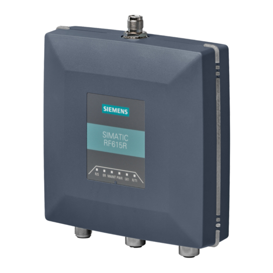
Page 124: Simatic Rf615R
: X80 DC24V (M12, 8-pin) ⑤ DI/DQ interface: X10 DI/DQ (M12, 5-pin) ⑥ Ethernet interface, TCP/IP: X1 P1 (M12, 4-pin) ) Connection of the readers to the ASM 456 communications module via the RS-422 interface. SIMATIC RF600 System Manual, 06/2019, J31069-D0171-U001-A22-7618... -
Page 125: Ordering Data
24 V connecting cable reader ↔ wide-range power supply unit 6GT2891-0PH50 with plug, 5 m • 6GT2891-4EH20 with open ends, 2 m • 6GT2891-4EH50 with open ends, 5 m • DVD "Ident Systems Software & Documentation" 6GT2080-2AA20 SIMATIC RF600 System Manual, 06/2019, J31069-D0171-U001-A22-7618... -
Page 126: Pin Assignment Of The Di/Dq Interface (X10 Di/Dq)
Output (DQ) ● The output at < 20 °C is rated for 0.5 A current (0.33 A at 55 °C) and electronically protected. ● The output is electrically isolated via optocoupler. SIMATIC RF600 System Manual, 06/2019, J31069-D0171-U001-A22-7618... -
Page 127: Simatic Rf600
Note that changes on the DI/DQ interface that are not applied for at least 1.5 seconds are not detected by the reader. Voltage infeed from external source Figure 5-7 Circuit example 1: Digital input Voltage infeed from external source Figure 5-8 Circuit example 2: Digital output SIMATIC RF600 System Manual, 06/2019, J31069-D0171-U001-A22-7618... -
Page 128: Pin Assignment Of The Power Supply Interface (X80 24Vdc)
Spécification des sources de tension externes L'alimentation du plot de lecture/écriture doit être exclusivement assurée par des blocs d'alimentation conformes aux spécifications des sources à puissance limitée (Limited Power Sources LPS) et de NEC class 2. SIMATIC RF600 System Manual, 06/2019, J31069-D0171-U001-A22-7618... -
Page 129: Pin Assignment Of The Industrial Ethernet Interface (X1 P1)
View of interface Pin assignment (M12 socket, 4-pin) Data line +Tx Data line +Rx Data line -Tx Data line -Rx 5.3.1.7 Ground connection Due to the potential-free design of the reader, no earthing measures are required. SIMATIC RF600 System Manual, 06/2019, J31069-D0171-U001-A22-7618... -
Page 130: Planning Operation
Dense Reader Mode (DRM) is used. Note Protective cap If you only use the internal antenna of the reader, we recommend that you close the external, unused antenna connector on the reader using a protective cap. SIMATIC RF600 System Manual, 06/2019, J31069-D0171-U001-A22-7618... -
Page 131: Simatic Rf600
(azimuth section) as well as the vertical plane (elevation section) must be considered. This results in a spatial image of the directional radiation pattern of the antenna. Figure 5-9 Reference system SIMATIC RF600 System Manual, 06/2019, J31069-D0171-U001-A22-7618... -
Page 132: Simatic Rf600
5.3 SIMATIC RF615R Radiation diagram (ETSI) Pattern of the vertical plane of the antenna Pattern of the horizontal plane of the antenna Figure 5-10 Directional radiation pattern of RF615R in the ETSI frequency band SIMATIC RF600 System Manual, 06/2019, J31069-D0171-U001-A22-7618... -
Page 133: Simatic Rf600
(azimuth section) as well as the vertical plane (elevation section) must be considered. This results in a spatial image of the directional radiation pattern of the antenna. Figure 5-11 Reference system SIMATIC RF600 System Manual, 06/2019, J31069-D0171-U001-A22-7618... -
Page 134: Simatic Rf600
5.3 SIMATIC RF615R Radiation diagram (FCC) Pattern of the vertical plane of the antenna Pattern of the horizontal plane of the antenna Figure 5-12 Directional radiation pattern of RF615R in the FCC frequency band SIMATIC RF600 System Manual, 06/2019, J31069-D0171-U001-A22-7618... -
Page 135: External Antenna
Examples of possible antenna reading point configurations ● A data source with an external antenna for a reading point. ● As an alternative, a data source with an internal antenna for a reading point. SIMATIC RF600 System Manual, 06/2019, J31069-D0171-U001-A22-7618... -
Page 136: Installing/Mounting
● directly on a flat surface using the VESA 100 mounting system (torque ≃ 1.5 Nm). The positions of the mounting holes for the device are shown in the section Dimension drawing (Page 141). SIMATIC RF600 System Manual, 06/2019, J31069-D0171-U001-A22-7618... -
Page 137: Configuration/Integration
Note that configuration in parallel is not possible using different tools. Simple process controls (e.g. a traffic signal) can be implemented directly using the reader via the digital input/output. Figure 5-13 Overview: Configuration of RF615R readers SIMATIC RF600 System Manual, 06/2019, J31069-D0171-U001-A22-7618... -
Page 138: Technical Specifications
≤ ±10 ppm Channel spacing ETSI 600 kHz • • 500 kHz • • CMIIT 250 kHz • • Modulation methods ASK: DSB modulation & PR-ASK modulation encoding, Manchester or Pulse Interval (PIE) Multitag capability SIMATIC RF600 System Manual, 06/2019, J31069-D0171-U001-A22-7618... -
Page 139: Simatic Rf600
• Interfaces Antenna connectors 1x RP-TNC Power supply 1x M12 (8-pin) DI/DQ interface 1x M12 (5-pin) Digital inputs Digital outputs Ethernet interface 1x M12 (4-pin), 100 Mbps Mechanical specifications Material Pocan (silicone-free) Color TI-Grey SIMATIC RF600 System Manual, 06/2019, J31069-D0171-U001-A22-7618... -
Page 140: Simatic Rf600
20 V. The values for shock and vibration are maximum values and must not be applied continuously. These values only apply to mounting using screws. SIMATIC RF600 System Manual, 06/2019, J31069-D0171-U001-A22-7618... -
Page 141: Dimension Drawing
Readers 5.3 SIMATIC RF615R 5.3.6 Dimension drawing Figure 5-14 Dimension drawing RF615R All dimensions in mm (± 0.5 mm tolerance) SIMATIC RF600 System Manual, 06/2019, J31069-D0171-U001-A22-7618... -
Page 142: Certificates And Approvals
CAN/CSA C22.2 No. 62368-1-14, 2nd Ed Audio/video, information and communication technology equipment - Part 1: Safety requirements Table 5- 22 6GT2811-6CC10-2AA0 Standard CMIIT Certification China radio approval Marking on the reader: CMIIT ID: 2019DJ2356 SIMATIC RF600 System Manual, 06/2019, J31069-D0171-U001-A22-7618... -
Page 143: Fcc Information
Readers 5.3 SIMATIC RF615R 5.3.7.3 FCC information Siemens SIMATIC RF615R (FCC): 6GT2811-6CC10-1AA0 FCC ID: NXW-RF615R This device complies with part 15 of the FCC rules. Operation is subject to the following two conditions: (1) This device may not cause harmful interference, and (2) this device must accept any interference received, including interference that may cause undesired operation. -
Page 144: Ic-Fcb Information
Readers 5.3 SIMATIC RF615R 5.3.7.4 IC-FCB information Siemens SIMATIC RF615R (FCC): 6GT2811-6CC10-1AA0 IC: 267X-RF615R This device complies with Industry Canada licence-exempt RSS standard(s). Operation is subject to the following two conditions: (1) This device may not cause interference, and (2) this device must accept any interference, including interference that may cause undesired operation of the device. -
Page 145: Simatic Rf650R
4 external antennas ② LED operating display ③ DI/DQ interface: X10 DI/DQ (M12, 12-pin) ④ Interface to power supply (RS422), 24 V : X80 DC24V (M12, 8-pin) ⑤ Ethernet interface, TCP/IP: X1 P1 (RJ45, 8-pin) SIMATIC RF600 System Manual, 06/2019, J31069-D0171-U001-A22-7618... -
Page 146: Ordering Data
M12-180 / M12-180 6GT2891-4FH50 10 m 6GT2891-4FN10 20 m 6GT2891-4FN20 50 m 6GT2891-4FN50 Wide-range power supply unit for SIMATIC RF systems 6GT2898-0AC00 With EU plug • 6GT2898-0AC10 With UK plug • 6GT2898-0AC20 With US plug • SIMATIC RF600 System Manual, 06/2019, J31069-D0171-U001-A22-7618... -
Page 147: Pin Assignment Of The Di/Dq Interface (X10 Di/Dq)
Note Requirement for external power sources When the DI/DQ interface is supplied with power by an external power source, this source must meet the requirements for LPS (Limited Power Sources) and NEC Class 2. SIMATIC RF600 System Manual, 06/2019, J31069-D0171-U001-A22-7618... -
Page 148: Switching Scheme For The Di/Dq Interface
5.4 SIMATIC RF650R Color scheme of the DI/DQ standard cable with M12 connector The following figure shows the color scheme of the DI/DQ standard cable from Siemens (6GT2891-0CH50). You can use the color scheme to assign the wire colors to the pins. -
Page 149: Simatic Rf600
Voltage infeed from internal source (no electrical isolation) Figure 5-16 Circuit example 1: Digital inputs Alternative connection possibilities: ● Pin 2 (VCC) to Pin 9 DI Common ● Pin 1 GND to busbar inputs SIMATIC RF600 System Manual, 06/2019, J31069-D0171-U001-A22-7618... -
Page 150: Simatic Rf600
Readers 5.4 SIMATIC RF650R Voltage infeed from external source Figure 5-17 Circuit example 2: Digital inputs Voltage infeed from external source with various voltages Figure 5-18 Circuit example 3: Digital inputs SIMATIC RF600 System Manual, 06/2019, J31069-D0171-U001-A22-7618... -
Page 151: Simatic Rf600
5.4 SIMATIC RF650R Voltage infeed from internal source Figure 5-19 Circuit example 4: Digital outputs Alternative connection possibilities: ● Pin 1 GND to Pin 3 DO Common ● Pin 2 (VCC) to busbar outputs SIMATIC RF600 System Manual, 06/2019, J31069-D0171-U001-A22-7618... -
Page 152: Simatic Rf600
5.4 SIMATIC RF650R Voltage infeed from external source Figure 5-20 Circuit example 5: Digital outputs Voltage infeed from an external source is shown here for 12 V as an example. Other voltages are also permissible. SIMATIC RF600 System Manual, 06/2019, J31069-D0171-U001-A22-7618... -
Page 153: Pin Assignment Of The Power Supply Interface (X80 24Vdc)
(M12 socket, 8-pin) White + 24 V Brown - Tx Green Yellow + Tx Gray + Rx Pink - Rx Unassigned Earth (shield) These pins are not required if the reader is operated via Ethernet. SIMATIC RF600 System Manual, 06/2019, J31069-D0171-U001-A22-7618... -
Page 154: Simatic Rf600
This results in a voltage drop of 0.8 volts on the 24 V cable for every 10 meters of connecting cable and with a power requirement of 500 mA. If the power requirement increases through the use of the digital inputs/outputs, the voltage drop increases accordingly. SIMATIC RF600 System Manual, 06/2019, J31069-D0171-U001-A22-7618... -
Page 155: Pin Assignment Of The Industrial Ethernet Interface (X1 P1)
Note Use of Siemens cables We recommend that you only use original Siemens cables and connectors (refer to the section "Ordering data (Page 146)") to connect to the Ethernet socket of the reader. If plug-in connectors from other manufacturers are used, it may be difficult or even impossible to remove the plug from the reader. -
Page 156: Planning Operation
● Four data sources each with one antenna for four different reading points. ● Two data sources each with two antennas for small portals. ● One data source with 4 antennas for large portals. You will find further information in the online help of the products. SIMATIC RF600 System Manual, 06/2019, J31069-D0171-U001-A22-7618... -
Page 157: Installation/Mounting
● directly on a flat surface using the VESA 100 mounting system (torque ≃ 1.5 Nm). The positions of the mounting holes for the device are shown in the section Dimension drawing (Page 165). SIMATIC RF600 System Manual, 06/2019, J31069-D0171-U001-A22-7618... -
Page 158: Simatic Rf600
1. Place the spring in the groove. 2. Mount the holder using the supplied Torx screws. When mounting the holder, make sure that the angled tip is positioned above the spring in the groove. SIMATIC RF600 System Manual, 06/2019, J31069-D0171-U001-A22-7618... -
Page 159: Simatic Rf600
3. Fit the lower part of the locking mechanism of the reader into the DIN rail. To be able to mount the reader on or remove it from the DIN rail, pull down the holder mounted in step 2. SIMATIC RF600 System Manual, 06/2019, J31069-D0171-U001-A22-7618... -
Page 160: Simatic Rf600
1. Mount the two adapter pieces using the supplied Torx screws. 2. Fit the upper part of the locking mechanism of the reader into the standard rail. 3. Secure the reader using the supplied slotted-head screws. SIMATIC RF600 System Manual, 06/2019, J31069-D0171-U001-A22-7618... -
Page 161: Configuration/Integration
Note that configuration in parallel is not possible using different tools. Simple process controls (e.g. a traffic signal) can be implemented directly using the reader via four digital inputs/outputs. Figure 5-22 Overview: Configuration of RF650R readers SIMATIC RF600 System Manual, 06/2019, J31069-D0171-U001-A22-7618... -
Page 162: Technical Specifications
≤ 8 m • • ≤ 8 m • • CMIIT ≤ 8 m • • ARIB (STD-T107) ≤ 4 m • • Protocol ISO 18000-62/-63 Transmission speed ≤ 300 kbps Frequency accuracy ≤ ±10 ppm SIMATIC RF600 System Manual, 06/2019, J31069-D0171-U001-A22-7618... -
Page 163: Simatic Rf600
30 V input voltage on the reader 410 mA / 12.3 W • • Interfaces Antenna connectors 4x RP-TNC Power supply 1x M12 (8-pin) DI/DQ interface 1x M12 (12-pin) Digital inputs Digital outputs Ethernet interface 1x RJ45 (8-pin), 100 Mbps SIMATIC RF600 System Manual, 06/2019, J31069-D0171-U001-A22-7618... -
Page 164: Simatic Rf600
20 V. The values for shock and vibration are maximum values and must not be applied continuously. These values only apply to mounting using screws. SIMATIC RF600 System Manual, 06/2019, J31069-D0171-U001-A22-7618... -
Page 165: Dimension Drawing
Readers 5.4 SIMATIC RF650R 5.4.6 Dimension drawing Figure 5-23 Dimension drawing RF650R All dimensions in mm (± 0.5 mm tolerance) SIMATIC RF600 System Manual, 06/2019, J31069-D0171-U001-A22-7618... -
Page 166: Certificates And Approvals
It meets the following safety standard(s): UL 60950-1 - Information Technology Equipment Safety - Part 1: General Requirements CSA C22.2 No. 60950 -1 - Safety of Information Technology Equip- ment UL Report E 115352 SIMATIC RF600 System Manual, 06/2019, J31069-D0171-U001-A22-7618... -
Page 167: Simatic Rf600
Argentina radio approval: Registro de la COMISION NACIONAL DE COMUNICACIONES RCPSISI14-1926 Mexico radio approval: CERTIFICADO DE HOMOLOGACION, IFETEL Australia radio approval: This product meets the requirements of the AS/NZS 3548 Norm. Table 5- 33 6GT2811-6AB20-2AA0 Standard SIMATIC RF600 System Manual, 06/2019, J31069-D0171-U001-A22-7618... -
Page 168: Fcc Information
China radio approval Marking on the reader: CMIIT ID: 2014DJ3987 5.4.7.1 FCC information Siemens SIMATIC RF650R (FCC): 6GT2811-6AB20-1AA0 FCC ID: NXW-RF600R2 This device complies with part 15 of the FCC rules. Operation is subject to the following two conditions: (1) This device may not cause harmful interference, and (2) this device must accept any interference received, including interference that may cause undesired operation. -
Page 169: Ic-Fcb Information
Readers 5.4 SIMATIC RF650R 5.4.7.2 IC-FCB information Siemens SIMATIC RF650R (FCC): 6GT2811-6AB20-1AA0 IC: 267X-RF600R2 This device complies with Industry Canada licence-exempt RSS standard(s). Operation is subject to the following two conditions: (1) This device may not cause interference, and (2) this device must accept any interference, including interference that may cause undesired operation of the device. -
Page 170: Simatic Rf680R
: X80 DC24V (M12, 8-pin) ⑥ Ethernet interface, TCP/IP: X1 P1 (M12, 4-pin) ⑦ Ethernet interface, TCP/IP: X1 P2 (M12, 4-pin) ) Connection of the readers to the ASM 456 communications module via the RS-422 interface. SIMATIC RF600 System Manual, 06/2019, J31069-D0171-U001-A22-7618... -
Page 171: Ordering Data
6XV1871-5TH30 6XV1871-5TH50 6XV1840-2AH10 Industrial Ethernet cable • by the meter, green (minimum 20 m) 6GT2891-4FH20 Connecting cable reader ↔ CM • M12-180 / M12-180 6GT2891-4FH50 10 m 6GT2891-4FN10 20 m 6GT2891-4FN20 50 m 6GT2891-4FN50 SIMATIC RF600 System Manual, 06/2019, J31069-D0171-U001-A22-7618... -
Page 172: Pin Assignment Of The Di/Dq Interface (X10 Di/Dq)
DO 2 / Output 02 DO 3 / Output 03 DI 0 / Input 00 DI Common / Input Common DI 1 / Input 01 DI 2 / Input 02 DI 3 / Input 03 SIMATIC RF600 System Manual, 06/2019, J31069-D0171-U001-A22-7618... -
Page 173: Switching Scheme For The Di/Dq Interface
LPS (Limited Power Sources) and NEC Class 2. Color scheme of the DI/DQ standard cable with M12 connector The following figure shows the color scheme of the DI/DQ standard cable from Siemens (6GT2891-0CH50). You can use the color scheme to assign the wire colors to the pins. -
Page 174: Simatic Rf600
Voltage infeed from internal source (no electrical isolation) Figure 5-25 Circuit example 1: Digital inputs Alternative connection possibilities: ● Pin 2 (VCC) to Pin 9 DI Common ● Pin 1 GND to busbar inputs SIMATIC RF600 System Manual, 06/2019, J31069-D0171-U001-A22-7618... -
Page 175: Simatic Rf600
Readers 5.5 SIMATIC RF680R Voltage infeed from external source Figure 5-26 Circuit example 2: Digital inputs Voltage infeed from external source with various voltages Figure 5-27 Circuit example 3: Digital inputs SIMATIC RF600 System Manual, 06/2019, J31069-D0171-U001-A22-7618... -
Page 176: Simatic Rf600
5.5 SIMATIC RF680R Voltage infeed from internal source Figure 5-28 Circuit example 4: Digital outputs Alternative connection possibilities: ● Pin 1 GND to Pin 3 DO Common ● Pin 2 (VCC) to busbar outputs SIMATIC RF600 System Manual, 06/2019, J31069-D0171-U001-A22-7618... -
Page 177: Simatic Rf600
5.5 SIMATIC RF680R Voltage infeed from external source Figure 5-29 Circuit example 5: Digital outputs Voltage infeed from an external source is shown here for 12 V as an example. Other voltages are also permissible. SIMATIC RF600 System Manual, 06/2019, J31069-D0171-U001-A22-7618... -
Page 178: Pin Assignment Of The Power Supply Interface (X80 24Vdc)
(M12 socket, 8-pin) White + 24 V Brown - Tx Green Yellow + Tx Gray + Rx Pink - Rx Unassigned Earth (shield) These pins are not required if the reader is operated via Ethernet. SIMATIC RF600 System Manual, 06/2019, J31069-D0171-U001-A22-7618... -
Page 179: Simatic Rf600
This results in a voltage drop of 0.8 volts on the 24 V cable for every 10 meters of connecting cable and with a power requirement of 500 mA. If the power requirement increases through the use of the digital inputs/outputs, the voltage drop increases accordingly. SIMATIC RF600 System Manual, 06/2019, J31069-D0171-U001-A22-7618... -
Page 180: Pin Assignment Of The Industrial Ethernet Interface (X1 P1; X1 P2)
Installation only in protected areas The antenna can be installed in the protected part of a building. When implementing your lightning protection concept, make sure you adhere to the VDE 0182 or IEC 62305 standards. SIMATIC RF600 System Manual, 06/2019, J31069-D0171-U001-A22-7618... -
Page 181: Planning Operation
● Four data sources each with one antenna for four different reading points. ● Two data sources each with two antennas for small portals. ● One data source with 4 antennas for large portals. You will find further information in the online help of the products. SIMATIC RF600 System Manual, 06/2019, J31069-D0171-U001-A22-7618... -
Page 182: Installation/Mounting
HF radiation, provided that a minimum spacing of 26 cm exists between antenna and person. When the antennas are installed, you must therefore ensure that a minimum spacing of 26 cm is maintained between personnel and antennas. SIMATIC RF600 System Manual, 06/2019, J31069-D0171-U001-A22-7618... -
Page 183: Mounting/Installation
The positions of the mounting holes for the device are shown in the section Dimension drawing (Page 190). Mounting the reader on a DIN/standard rail Table 5- 39 DIN rail mounting Description 1. Place the spring in the groove. SIMATIC RF600 System Manual, 06/2019, J31069-D0171-U001-A22-7618... -
Page 184: Simatic Rf600
3. Fit the lower part of the locking mechanism of the reader into the DIN rail. To be able to mount the reader on or remove it from the DIN rail, pull down the holder mounted in step 2. SIMATIC RF600 System Manual, 06/2019, J31069-D0171-U001-A22-7618... -
Page 185: Simatic Rf600
1. Mount the two adapter pieces using the supplied Torx screws. 2. Fit the upper part of the locking mechanism of the reader into the standard rail. 3. Secure the reader using the supplied slotted-head screws. SIMATIC RF600 System Manual, 06/2019, J31069-D0171-U001-A22-7618... -
Page 186: Configuration/Integration
Note that configuration in parallel is not possible using different tools. Simple process controls (e.g. a traffic signal) can be implemented directly using the reader via four digital inputs/outputs. Figure 5-31 Overview: Configuration of RF680R readers SIMATIC RF600 System Manual, 06/2019, J31069-D0171-U001-A22-7618... -
Page 187: Technical Specifications
≤ 8 m • • ≤ 8 m • • CMIIT ≤ 8 m • • ARIB (STD-T106) ≤ 8 m • • Protocol ISO 18000-62/-63 Transmission speed ≤ 300 kbps Frequency accuracy ≤ ±10 ppm SIMATIC RF600 System Manual, 06/2019, J31069-D0171-U001-A22-7618... -
Page 188: Simatic Rf600
30 V input voltage on the reader 410 mA / 12.3 W • • Interfaces Antenna connectors 4x RP-TNC Power supply 1x M12 (8-pin) DI/DQ interface 1x M12 (12-pin) Digital inputs Digital outputs Ethernet interface 2x M12 (4-pin), 100 Mbps SIMATIC RF600 System Manual, 06/2019, J31069-D0171-U001-A22-7618... -
Page 189: Simatic Rf600
258 × 258 × 80 mm Weight 2.4 kg Type of mounting Mounting rail Hanging • • VESA 100 4x M4 screws (≃ 1.5 Nm) • • Operation indicator 8 LEDs Status display 9 LEDs SIMATIC RF600 System Manual, 06/2019, J31069-D0171-U001-A22-7618... -
Page 190: Dimension Drawing
The values for shock and vibration are maximum values and must not be applied continuously. These values only apply to mounting using screws. 5.5.6 Dimension drawing Figure 5-32 Dimension drawing RF680R All dimensions in mm (± 0.5 mm tolerance) SIMATIC RF600 System Manual, 06/2019, J31069-D0171-U001-A22-7618... -
Page 191: Certificates And Approvals
It meets the following safety standard(s): UL 60950-1 - Information Technology Equipment Safety - Part 1: General Requirements CSA C22.2 No. 60950 -1 - Safety of Information Technology Equip- ment UL Report E 115352 SIMATIC RF600 System Manual, 06/2019, J31069-D0171-U001-A22-7618... -
Page 192: Simatic Rf600
CERTIFICADO DE HOMOLOGACION, IFETEL Australia radio approval: This product meets the requirements of the AS/NZS 3548 Norm. Table 5- 44 6GT2811-6AA10-2AA0 Standard CMIIT Certification China radio approval Marking on the reader: CMIIT ID: 2014DJ3988 SIMATIC RF600 System Manual, 06/2019, J31069-D0171-U001-A22-7618... -
Page 193: Fcc Information
Readers 5.5 SIMATIC RF680R 5.5.7.1 FCC information Siemens SIMATIC RF680R (FCC): 6GT2811-6AA10-1AA0 FCC ID: NXW-RF600R2 This device complies with part 15 of the FCC rules. Operation is subject to the following two conditions: (1) This device may not cause harmful interference, and (2) this device must accept any interference received, including interference that may cause undesired operation. -
Page 194: Ic-Fcb Information
Readers 5.5 SIMATIC RF680R 5.5.7.2 IC-FCB information Siemens SIMATIC RF680R (FCC): 6GT2811-6AA10-1AA0 IC: 267X-RF600R2 This device complies with Industry Canada licence-exempt RSS standard(s). Operation is subject to the following two conditions: (1) This device may not cause interference, and (2) this device must accept any interference, including interference that may cause undesired operation of the device. -
Page 195: Simatic Rf685R
: X80 DC24V (M12, 8-pin) ⑥ Ethernet interface, TCP/IP: X1 P1 (M12, 4-pin) ⑦ Ethernet interface, TCP/IP: X1 P2 (M12, 4-pin) ) Connection of the readers to the ASM 456 communications module via the RS-422 interface. SIMATIC RF600 System Manual, 06/2019, J31069-D0171-U001-A22-7618... -
Page 196: Ordering Data
6XV1871-5TH30 6XV1871-5TH50 6XV1840-2AH10 Industrial Ethernet cable • by the meter, green (minimum 20 m) 6GT2891-4FH20 Connecting cable reader ↔ CM • M12-180 / M12-180 6GT2891-4FH50 10 m 6GT2891-4FN10 20 m 6GT2891-4FN20 50 m 6GT2891-4FN50 SIMATIC RF600 System Manual, 06/2019, J31069-D0171-U001-A22-7618... -
Page 197: Pin Assignment Of The Di/Dq Interface (X10 Di/Dq)
DO 2 / Output 02 DO 3 / Output 03 DI 0 / Input 00 DI Common / Input Common DI 1 / Input 01 DI 2 / Input 02 DI 3 / Input 03 SIMATIC RF600 System Manual, 06/2019, J31069-D0171-U001-A22-7618... -
Page 198: Switching Scheme For The Di/Dq Interface
LPS (Limited Power Sources) and NEC Class 2. Color scheme of the DI/DQ standard cable with M12 connector The following figure shows the color scheme of the DI/DQ standard cable from Siemens (6GT2891-0CH50). You can use the color scheme to assign the wire colors to the pins. -
Page 199: Simatic Rf600
Voltage infeed from internal source (no electrical isolation) Figure 5-34 Circuit example 1: Digital inputs Alternative connection possibilities: ● Pin 2 (VCC) to Pin 9 DI Common ● Pin 1 GND to busbar inputs SIMATIC RF600 System Manual, 06/2019, J31069-D0171-U001-A22-7618... -
Page 200: Simatic Rf600
Readers 5.6 SIMATIC RF685R Voltage infeed from external source Figure 5-35 Circuit example 2: Digital inputs Voltage infeed from external source with various voltages Figure 5-36 Circuit example 3: Digital inputs SIMATIC RF600 System Manual, 06/2019, J31069-D0171-U001-A22-7618... -
Page 201: Simatic Rf600
5.6 SIMATIC RF685R Voltage infeed from internal source Figure 5-37 Circuit example 4: Digital outputs Alternative connection possibilities: ● Pin 1 GND to Pin 3 DO Common ● Pin 2 (VCC) to busbar outputs SIMATIC RF600 System Manual, 06/2019, J31069-D0171-U001-A22-7618... -
Page 202: Simatic Rf600
5.6 SIMATIC RF685R Voltage infeed from external source Figure 5-38 Circuit example 5: Digital outputs Voltage infeed from an external source is shown here for 12 V as an example. Other voltages are also permissible. SIMATIC RF600 System Manual, 06/2019, J31069-D0171-U001-A22-7618... -
Page 203: Pin Assignment Of The Power Supply Interface (X80 24Vdc)
(M12 socket, 8-pin) White + 24 V Brown - Tx Green Yellow + Tx Gray + Rx Pink - Rx Unassigned Earth (shield) These pins are not required if the reader is operated via Ethernet. SIMATIC RF600 System Manual, 06/2019, J31069-D0171-U001-A22-7618... -
Page 204: Simatic Rf600
This results in a voltage drop of 0.8 volts on the 24 V cable for every 10 meters of connecting cable and with a power requirement of 500 mA. If the power requirement increases through the use of the digital inputs/outputs, the voltage drop increases accordingly. SIMATIC RF600 System Manual, 06/2019, J31069-D0171-U001-A22-7618... -
Page 205: Pin Assignment Of The Industrial Ethernet Interface (X1 P1; X1 P2)
Installation only in protected areas The antenna can be installed in the protected part of a building. When implementing your lightning protection concept, make sure you adhere to the VDE 0182 or IEC 62305 standards. SIMATIC RF600 System Manual, 06/2019, J31069-D0171-U001-A22-7618... -
Page 206: Planning Operation
Dense Reader Mode (DRM) is used. Note Protective cap If you only use the internal antenna of the reader, we recommend that you close the external, unused antenna connector on the reader using a protective cap. SIMATIC RF600 System Manual, 06/2019, J31069-D0171-U001-A22-7618... -
Page 207: Simatic Rf600
(azimuth section) as well as the vertical plane (elevation section) must be considered. This results in a spatial image of the directional radiation pattern of the antenna. Figure 5-40 Reference system SIMATIC RF600 System Manual, 06/2019, J31069-D0171-U001-A22-7618... -
Page 208: Simatic Rf600
Readers 5.6 SIMATIC RF685R Radiation diagram (Azimuth section) Figure 5-41 Azimuth section SIMATIC RF600 System Manual, 06/2019, J31069-D0171-U001-A22-7618... -
Page 209: Simatic Rf600
Readers 5.6 SIMATIC RF685R Radiation diagram (elevation section) Figure 5-42 Elevation section SIMATIC RF600 System Manual, 06/2019, J31069-D0171-U001-A22-7618... -
Page 210: Simatic Rf600
5 dBi in the frequency band 865 to 868 MHz Antenna axis ratio 2 dB You will find more information on the antennas in the section "Guidelines for selecting RFID UHF antennas (Page 51)". SIMATIC RF600 System Manual, 06/2019, J31069-D0171-U001-A22-7618... -
Page 211: Simatic Rf600
(azimuth section) as well as the vertical plane (elevation section) must be considered. This results in a spatial image of the directional radiation pattern of the antenna. Figure 5-44 Reference system SIMATIC RF600 System Manual, 06/2019, J31069-D0171-U001-A22-7618... -
Page 212: Simatic Rf600
Readers 5.6 SIMATIC RF685R Radiation diagram (Azimuth section) Figure 5-45 Azimuth section SIMATIC RF600 System Manual, 06/2019, J31069-D0171-U001-A22-7618... -
Page 213: Simatic Rf600
Readers 5.6 SIMATIC RF685R Radiation diagram (elevation section) Figure 5-46 Elevation section SIMATIC RF600 System Manual, 06/2019, J31069-D0171-U001-A22-7618... -
Page 214: Simatic Rf600
5 dBi in the frequency band 902 to 928 MHz Antenna axis ratio 2 dB You will find more information on the antennas in the section "Guidelines for selecting RFID UHF antennas (Page 51)". SIMATIC RF600 System Manual, 06/2019, J31069-D0171-U001-A22-7618... -
Page 215: External Antenna
Examples of possible antenna reading point configurations ● A data source with an external antenna for a reading point. ● As an alternative, a data source with an internal antenna for a reading point. SIMATIC RF600 System Manual, 06/2019, J31069-D0171-U001-A22-7618... -
Page 216: Installation/Mounting
● directly on a flat surface using the VESA 100 mounting system (torque ≃ 1.5 Nm). The positions of the mounting holes for the device are shown in the section Dimension drawing (Page 224). SIMATIC RF600 System Manual, 06/2019, J31069-D0171-U001-A22-7618... -
Page 217: Simatic Rf600
1. Place the spring in the groove. 2. Mount the holder using the supplied Torx screws. When mounting the holder, make sure that the angled tip is positioned above the spring in the groove. SIMATIC RF600 System Manual, 06/2019, J31069-D0171-U001-A22-7618... -
Page 218: Simatic Rf600
3. Fit the lower part of the locking mechanism of the reader into the DIN rail. To be able to mount the reader on or remove it from the DIN rail, pull down the holder mounted in step 2. SIMATIC RF600 System Manual, 06/2019, J31069-D0171-U001-A22-7618... -
Page 219: Simatic Rf600
1. Mount the two adapter pieces using the supplied Torx screws. 2. Fit the upper part of the locking mechanism of the reader into the standard rail. 3. Secure the reader using the supplied slotted-head screws. SIMATIC RF600 System Manual, 06/2019, J31069-D0171-U001-A22-7618... -
Page 220: Configuration/Integration
Note that configuration in parallel is not possible using different tools. Simple process controls (e.g. a traffic signal) can be implemented directly using the reader via four digital inputs/outputs. Figure 5-48 Overview: Configuration of RF685R readers SIMATIC RF600 System Manual, 06/2019, J31069-D0171-U001-A22-7618... -
Page 221: Technical Specifications
≤ 8 m • • ≤ 8 m • • CMIIT ≤ 8 m • • ARIB (STD-T106) ≤ 8 m • • Protocol ISO 18000-62/-63 Transmission speed ≤ 300 kbps Frequency accuracy ≤ ±10 ppm SIMATIC RF600 System Manual, 06/2019, J31069-D0171-U001-A22-7618... -
Page 222: Simatic Rf600
30 V input voltage on the reader 410 mA / 12.3 W • • Interfaces Antenna connectors 1x RP-TNC Power supply 1x M12 (8-pin) DI/DQ interface 1x M12 (12-pin) Digital inputs Digital outputs Ethernet interface 2x M12 (4-pin), 100 Mbps SIMATIC RF600 System Manual, 06/2019, J31069-D0171-U001-A22-7618... -
Page 223: Simatic Rf600
258 × 258 × 80 mm Weight 2.47 kg Type of mounting Mounting rail Hanging • • VESA 100 4x M4 screws (≃ 1.5 Nm) • • Operation indicator 8 LEDs Status display 9 LEDs SIMATIC RF600 System Manual, 06/2019, J31069-D0171-U001-A22-7618... -
Page 224: Dimension Drawing
The values for shock and vibration are maximum values and must not be applied continuously. These values only apply to mounting using screws. 5.6.6 Dimension drawing Figure 5-49 Dimension drawing RF685R All dimensions in mm (± 0.5 mm tolerance) SIMATIC RF600 System Manual, 06/2019, J31069-D0171-U001-A22-7618... -
Page 225: Certificates And Approvals
It meets the following safety standard(s): UL 60950-1 - Information Technology Equipment Safety - Part 1: General Requirements CSA C22.2 No. 60950 -1 - Safety of Information Technology Equip- ment UL Report E 115352 SIMATIC RF600 System Manual, 06/2019, J31069-D0171-U001-A22-7618... -
Page 226: Simatic Rf600
CERTIFICADO DE HOMOLOGACION, IFETEL Australia radio approval: This product meets the requirements of the AS/NZS 3548 Norm. Table 5- 58 6GT2811-6CA10-2AA0 Standard CMIIT Certification China radio approval Marking on the reader: CMIIT ID: 2014DJ3989 SIMATIC RF600 System Manual, 06/2019, J31069-D0171-U001-A22-7618... -
Page 227: Fcc Information
Readers 5.6 SIMATIC RF685R 5.6.7.1 FCC information Siemens SIMATIC RF685R (FCC): 6GT2811-6CA10-1AA0 FCC ID: NXW-RF600R2 This device complies with part 15 of the FCC rules. Operation is subject to the following two conditions: (1) This device may not cause harmful interference, and (2) this device must accept any interference received, including interference that may cause undesired operation. -
Page 228: Ic-Fcb Information
Readers 5.6 SIMATIC RF685R 5.6.7.2 IC-FCB information Siemens SIMATIC RF685R (FCC): 6GT2811-6CA10-1AA0 IC: 267X-RF600R2 This device complies with Industry Canada licence-exempt RSS standard(s). Operation is subject to the following two conditions: (1) This device may not cause interference, and (2) this device must accept any interference, including interference that may cause undesired operation of the device. -
Page 229: Simatic Rf650M
● API software interface The SIMATIC RF650M Mobile handheld terminal is supplied with an API software interface that can be used by customized user programs. You can perform the following functions with the SIMATIC RF650M handheld terminal: SIMATIC RF600 System Manual, 06/2019, J31069-D0171-U001-A22-7618... -
Page 230: Simatic Rf600
● Easy creation of your own RFID applications with the software "Application Interface" (API) You will find further information on the RF650M handheld terminal in the operating instructions "SIMATIC RF650M mobile handheld terminal (https://support.industry.siemens.com/cs/ww/en/view/109475735)". SIMATIC RF600 System Manual, 06/2019, J31069-D0171-U001-A22-7618... -
Page 231: Antennas
(IP rating is not investigated by UL) Permissible -20 °C ... +70 °C -25 °C ... +75 °C ambient temperature Lowest values apply when mounted on non-metallic surfaces; the higher values apply when mounted on metallic sur- faces. SIMATIC RF600 System Manual, 06/2019, J31069-D0171-U001-A22-7618... -
Page 232: Simatic Rf600
Vertic. plane: 70° Vertic. plane: 76° Vertic. plane: 80° Vertic. plane: 77° Connector RP-TNC coupling Mounting type 4x screws M4 (VESA 100 fastening system) Degree of protection IP65 Permissible -25 °C ... +75 °C ambient temperature SIMATIC RF600 System Manual, 06/2019, J31069-D0171-U001-A22-7618... -
Page 233: Simatic Rf615A
● RF615A FCC: 902 to 928 MHz Function The SIMATIC RF615A is used for transmitting and receiving data in the UHF range. The antennas are connected to the SIMATIC RF600 readers via antenna cables that are available in different lengths. SIMATIC RF600... -
Page 234: Ordering Data
Note that the antenna gain depends on the material of the mounting surface. If the antenna is mounted on a metallic surface, the antenna gain is -5 dBi. If the antenna is mounted on a non-metallic surface, the antenna gain is -13 dBi. SIMATIC RF600 System Manual, 06/2019, J31069-D0171-U001-A22-7618... -
Page 235: Connecting The Antenna
Requirement Note Use of Siemens antenna cable To ensure optimum functioning of the antenna, it is recommended that a Siemens antenna cable is used in accordance with the list of accessories. Strain relief To protect the antenna connecting cable from strain, you can attach strain relief, e.g. in the form of a strain relief clamp. -
Page 236: Antenna Parameter Assignment
● Antenna gain: -5 dBi ● Radiated power: ≤ 340 mW ERP (or 25.35 dBm ERP) Converted into EIRP: ≤ 560 mW EIRP (or 27.5 dBm EIRP) ● Use of cable loss associated with the antenna cable. SIMATIC RF600 System Manual, 06/2019, J31069-D0171-U001-A22-7618... -
Page 237: Simatic Rf600
● Radiated power: ≤ 2000 mW ERP (or 33 dBm ERP) Converted into EIRP: ≤ 3250 mW EIRP (or 35 dBm EIRP) ● Use of cable loss associated with the antenna cable. SIMATIC RF600 System Manual, 06/2019, J31069-D0171-U001-A22-7618... -
Page 238: Antenna Patterns
The polarization axes of antenna and transponder must always be parallel. The symbol on the antenna indicates the polarization axis. Figure 6-2 Polarization axis SIMATIC RF600 System Manual, 06/2019, J31069-D0171-U001-A22-7618... -
Page 239: Simatic Rf600
Antennas 6.2 SIMATIC RF615A Alignment The following diagram shows the optimum alignment of the RF600 transponders to the RF615A antenna. Figure 6-3 Optimum alignment of transponders to the antenna SIMATIC RF600 System Manual, 06/2019, J31069-D0171-U001-A22-7618... -
Page 240: Simatic Rf600
The following diagram shows the dependence of the following factors: ● Alignment angle of transponder to antenna ● Maximum range of antenna Figure 6-4 Effect on the read/write range depending on the antenna alignment SIMATIC RF600 System Manual, 06/2019, J31069-D0171-U001-A22-7618... -
Page 241: Antenna Pattern Etsi
The range (in %) corresponding to the dB values in the patterns can be obtained from this table . Note that the measurements presented graphically below were carried out in a low-reflection environment. Deviations can therefore occur in a normally reflecting environment. SIMATIC RF600 System Manual, 06/2019, J31069-D0171-U001-A22-7618... -
Page 242: Simatic Rf600
Directional radiation pattern ETSI on metallic mounting surface (15 cm x 15 cm) Pattern of the vertical plane of the antenna Pattern of the horizontal plane of the antenna Figure 6-6 Directional radiation pattern RF615A ETSI on metallic mounting surface SIMATIC RF600 System Manual, 06/2019, J31069-D0171-U001-A22-7618... -
Page 243: Simatic Rf600
Directional radiation pattern ETSI on non-metallic mounting surface Pattern of the vertical plane of the antenna Pattern of the horizontal plane of the antenna Figure 6-7 Directional radiation pattern RF615A ETSI on non-metallic mounting surface SIMATIC RF600 System Manual, 06/2019, J31069-D0171-U001-A22-7618... -
Page 244: Antenna Pattern Fcc
%) corresponds to the dB values in the patterns can be obtained from this table . Note that the measurements presented graphically below were carried out in a low-reflection environment. Low deviations can therefore occur in a normally reflecting environment. SIMATIC RF600 System Manual, 06/2019, J31069-D0171-U001-A22-7618... -
Page 245: Simatic Rf600
Directional radiation pattern of the RF615A (FCC) on metallic mounting surface (15 cm x 15 cm) Pattern of the vertical plane of the antenna Pattern of the horizontal plane of the antenna Figure 6-9 Directional radiation pattern of the RF615A (FCC) on metallic mounting surface SIMATIC RF600 System Manual, 06/2019, J31069-D0171-U001-A22-7618... -
Page 246: Simatic Rf600
Directional radiation pattern of the RF615A (FCC) on non-metallic mounting surface Pattern of the vertical plane of the antenna Pattern of the horizontal plane of the antenna Figure 6-10 Directional radiation pattern of the RF615A (FCC) on non-metallic mounting surface SIMATIC RF600 System Manual, 06/2019, J31069-D0171-U001-A22-7618... -
Page 247: Interpretation Of Directional Radiation Patterns
+ 50° from the Z axis within the vertical plane (see line shown in blue in the directional radiation pattern: Characteristic of the vertical plane of the antenna and the associated representation of the reference system). SIMATIC RF600 System Manual, 06/2019, J31069-D0171-U001-A22-7618... -
Page 248: Technical Data
15 cm x 15 cm ETSI Horizontal plane: 100° • • Vertical plane: 75° see section "Antenna pattern ETSI (Page 241)" Horizontal plane: 130 • • Vertical plane: 105° see section "Antenna pattern FCC (Page 244)" SIMATIC RF600 System Manual, 06/2019, J31069-D0171-U001-A22-7618... -
Page 249: Simatic Rf600
(IP rating is not investigated by UL) Shock resistant to EN 60068-2-27 50 g Vibration to EN 60068-2-6 20 g Design, dimensions and weight Dimensions (H x W x D) 52 x 52 x 16 mm Weight 60 g SIMATIC RF600 System Manual, 06/2019, J31069-D0171-U001-A22-7618... -
Page 250: Dimension Drawing
The values differ for different dimensions/materials of the mounting surface. The values for shock and vibration are maximum values and must not be applied continuously. 6.2.8 Dimension drawing Figure 6-11 Dimension drawing RF615A All dimensions in mm SIMATIC RF600 System Manual, 06/2019, J31069-D0171-U001-A22-7618... -
Page 251: Certificates & Approvals
This product is UL-certified for the USA and Canada. It meets the following safety standard(s): UL Report E115352 • UL 62368-1 - AVICT Equipment - Part 1: Safety Requirements • CSA C22.2 No. 62368-1-14 AVICT Equipment - Part 1: Saftey • Requirements SIMATIC RF600 System Manual, 06/2019, J31069-D0171-U001-A22-7618... -
Page 252: Simatic Rf620A
● RF620A FCC: 902 to 928 MHz Function The SIMATIC RF620A is used for transmitting and receiving data in the UHF range. The antennas are connected to the SIMATIC RF600 readers via antenna cables that are available in different lengths. SIMATIC RF600... -
Page 253: Ordering Data
Note that the antenna gain depends on the material of the mounting surface. If the antenna is mounted on a metallic surface, the antenna gain is -5 dBi. If the antenna is mounted on a non-metallic surface, the antenna gain is -10 dBi. SIMATIC RF600 System Manual, 06/2019, J31069-D0171-U001-A22-7618... -
Page 254: Connecting The Antenna
Requirement Note Use of Siemens antenna cable To ensure optimum functioning of the antenna, it is recommended that a Siemens antenna cable is used in accordance with the list of accessories. Strain relief To protect the antenna connecting cable from strain, you can attach strain relief, e.g. in the form of a strain relief clamp. -
Page 255: Antenna Parameter Assignment
● Antenna gain: -5 dBi ● Radiated power: ≤ 340 mW ERP (or 25.35 dBm ERP) Converted into EIRP: ≤ 560 mW EIRP (or 27.5 dBm EIRP) ● Use of cable loss associated with the antenna cable. SIMATIC RF600 System Manual, 06/2019, J31069-D0171-U001-A22-7618... -
Page 256: Simatic Rf600
● Radiated power: ≤ 2000 mW ERP (or 33 dBm ERP) Converted into EIRP: ≤ 3250 mW EIRP (or 35 dBm EIRP) ● Use of cable loss associated with the antenna cable. SIMATIC RF600 System Manual, 06/2019, J31069-D0171-U001-A22-7618... -
Page 257: Antenna Patterns
The polarization axes of antenna and transponder must always be parallel. The symbol on the antenna indicates the polarization axis. Figure 6-13 Polarization axis SIMATIC RF600 System Manual, 06/2019, J31069-D0171-U001-A22-7618... -
Page 258: Simatic Rf600
Antennas 6.3 SIMATIC RF620A Alignment The following diagram shows the optimum alignment of the RF600 transponders to the RF620A antenna. Figure 6-14 Antenna/transponder alignment SIMATIC RF600 System Manual, 06/2019, J31069-D0171-U001-A22-7618... -
Page 259: Simatic Rf600
Angle deviation diagram for alignment The following diagram shows the dependence of the following factors: ● Alignment angle of transponder to antenna ● Maximum range of antenna Figure 6-15 Angle deviation diagram for alignment SIMATIC RF600 System Manual, 06/2019, J31069-D0171-U001-A22-7618... -
Page 260: Antenna Pattern Etsi
Which range (in %) corresponds to the dB values in the patterns can be obtained from this table . Note that the measurements presented graphically below were carried out in a low-reflection environment. Deviations can therefore occur in a normally reflecting environment. SIMATIC RF600 System Manual, 06/2019, J31069-D0171-U001-A22-7618... -
Page 261: Simatic Rf600
Directional radiation pattern ETSI on metallic mounting surface (15 cm x 15 cm) Pattern of the vertical plane of the antenna Pattern of the horizontal plane of the antenna Figure 6-17 Directional radiation pattern RF620A ETSI on metallic mounting surface SIMATIC RF600 System Manual, 06/2019, J31069-D0171-U001-A22-7618... -
Page 262: Simatic Rf600
Directional radiation pattern ETSI on non-metallic mounting surface Pattern of the vertical plane of the antenna Pattern of the horizontal plane of the antenna Figure 6-18 Directional radiation pattern RF620A ETSI on non-metallic mounting surface SIMATIC RF600 System Manual, 06/2019, J31069-D0171-U001-A22-7618... -
Page 263: Antenna Pattern Fcc
%) corresponds to the dB values in the patterns can be obtained from this table . Note that the measurements presented graphically below were carried out in a low-reflection environment. Low deviations can therefore occur in a normally reflecting environment. SIMATIC RF600 System Manual, 06/2019, J31069-D0171-U001-A22-7618... -
Page 264: Simatic Rf600
Directional radiation pattern of the RF620A (FCC) on metallic mounting surface (15 cm x 15 cm) Pattern of the vertical plane of the antenna Pattern of the horizontal plane of the antenna Figure 6-20 Directional radiation pattern of the RF620A (FCC) on metallic mounting surface SIMATIC RF600 System Manual, 06/2019, J31069-D0171-U001-A22-7618... -
Page 265: Simatic Rf600
Directional radiation pattern of the RF620A (FCC) on non-metallic mounting surface Pattern of the vertical plane of the antenna Pattern of the horizontal plane of the antenna Figure 6-21 Directional radiation pattern of the RF620A (FCC) on non-metallic mounting surface SIMATIC RF600 System Manual, 06/2019, J31069-D0171-U001-A22-7618... -
Page 266: Interpretation Of Directional Radiation Patterns
± 40° from the Z axis within the vertical plane (see line shown in blue in the directional radiation pattern: Characteristic of the vertical plane of the antenna and the associated representation of the reference system). SIMATIC RF600 System Manual, 06/2019, J31069-D0171-U001-A22-7618... -
Page 267: Technical Data
Opening angle for sending/receiving when mounted on a metal surface of 15 cm x 15 cm ETSI Horizontal plane: 100° • • Vertical plane: 75° see section "Antenna pattern ETSI (Page 260)" Horizontal plane: 130 • • Vertical plane: 105° see section "Antenna pattern FCC (Page 263)" SIMATIC RF600 System Manual, 06/2019, J31069-D0171-U001-A22-7618... -
Page 268: Simatic Rf600
FCC (Title 47, Part 15.247), cULus • • MTBF 1190 years The values differ for different dimensions/materials of the mounting surface. The values for shock and vibration are maximum values and must not be applied continuously. SIMATIC RF600 System Manual, 06/2019, J31069-D0171-U001-A22-7618... -
Page 269: Dimension Drawing
Antennas 6.3 SIMATIC RF620A 6.3.8 Dimension drawing Figure 6-22 Dimension drawing RF620A All dimensions in mm SIMATIC RF600 System Manual, 06/2019, J31069-D0171-U001-A22-7618... -
Page 270: Approvals & Certificates
It meets the following safety standard(s): UL Report E205089 • UL 60950-1 - Information Technology Equipment Safety - Part 1: • General Requirements CSA C22.2 No. 60950-1 - Safety of Information Technology • Equipment SIMATIC RF600 System Manual, 06/2019, J31069-D0171-U001-A22-7618... -
Page 271: Simatic Rf640A
MHz. Function The SIMATIC RF640A is used for transmitting and receiving data in the UHF range. The antennas are connected to the SIMATIC RF600 readers via antenna cables that are available in different lengths. SIMATIC RF600 System Manual, 06/2019, J31069-D0171-U001-A22-7618... -
Page 272: Ordering Data
To achieve optimum wave propagation, the antenna should not be surrounded by conducting objects. The area between antenna and transponder should also allow wave propagation without interference. Antenna holders The Siemens antenna holders allow for fine adjustment of the antenna field by setting the solid angle. SIMATIC RF600 System Manual, 06/2019, J31069-D0171-U001-A22-7618... -
Page 273: Connecting The Antenna
Requirement Note Use of Siemens antenna cable To ensure optimum functioning of the antenna, it is recommended that a Siemens antenna cable is used in accordance with the list of accessories. Strain relief To protect the antenna connecting cable from strain, you can attach strain relief, e.g. in the form of a strain relief clamp. -
Page 274: Bending Radii And Bending Cycles Of The Cable
RF600 systems that are put into operation in the EU, EFTA or Turkey must not exceed the following radiated power with an RF640A antenna: • 2000 mW ERP (or 33 dBm ERP) Converted into EIRP: 3250 mW EIRP (or 35 dBm EIRP) SIMATIC RF600 System Manual, 06/2019, J31069-D0171-U001-A22-7618... -
Page 275: Simatic Rf600
● Antenna gain: 4.3 dBi (or 7.3 dBiC) ● Radiated power: ≤ 2000 mW ERP (or 33 dBm ERP) Converted into EIRP: ≤ 3250 mW EIRP (or 35 dBm EIRP) ● Use of cable loss associated with the antenna cable. SIMATIC RF600 System Manual, 06/2019, J31069-D0171-U001-A22-7618... -
Page 276: Setting Rf640A Parameters For Rf680R/Rf685R
● Antenna gain: 4 dBi (or 7 dBiC) ● Radiated power: ≤ 2000 mW ERP (or 33 dBm ERP) Converted into EIRP: ≤ 3250 mW EIRP (or 35 dBm EIRP) ● Use of cable loss associated with the antenna cable. SIMATIC RF600 System Manual, 06/2019, J31069-D0171-U001-A22-7618... -
Page 277: Simatic Rf600
Limitation of the radiated power (ARIB STD-T106) RF600 systems that are put into operation in Japan must not exceed the following radiated power with an RF640A antenna: • 4000 mW EIRP (or 36 dBm EIRP) SIMATIC RF600 System Manual, 06/2019, J31069-D0171-U001-A22-7618... -
Page 278: Antenna Patterns
The range (in %) corresponding to the dB values in the patterns can be obtained from this table (Page 288). Note that the measurements presented graphically below were carried out in a low-reflection environment. Deviations can therefore occur in a normally reflecting environment. SIMATIC RF600 System Manual, 06/2019, J31069-D0171-U001-A22-7618... -
Page 279: Simatic Rf600
Polarization axis and axis of symmetry are parallel In a configuration based on the following directional radiation pattern of the antenna, the axis of symmetry of the antenna and the polarization axis of the transponder are parallel. SIMATIC RF600 System Manual, 06/2019, J31069-D0171-U001-A22-7618... -
Page 280: Simatic Rf600
Pattern of the horizontal plane of the antenna Figure 6-25 The RF640A directional radiation pattern in the ETSI frequency band, polarization axis of the transponder, and axis of symmetry of the antenna are parallel to each other. SIMATIC RF600 System Manual, 06/2019, J31069-D0171-U001-A22-7618... -
Page 281: Simatic Rf600
Polarization axis and axis of symmetry are orthogonal to each other In a configuration based on the following directional radiation pattern of the antenna, the axis of symmetry of the antenna and the polarization axis of the transponder are orthogonal to each other. SIMATIC RF600 System Manual, 06/2019, J31069-D0171-U001-A22-7618... -
Page 282: Simatic Rf600
Pattern of the horizontal plane of the antenna Figure 6-26 The RF640A directional radiation pattern in the ETSI frequency band, axis of symmetry of the antenna, and polarization axis of the transponder are orthogonal to each other SIMATIC RF600 System Manual, 06/2019, J31069-D0171-U001-A22-7618... -
Page 283: Antenna Radiation Patterns In The Fcc Frequency Band
(Page 288). Note that the measurements presented graphically below were carried out in a low-reflection environment. Deviations can therefore occur in a normally reflecting environment. SIMATIC RF600 System Manual, 06/2019, J31069-D0171-U001-A22-7618... -
Page 284: Simatic Rf600
Directional radiation pattern in the FCC frequency band Polarization axis and axis of symmetry are parallel In the following directional radiation pattern of the antenna, the axis of symmetry of the antenna and the polarization axis of the transponder are parallel. SIMATIC RF600 System Manual, 06/2019, J31069-D0171-U001-A22-7618... -
Page 285: Simatic Rf600
Pattern of the horizontal plane of the antenna Figure 6-28 The RF640A directional radiation pattern in the FCC frequency band, polarization axis of the transponder, and axis of symmetry of the antenna are parallel to each other SIMATIC RF600 System Manual, 06/2019, J31069-D0171-U001-A22-7618... -
Page 286: Simatic Rf600
Polarization axis and axis of symmetry are orthogonal to each other In the following directional radiation pattern of the antenna, the axis of symmetry of the antenna and the polarization axis of the transponder are orthogonal to each other. SIMATIC RF600 System Manual, 06/2019, J31069-D0171-U001-A22-7618... -
Page 287: Simatic Rf600
Pattern of the horizontal plane of the antenna Figure 6-29 The RF640A directional radiation pattern in the FCC frequency band, axis of symmetry of the antenna, and polarization axis of the transponder are orthogonal to each other SIMATIC RF600 System Manual, 06/2019, J31069-D0171-U001-A22-7618... -
Page 288: Interpretation Of Directional Radiation Patterns
50% of the maximum range at + 50° or 310° from the Z axis within the vertical plane (see values shown in blue in the directional radiation pattern: Characteristic of the vertical plane of the antenna (Page 279) and the associated representation of the reference system (Page 278)). SIMATIC RF600 System Manual, 06/2019, J31069-D0171-U001-A22-7618... -
Page 289: Technical Data
FCC frequency band (Page 284)" Front-to-back ratio ETSI 14 dB ± 2.4 dB • • (depends on orientation of the transpond- 9 dB ± 2.7 dB • • (depends on orientation of the transpond- SIMATIC RF600 System Manual, 06/2019, J31069-D0171-U001-A22-7618... -
Page 290: Simatic Rf600
CE (according to RED), FCC (Title 47, Part 15.247), cULus MTBF 445 years The values differ for different dimensions/materials of the mounting surface. The values for shock and vibration are maximum values and must not be applied continuously. SIMATIC RF600 System Manual, 06/2019, J31069-D0171-U001-A22-7618... -
Page 291: Dimension Drawing
Antennas 6.4 SIMATIC RF640A 6.4.8 Dimension drawing Figure 6-30 Dimension drawing RF640A All dimensions in mm SIMATIC RF600 System Manual, 06/2019, J31069-D0171-U001-A22-7618... -
Page 292: Approvals & Certificates
It meets the following safety standard(s): UL 60950-1 - Information Technology Equipment Safety - Part 1: • General Requirements CSA C22.2 No. 60950 -1 - Safety of Information Technology • Equipment UL Report E 205089 • SIMATIC RF600 System Manual, 06/2019, J31069-D0171-U001-A22-7618... -
Page 293: Simatic Rf642A
MHz. Function The SIMATIC RF642A is used for transmitting and receiving data in the UHF range. The antennas are connected to the SIMATIC RF600 readers via antenna cables that are available in different lengths. SIMATIC RF600 System Manual, 06/2019, J31069-D0171-U001-A22-7618... -
Page 294: Ordering Data
To achieve optimum wave propagation, the antenna should not be surrounded by conducting objects. The area between antenna and transponder should also allow wave propagation without interference. Antenna holders The Siemens antenna holders allow for fine adjustment of the antenna field by setting the solid angle. SIMATIC RF600 System Manual, 06/2019, J31069-D0171-U001-A22-7618... -
Page 295: Connecting The Antenna
Requirement Note Use of Siemens antenna cable To ensure optimum functioning of the antenna, it is recommended that a Siemens antenna cable is used in accordance with the list of accessories. Strain relief To protect the antenna connecting cable from strain, you can attach strain relief, e.g. in the form of a strain relief clamp. -
Page 296: Bending Radii And Bending Cycles Of The Cable
With cables capable of being used in drag chains, 100,000 bending cycles at a bending radius of 100 mm and a bend of ± 180° or 3 million torsion cycles with a bend of ± 180° on a cable length of 1 m are permitted. SIMATIC RF600 System Manual, 06/2019, J31069-D0171-U001-A22-7618... -
Page 297: Antenna Parameter Assignment
The polarization axes of antenna and transponder must always be parallel. The symbol on the antenna indicates the polarization axis. Figure 6-32 Polarization axis SIMATIC RF600 System Manual, 06/2019, J31069-D0171-U001-A22-7618... -
Page 298: Simatic Rf600
Antennas 6.5 SIMATIC RF642A Alignment The following diagram shows the optimum alignment of the RF600 transponders to the RF642A antenna. Figure 6-33 Antenna/transponder alignment SIMATIC RF600 System Manual, 06/2019, J31069-D0171-U001-A22-7618... -
Page 299: Simatic Rf600
Angle deviation diagram for alignment The following diagram shows the dependence of the following factors. ● Alignment angle of transponder to antenna ● Maximum range of antenna Figure 6-34 Angle deviation diagram for alignment SIMATIC RF600 System Manual, 06/2019, J31069-D0171-U001-A22-7618... -
Page 300: Rf642A Parameter Assignment
● Conducted power P (dBm) of the RF600 reader: < 30 dBm ● Antenna gain G (dBi) in the FCC frequency band: ≤ 7 dBi ● Cable loss a (dB): ≥ 1 dB P (dBm) ≤ 30 dBm - (G - 6 dBi) + a SIMATIC RF600 System Manual, 06/2019, J31069-D0171-U001-A22-7618... -
Page 301: Simatic Rf600
RF600 systems that are put into operation in Japan must not exceed the following radiated power with an RF642A antenna: • 500 mW EIRP (or 27 dBm EIRP) for operation with RF650R (ARIB STD-T107) SIMATIC RF600 System Manual, 06/2019, J31069-D0171-U001-A22-7618... -
Page 302: Antenna Patterns
The range (in %) corresponding to the dB values in the patterns can be obtained from this table (Page 306). Note that the measurements presented graphically below were carried out in a low-reflection environment. Deviations can therefore occur in a normally reflecting environment. SIMATIC RF600 System Manual, 06/2019, J31069-D0171-U001-A22-7618... -
Page 303: Simatic Rf600
Directional radiation pattern in the ETSI frequency band Pattern of the vertical plane of the antenna Pattern of the horizontal plane of the antenna Figure 6-36 Directional radiation pattern of RF642A in the ETSI frequency band SIMATIC RF600 System Manual, 06/2019, J31069-D0171-U001-A22-7618... -
Page 304: Antenna Radiation Patterns In The Fcc Frequency Band
. Note that the measurements presented graphically below were carried out in a low-reflection environment. Deviations can therefore occur in a normally reflecting environment. SIMATIC RF600 System Manual, 06/2019, J31069-D0171-U001-A22-7618... -
Page 305: Simatic Rf600
Directional radiation pattern of the RF642A in the FCC frequency band Pattern of the vertical plane of the antenna Pattern of the horizontal plane of the antenna Figure 6-38 Directional radiation pattern of the RF642A in the FCC frequency band SIMATIC RF600 System Manual, 06/2019, J31069-D0171-U001-A22-7618... -
Page 306: Interpretation Of Directional Radiation Patterns
(see values shown in red in the directional radiation pattern: Characteristic of the vertical plane of the antenna (Page 302) and the associated representation of the reference system (Page 302)). SIMATIC RF600 System Manual, 06/2019, J31069-D0171-U001-A22-7618... -
Page 307: Technical Data
10 dB • • 9.8 dB ± 2.2 dB • • Electrical data Range See section "Maximum read/write ranges of transponders (Page 59)" Impedance 50 Ω Polarization Linear VSWR (standing wave ratio) ≤ 1.5 Power SIMATIC RF600 System Manual, 06/2019, J31069-D0171-U001-A22-7618... -
Page 308: Simatic Rf600
CE (according to RED), FCC (Title 47, Part 15.247), cULus MTBF 16880 years The values differ for different dimensions/materials of the mounting surface. The values for shock and vibration are maximum values and must not be applied continuously. SIMATIC RF600 System Manual, 06/2019, J31069-D0171-U001-A22-7618... -
Page 309: Dimension Drawing
Antennas 6.5 SIMATIC RF642A 6.5.8 Dimension drawing Figure 6-39 Dimensional drawing of RF642A All dimensions in mm SIMATIC RF600 System Manual, 06/2019, J31069-D0171-U001-A22-7618... -
Page 310: Approvals & Certificates
It meets the following safety standard(s): UL 60950-1 - Information Technology Equipment Safety - Part 1: • General Requirements CSA C22.2 No. 60950 -1 - Safety of Information Technology • Equipment UL Report E 205089 • SIMATIC RF600 System Manual, 06/2019, J31069-D0171-U001-A22-7618... -
Page 311: Simatic Rf650A
MHz. Function The SIMATIC RF650A is used for transmitting and receiving data in the UHF range. The antennas are connected to the SIMATIC RF600 readers via antenna cables that are available in different lengths. SIMATIC RF600 System Manual, 06/2019, J31069-D0171-U001-A22-7618... -
Page 312: Ordering Data
To achieve optimum wave propagation, the antenna should not be surrounded by conducting objects. The area between antenna and transponder should also allow wave propagation without interference. Antenna holders The Siemens antenna holders allow for fine adjustment of the antenna field by setting the solid angle. SIMATIC RF600 System Manual, 06/2019, J31069-D0171-U001-A22-7618... -
Page 313: Connecting The Antenna
Requirement Note Use of Siemens antenna cables To ensure optimum functioning of the antenna, it is recommended that a Siemens antenna cable be used in accordance with the list of accessories. Strain relief To protect the antenna from strain, you can attach strain relief, e.g. in the form of a strain relief clamp. -
Page 314: Bending Radii And Bending Cycles Of The Cable
RF600 systems that are put into operation in the EU, EFTA or Turkey must not exceed the following radiated power with an RF650A antenna: • 2000 mW ERP (or 33 dBm ERP) Converted into EIRP: 3250 mW EIRP (or 35 dBm EIRP) SIMATIC RF600 System Manual, 06/2019, J31069-D0171-U001-A22-7618... -
Page 315: Simatic Rf600
● Antenna gain: 3.5 dBi (6.5 dBic) ● Radiated power: ≤ 2000 mW ERP (or 33 dBm ERP) Converted into EIRP: ≤ 3250 mW EIRP (or 35 dBm EIRP) ● Use of cable loss associated with the antenna cable. SIMATIC RF600 System Manual, 06/2019, J31069-D0171-U001-A22-7618... -
Page 316: Antenna Patterns
For this reason the alignment of the transponder polarization axis (horizontal/vertical) is unimportant. Make sure, however, that the transponder is aligned with the antenna. Figure 6-41 Alignment of the transponder polarization axis with a circular antenna axis of symmetry SIMATIC RF600 System Manual, 06/2019, J31069-D0171-U001-A22-7618... -
Page 317: Antenna Patterns In The Etsi Frequency Band
The range (in %) corresponding to the dB values in the patterns can be obtained from this table (Page 321). Note that the measurements presented graphically below were carried out in a low-reflection environment. Deviations can therefore occur in a normally reflecting environment. SIMATIC RF600 System Manual, 06/2019, J31069-D0171-U001-A22-7618... -
Page 318: Simatic Rf600
Radiation diagram (circular) in the ETSI frequency band Pattern of the vertical plane of the antenna Pattern of the horizontal plane of the antenna Figure 6-43 Directional radiation pattern of RF650A in the ETSI frequency band SIMATIC RF600 System Manual, 06/2019, J31069-D0171-U001-A22-7618... -
Page 319: Antenna Patterns In The Fcc Frequency Band
%) corresponds to the dB values in the patterns can be obtained from this table (Page 321). Note that the measurements presented graphically below were carried out in a low-reflection environment. Deviations can therefore occur in a normally reflecting environment. SIMATIC RF600 System Manual, 06/2019, J31069-D0171-U001-A22-7618... -
Page 320: Simatic Rf600
Radiation diagram (circular) in the FCC frequency band Pattern of the vertical plane of the antenna Pattern of the horizontal plane of the antenna Figure 6-45 Directional radiation pattern of the RF650A in the FCC frequency band SIMATIC RF600 System Manual, 06/2019, J31069-D0171-U001-A22-7618... -
Page 321: Interpretation Of Directional Radiation Patterns
The antenna range is only +50% of the maximum range at + 50° or 310° from the Z axis within the vertical plane (see values shown in blue in the directional radiation pattern: Characteristic of the vertical plane of the antenna (Page 317)and the associated representation of the reference system (Page 317)). SIMATIC RF600 System Manual, 06/2019, J31069-D0171-U001-A22-7618... -
Page 322: Technical Data
"Antenna patterns in the FCC frequency band (Page 319)" Front-to-back ratio ETSI 15 dB ± 2 dB • • (depends on orientation of the transpond- 17.5 dB ± 2.5 dB • • (depends on orientation of the transpond- SIMATIC RF600 System Manual, 06/2019, J31069-D0171-U001-A22-7618... -
Page 323: Simatic Rf600
CE (according to RED), FCC (Title 47, Part 15.247), cULus MTBF 946 years The values differ for different dimensions/materials of the mounting surface. The values for shock and vibration are maximum values and must not be applied continuously. SIMATIC RF600 System Manual, 06/2019, J31069-D0171-U001-A22-7618... -
Page 324: Dimension Drawing
Antennas 6.6 SIMATIC RF650A 6.6.8 Dimension drawing Figure 6-46 Dimension drawing RF650A All dimensions in mm SIMATIC RF600 System Manual, 06/2019, J31069-D0171-U001-A22-7618... -
Page 325: Approvals & Certificates
It meets the following safety standard(s): UL 60950-1 - Information Technology Equipment Safety - Part 1: • General Requirements CSA C22.2 No. 60950 -1 - Safety of Information Technology • Equipment UL Report E 115352 • SIMATIC RF600 System Manual, 06/2019, J31069-D0171-U001-A22-7618... -
Page 326: Simatic Rf660A
● RF660A FCC: 902 to 928 MHz Function The SIMATIC RF660A is used for transmitting and receiving data in the UHF range. The antennas are connected to the SIMATIC RF600 readers via antenna cables that are available in different lengths. SIMATIC RF600... -
Page 327: Ordering Data
To achieve optimum wave propagation, the antenna should not be surrounded by conducting objects. The area between antenna and transponder should also allow wave propagation without interference. Antenna holders The Siemens antenna holders allow for fine adjustment of the antenna field by setting the solid angle. SIMATIC RF600 System Manual, 06/2019, J31069-D0171-U001-A22-7618... -
Page 328: Connecting The Antenna
6GT2815-0BH10 (length 1m), since this cable has the lowest cable loss. Requirement Note Use of Siemens antenna cable To ensure optimum functioning of the antenna, it is recommended that a Siemens antenna cable is used in accordance with the list of accessories. Figure 6-47 Rear of antenna with RTNC connection 6.7.4.1... -
Page 329: Antenna Parameter Assignment
● Antenna gain: 7 dBi (10 dBic) ● Radiated power: ≤ 2000 mW ERP (or 33 dBm ERP) Converted into EIRP: ≤ 3250 mW EIRP (or 35 dBm EIRP) ● Use of cable loss associated with the antenna cable. SIMATIC RF600 System Manual, 06/2019, J31069-D0171-U001-A22-7618... -
Page 330: Simatic Rf600
RF600 systems that are put into operation in Japan must not exceed the following radiated power with an RF660A antenna: • 500 mW EIRP (or 27 dBm EIRP) for operation with RF650R (ARIB STD-T107) • 4000 mW EIRP (or 36 dBm EIRP) for operation with RF680R/RF685R (ARIB STD-T106) SIMATIC RF600 System Manual, 06/2019, J31069-D0171-U001-A22-7618... -
Page 331: Antenna Patterns
The recommended working range lies within the main field that is shown in green. Main field (processing field) Secondary fields Figure 6-48 Main and auxiliary fields of the RF660A antenna SIMATIC RF600 System Manual, 06/2019, J31069-D0171-U001-A22-7618... -
Page 332: Simatic Rf600
(corresponding to half the power referred to the maximum performance at a 0° angle). The optimum radiating/receiving angle is therefore approximately ±30 degrees. Figure 6-49 Directional radiation pattern of the antenna (at 865 MHz, horizontal alignment) SIMATIC RF600 System Manual, 06/2019, J31069-D0171-U001-A22-7618... -
Page 333: Simatic Rf600
(corresponding to half the power referred to the maximum performance at a 0° angle). The optimum radiating/receiving angle is therefore approximately ±35 degrees. Figure 6-50 Directional radiation pattern of the antenna (at 915 MHz, horizontal alignment) SIMATIC RF600 System Manual, 06/2019, J31069-D0171-U001-A22-7618... -
Page 334: Technical Data
"Antenna patterns (Page 331)" Horizontal plane: 60° • • Vertical plane: 75° see section "Antenna patterns (Page 331)" Front-to-back ratio ETSI 10 dB ± 2 dB • • 15 dB ± 2 dB • • SIMATIC RF600 System Manual, 06/2019, J31069-D0171-U001-A22-7618... -
Page 335: Simatic Rf600
CE (ETSI EN 302208), FCC (Title 47, Part 15.247), cULus MTBF 228310 years The values differ for different dimensions/materials of the mounting surface. The values for shock and vibration are maximum values and must not be applied continuously. SIMATIC RF600 System Manual, 06/2019, J31069-D0171-U001-A22-7618... -
Page 336: Dimension Drawing
Antennas 6.7 SIMATIC RF660A 6.7.8 Dimension drawing Figure 6-51 Dimension drawing RF660A All dimensions in mm (± 0.5 mm tolerance) SIMATIC RF600 System Manual, 06/2019, J31069-D0171-U001-A22-7618... -
Page 337: Approvals & Certificates
It meets the following safety standard(s): UL 60950-1 - Information Technology Equipment Safety - Part 1: • General Requirements CSA C22.2 No. 60950 -1 - Safety of Information Technology • Equipment UL Report E 205089 • SIMATIC RF600 System Manual, 06/2019, J31069-D0171-U001-A22-7618... -
Page 338: Simatic Rf680A
MHz. Function The SIMATIC RF680A is used for transmitting and receiving data in the UHF range. The antennas are connected to the SIMATIC RF600 readers via antenna cables that are available in different lengths. SIMATIC RF600 System Manual, 06/2019, J31069-D0171-U001-A22-7618... -
Page 339: Simatic Rf600
When aligning the antenna using the WBM, the three-color LED status display indicates the RSSI value with which the transponder was detected: ● Red: Low RSSI value ● Yellow: Medium RSSI value ● Green: High RSSI value SIMATIC RF600 System Manual, 06/2019, J31069-D0171-U001-A22-7618... -
Page 340: Ordering Data
To achieve optimum wave propagation, the antenna should not be surrounded by conducting objects. The area between antenna and transponder should also allow wave propagation without interference. Antenna holders The Siemens antenna holders allow for fine adjustment of the antenna field by setting the solid angle. SIMATIC RF600 System Manual, 06/2019, J31069-D0171-U001-A22-7618... -
Page 341: Connecting The Antenna
6GT2815-0BH10 (length 1 m), since this cable has the lowest cable loss. Requirement Note Use of Siemens antenna cables To ensure optimum functioning of the antenna, it is recommended that a Siemens antenna cable be used in accordance with the list of accessories. SIMATIC RF600 System Manual, 06/2019, J31069-D0171-U001-A22-7618... -
Page 342: Bending Radii And Bending Cycles Of The Cable
Bending radius tion [mm] Antenna cable 6GT2815-0BH10 Antenna cable 6GT2815-0BH30 Antenna cable 6GT2815-2BH50 1) 2) (suitable for drag chains) Antenna cable 6GT2815-1BN10 Antenna cable 6GT2815-0BN10 Antenna cable 6GT2815-2BN15 1) 2) (suitable for drag chains) SIMATIC RF600 System Manual, 06/2019, J31069-D0171-U001-A22-7618... -
Page 343: Antenna Parameter Assignment
● Antenna gain: 3.5 dBi (6.5 dBic) ● Radiated power: ≤ 2000 mW ERP (or 33 dBm ERP) Converted into EIRP: ≤ 3250 mW EIRP (or 35 dBm EIRP) ● Use of cable loss associated with the antenna cable. SIMATIC RF600 System Manual, 06/2019, J31069-D0171-U001-A22-7618... -
Page 344: Simatic Rf600
RF600 systems that are put into operation in Japan must not exceed the following radiated power with an RF680A antenna: • 500 mW EIRP (or 27 dBm EIRP) for operation with RF650R (ARIB STD-T107) • 4000 mW EIRP (or 36 dBm EIRP) for operation with RF680R/RF685R (ARIB STD-T106) SIMATIC RF600 System Manual, 06/2019, J31069-D0171-U001-A22-7618... -
Page 345: Antenna Patterns
With a linear vertical or linear horizontal antenna, the alignment of the transponder polarization axis, must correspond to the alignment of the antenna axis of symmetry. Figure 6-54 Alignment of the transponder polarization axis with a linear vertical or linear horizontal antenna axis of symmetry SIMATIC RF600 System Manual, 06/2019, J31069-D0171-U001-A22-7618... -
Page 346: Antenna Patterns In The Etsi Frequency Band
The range (in %) corresponding to the dB values in the patterns can be obtained from this table (Page 354). Note that the measurements presented graphically below were carried out in a low-reflection environment. Deviations can therefore occur in a normally reflecting environment. SIMATIC RF600 System Manual, 06/2019, J31069-D0171-U001-A22-7618... -
Page 347: Simatic Rf600
Radiation diagram circular in the ETSI frequency band Pattern of the vertical plane of the antenna Pattern of the horizontal plane of the antenna Figure 6-56 Directional radiation pattern of RF680A in the ETSI frequency band SIMATIC RF600 System Manual, 06/2019, J31069-D0171-U001-A22-7618... -
Page 348: Simatic Rf600
Pattern of the horizontal plane of the antenna Figure 6-57 The RF680A directional radiation pattern in the ETSI frequency band, axis of symmetry of the antenna, and polarization axis of the transponder are aligned horizontally SIMATIC RF600 System Manual, 06/2019, J31069-D0171-U001-A22-7618... -
Page 349: Simatic Rf600
Pattern of the horizontal plane of the antenna Figure 6-58 The RF680A directional radiation pattern in the ETSI frequency band, axis of symmetry of the antenna, and polarization axis of the transponder are aligned vertically SIMATIC RF600 System Manual, 06/2019, J31069-D0171-U001-A22-7618... -
Page 350: Antenna Patterns In The Fcc Frequency Band
%) corresponds to the dB values in the patterns can be obtained from this table (Page 354). Note that the measurements presented graphically below were carried out in a low-reflection environment. Deviations can therefore occur in a normally reflecting environment. SIMATIC RF600 System Manual, 06/2019, J31069-D0171-U001-A22-7618... - Page 351 Radiation diagram circular in the FCC frequency band Pattern of the vertical plane of the antenna Pattern of the horizontal plane of the antenna Figure 6-60 Directional radiation pattern of the RF680A in the FCC frequency band SIMATIC RF600 System Manual, 06/2019, J31069-D0171-U001-A22-7618...
-
Page 352: Simatic Rf600
Pattern of the horizontal plane of the antenna Figure 6-61 The RF680A directional radiation pattern in the FCC frequency band, axis of symmetry of the antenna, and polarization axis of the transponder are aligned horizontally SIMATIC RF600 System Manual, 06/2019, J31069-D0171-U001-A22-7618... -
Page 353: Simatic Rf600
Pattern of the horizontal plane of the antenna Figure 6-62 The RF680A directional radiation pattern in the FCC frequency band, axis of symmetry of the antenna, and polarization axis of the transponder are aligned vertically SIMATIC RF600 System Manual, 06/2019, J31069-D0171-U001-A22-7618... -
Page 354: Interpretation Of Directional Radiation Patterns
The antenna range is only +50% of the maximum range at + 50° or 310° from the Z axis within the vertical plane (see values shown in blue in the directional radiation pattern: Characteristic of the vertical plane of the antenna (Page 346)and the associated representation of the reference system (Page 346)). SIMATIC RF600 System Manual, 06/2019, J31069-D0171-U001-A22-7618... -
Page 355: Technical Data
"Antenna patterns in the FCC frequency band (Page 350)" Front-to-back ratio ETSI 14 dB ± 4 dB • • (depends on orientation of the transpond- 14 dB ± 4 dB • • (depends on orientation of the transpond- SIMATIC RF600 System Manual, 06/2019, J31069-D0171-U001-A22-7618... -
Page 356: Simatic Rf600
CE (according to RED), FCC (Title 47, Part 15.247), cULus MTBF 218 years The values differ for different dimensions/materials of the mounting surface. The values for shock and vibration are maximum values and must not be applied continuously. SIMATIC RF600 System Manual, 06/2019, J31069-D0171-U001-A22-7618... -
Page 357: Dimension Drawing
Antennas 6.8 SIMATIC RF680A 6.8.8 Dimension drawing Figure 6-63 Dimension drawing RF680A All dimensions in mm SIMATIC RF600 System Manual, 06/2019, J31069-D0171-U001-A22-7618... -
Page 358: Approvals & Certificates
This equipment is Industrial (Class A) electromagnetic wave suitabil- ity equipment and seller or user should take notice of it, and this equipment is to be used in the places except for home. Certificate of the antenna: MSIP-REI-S49-RF680A SIMATIC RF600 System Manual, 06/2019, J31069-D0171-U001-A22-7618... -
Page 359: Transponder
The transmission ranges achieved vary depending on the size of the transponder and therefore its dipole antenna. In general the following rule applies: The smaller the transponder and therefore the antenna, the shorter the range. SIMATIC RF600 System Manual, 06/2019, J31069-D0171-U001-A22-7618... -
Page 360: Transponder Classes And Generations
● Object class: Corresponds to the article number ● Serial Number: consecutive number of the article The Siemens UHF transponders are all suitable for working with EPC and other number schemes. Before a transponder can work with a number scheme, the relevant numbers must first be written to the transponder. -
Page 361: Simatic Rf600
Transponder 7.1 Overview Presetting of the EPC memory of industrial Siemens transponders RF6xxT The first 12 bytes of the EPC memory ("0x00 - 0x0B") are preset. As of byte 13 ("0x0C") the EPC memory is not preset. Table 7- 1... -
Page 362: Simatic Memory Configuration Of The Rf600 Transponders And Labels
The EPC ID of the transponders RF620T to RF680T are preset with a 12 byte long identifier. This identifier is based on a numbering scheme. You will find more information on this in the section "Electronic Product Code (EPC) (Page 360)". SIMATIC RF600 System Manual, 06/2019, J31069-D0171-U001-A22-7618... -
Page 363: Storage And Transportation Roll Goods
Ideal conditions: 18 °C ±5 °C, 40-60 % humidity • Stack several label rolls lying flat and centered one above the other. • Avoid external pressure (e.g. a narrow box). Figure 7-3 Storage of transponders SIMATIC RF600 System Manual, 06/2019, J31069-D0171-U001-A22-7618... -
Page 364: Simatic Rf630L Smartlabel
Self-adhesive, for example for attaching to packaging units, paper or taching to plastic surfac- cartons Not suitable for fixing straight onto metal or onto liquid containers Depending on the environment, the reader/the antennas and the set power SIMATIC RF600 System Manual, 06/2019, J31069-D0171-U001-A22-7618... -
Page 365: Ordering Data
Smartlabel 54 × 34 mm SIMATIC RF630L 6GT2810-2AB04 Smartlabel 74 × 27 mm SIMATIC RF630L 6GT2810-2AC82 Smartlabel 45 × 20 mm SIMATIC RF630L 6GT2810-2AE80-0AX2 Smartlabel 105 × 25 mm SIMATIC RF630L 6GT2810-2AE81-0AX1 Smartlabel 90 × 30 mm SIMATIC RF600 System Manual, 06/2019, J31069-D0171-U001-A22-7618... -
Page 366: Technical Data
4 bytes / 32 bits • • • Number of write cycles (< 40 °C) > 10 Number of read cycles (< 40 °C) > 10 Data retention time (< 40 °C) 30 years SIMATIC RF600 System Manual, 06/2019, J31069-D0171-U001-A22-7618... -
Page 367: Simatic Rf600
The information relates to the maximum read range. You will find more information on ranges in the section "Minimum distances and maximum ranges (Page 55)". For more information, refer to the section "Storage and transportation roll goods (Page 363)". SIMATIC RF600 System Manual, 06/2019, J31069-D0171-U001-A22-7618... -
Page 368: Simatic Rf600
Mechanical specifications Material Paper Silicone-free Color White Antenna material Aluminum Type of antenna Shortened dipole Printing Can be printed using heat transfer technique Roll core diameter 76 mm Roll outer diameter ≤ 120 mm SIMATIC RF600 System Manual, 06/2019, J31069-D0171-U001-A22-7618... -
Page 369: Simatic Rf600
The information relates to the maximum read range. You can find more information on ranges in the section "Minimum distances and maximum ranges (Page 55)". For more information, refer to the section "Storage and transportation roll goods (Page 363)". SIMATIC RF600 System Manual, 06/2019, J31069-D0171-U001-A22-7618... -
Page 370: Simatic Rf600
Linear Mechanical specifications Material Silicone-free Color White Antenna material Aluminum Type of antenna Compressed dipole Printing Can be printed using heat transfer technique Roll core diameter 76.2 mm Roll outer diameter 170 (±3) mm SIMATIC RF600 System Manual, 06/2019, J31069-D0171-U001-A22-7618... -
Page 371: Simatic Rf600
"Minimum distances and maximum ranges (Page 55)". For more information, refer to the section "Storage and transportation roll goods (Page 363)". When affixed and if the ambient conditions are adhered to (operating temperature -25 ... +85 °C). SIMATIC RF600 System Manual, 06/2019, J31069-D0171-U001-A22-7618... -
Page 372: Simatic Rf600
Type of antenna ALN-9640 "Squiggle®" Belt inlay Printing Can be printed using heat transfer technique Roll core diameter 76.2 mm 76.4 mm Roll outer diameter 110 mm 200 (±3) mm Winding direction Wound to the outside SIMATIC RF600 System Manual, 06/2019, J31069-D0171-U001-A22-7618... -
Page 373: Simatic Rf600
"Minimum distances and maximum ranges (Page 55)". For more information, refer to the section "Storage and transportation roll goods (Page 363)". When affixed and if the ambient conditions are adhered to (operating temperature -25 ... +85 °C). SIMATIC RF600 System Manual, 06/2019, J31069-D0171-U001-A22-7618... -
Page 374: Dimension Drawings
Transponder 7.2 SIMATIC RF630L Smartlabel 7.2.4 Dimension drawings All dimensions in [mm]. Figure 7-4 Dimension drawing SIMATIC RF630L (6GT2810-2AB01-0AX1) Figure 7-5 Dimension drawing SIMATIC RF630L (6GT2810-2AB02-0AX0) SIMATIC RF600 System Manual, 06/2019, J31069-D0171-U001-A22-7618... -
Page 375: Simatic Rf600
Transponder 7.2 SIMATIC RF630L Smartlabel Figure 7-6 Dimension drawing SIMATIC RF630L (6GT2810-2AB03) Figure 7-7 Dimension drawing SIMATIC RF630L (6GT2810-2AB04) SIMATIC RF600 System Manual, 06/2019, J31069-D0171-U001-A22-7618... -
Page 376: Simatic Rf600
Transponder 7.2 SIMATIC RF630L Smartlabel Figure 7-8 Dimension drawing SIMATIC RF630L (6GT2810-2AC82) Figure 7-9 Dimension drawing SIMATIC RF630L (6GT2810-2AE80-0AX2) SIMATIC RF600 System Manual, 06/2019, J31069-D0171-U001-A22-7618... -
Page 377: Certificates And Approvals
7.2.5 Certificates and approvals Certificate Description Conformity with the RED directive 2014/53/EU Conformity with the RoHS directive 2011/65/EU Passive labels and transponders comply with the valid regulations; certification is not required. Federal Communications Commission SIMATIC RF600 System Manual, 06/2019, J31069-D0171-U001-A22-7618... -
Page 378: Simatic Rf642L Smartlabel
SIMATIC RF642L Smartlabel is delivered in the following form: ● 500 Smartlabels per packaging unit: 500 labels on one roll Minimum order quantity: 1 packaging unit (500 units) ● The Smartlabels have a unique 12-byte EPC ID. SIMATIC RF600 System Manual, 06/2019, J31069-D0171-U001-A22-7618... -
Page 379: Technical Specifications
Mechanical specifications Material PET, PE Silicone-free Color White Antenna material Aluminum Type of antenna Shortened dipole Printing Can be printed using heat transfer technique Roll core diameter 76 mm Roll outer diameter ≤ 200 mm SIMATIC RF600 System Manual, 06/2019, J31069-D0171-U001-A22-7618... -
Page 380: Simatic Rf600
• Horizontally 100 mm • • Design, dimensions and weight Dimensions (L x W x D) 50 × 22.5 × 1.65 mm Weight Ideal storage conditions Water depth 1 m for max. 5 hours SIMATIC RF600 System Manual, 06/2019, J31069-D0171-U001-A22-7618... -
Page 381: Dimension Drawing
Transponder 7.3 SIMATIC RF642L Smartlabel 7.3.4 Dimension drawing ① Printable area ② Polarization axis ③ Conveyor direction Figure 7-11 Dimension drawing RF642L All dimensions in mm SIMATIC RF600 System Manual, 06/2019, J31069-D0171-U001-A22-7618... -
Page 382: Simatic Rf690L Smartlabel
SIMATIC RF690L (FCC) 6GT2810-2AG10 Delivery format SIMATIC RF690L smart label is supplied in the following form: ● 400 smart labels per packaging unit: 400 labels on one roll Minimum order quantity: 1 packaging unit (400 units) SIMATIC RF600 System Manual, 06/2019, J31069-D0171-U001-A22-7618... -
Page 383: Memory Organization
16 ... 64 bytes / 128 ... 512 bits • • 4 bytes / 32 bits • • Unique TID 8 bytes / 64 bits • • TID device configuration 12 bytes / 96 bits • • SIMATIC RF600 System Manual, 06/2019, J31069-D0171-U001-A22-7618... -
Page 384: Simatic Rf600
During transportation and storage +13 ... +23 °C • • Distance from metal 0 mm Suitable for mounting directly on metal Degree of protection IP67 Resistance to mechanical stress Torsion and bending stress conditionally permis- sible SIMATIC RF600 System Manual, 06/2019, J31069-D0171-U001-A22-7618... -
Page 385: Dimension Drawing
"Minimum distances and maximum ranges (Page 55)". For more information, refer to the section "Storage and transportation roll goods (Page 363)" 7.4.5 Dimension drawing Figure 7-12 Dimension drawing RF690L (ETSI, article number: 6GT2810-2AG00) SIMATIC RF600 System Manual, 06/2019, J31069-D0171-U001-A22-7618... -
Page 386: Certificates And Approvals
7.4.6 Certificates and approvals Certificate Description Conformity with the RED directive 2014/53/EU Conformity with the RoHS directive 2011/65/EU Passive labels and transponders comply with the valid regulations; certification is not required. Federal Communications Commission SIMATIC RF600 System Manual, 06/2019, J31069-D0171-U001-A22-7618... -
Page 387: Simatic Rf610T
Not suitable for mounting straight onto met- • Depending on the environment, the reader/the antennas and the set power 7.5.2 Ordering data Table 7- 13 Ordering data RF610T Product Article number SIMATIC RF610T 6GT2810-2BB80 SIMATIC RF600 System Manual, 06/2019, J31069-D0171-U001-A22-7618... -
Page 388: Technical Specifications
> 10 Number of read cycles (< 40 °C) > 10 Data retention time (< 40 °C) 10 years Electrical data Range ≤ 5 m Protocol ISO 18000-63 Transmission speed ≤ 320 kbps Polarization Linear SIMATIC RF600 System Manual, 06/2019, J31069-D0171-U001-A22-7618... -
Page 389: Simatic Rf600
The values for shock and vibration are maximum values and must not be applied continuously. Note Effects of temperatures > 70 °C Note that in temperature ranges > 70 °C, the transponder can become slightly deformed. However, this has no effect on the transponder function. SIMATIC RF600 System Manual, 06/2019, J31069-D0171-U001-A22-7618... -
Page 390: Dimension Drawing
This product is UL-certified for the USA and Canada. It meets the following safety standard(s): UL508 - Industrial Control Equipment • CSA C22.2 No. 142 - Process Control Equipment • UL Report E 120869 • SIMATIC RF600 System Manual, 06/2019, J31069-D0171-U001-A22-7618... -
Page 391: Simatic Rf610T Atex
Suspended by means of cable ties, or simi- • Can also be fixed with screws or glued by • customer. Not suitable for mounting straight onto met- • Depending on the environment, the reader/the antennas and the set power SIMATIC RF600 System Manual, 06/2019, J31069-D0171-U001-A22-7618... -
Page 392: Ordering Data
This device/system may only be used for the applications described in the catalog and the technical documentation "System manual SIMATIC RF600 (https://support.industry.siemens.com/cs/ww/en/ps/15069/man)" and only in combination with third-party devices and components recommended and/or approved by Siemens. 7.6.3 Use of the transponder in hazardous areas In a conformity declaration, TÜV NORD CERT GmbH has confirmed compliance with the... -
Page 393: Simatic Rf600
II 3 D Ex ic IIIB T 120°C Dc, II 3 G Ex ic IIB T6/T5/T4 Gc -25 °C < Ta < +85 °C Warning WARNING WARNING POTENTIAL ELECTROSTATIC CHARGIMG HAZARD-SEE INSTRUCTIONS Manufacturer's address - distributor Siemens AG DE-76181 Karlsruhe SIMATIC RF600 System Manual, 06/2019, J31069-D0171-U001-A22-7618... -
Page 394: Use Of The Transponder In Hazardous Areas For Gases
Ignitions of gas-air mixtures The maximum radiated power of the transmitter used to operate the transponder must not exceed 2000 mW ERP. Non-compliance with the permitted radiated power can lead to ignitions of gas-air mixtures. SIMATIC RF600 System Manual, 06/2019, J31069-D0171-U001-A22-7618... -
Page 395: Use Of The Transponder In Hazardous Areas For Dusts
When using the RF610T transponder, make sure that the temperature values are adhered to in keeping with the requirements of the area of application. Non-compliance with the permitted temperature ranges while using the transponder can lead to ignitions of dust-air mixtures. SIMATIC RF600 System Manual, 06/2019, J31069-D0171-U001-A22-7618... -
Page 396: Technical Specifications
≤ 5 m Protocol ISO 18000-63 Transmission speed ≤ 320 kbps Polarization Linear Mechanical specifications Material Silicone-free Color White Antenna material Aluminum Type of antenna Shortened dipole Printing Can be printed using heat transfer technique SIMATIC RF600 System Manual, 06/2019, J31069-D0171-U001-A22-7618... -
Page 397: Simatic Rf600
The values for shock and vibration are maximum values and must not be applied continuously. Note Effects of temperatures > 70 °C Note that in temperature ranges > 70 °C, the transponder can become slightly deformed. However, this has no effect on the transponder function. SIMATIC RF600 System Manual, 06/2019, J31069-D0171-U001-A22-7618... -
Page 398: Dimension Drawing
Conformity statement no. TÜV 11 ATEX 081778 X Conformity with the RED directive 2014/53/EU Conformity with the RoHS directive 2011/65/EU Passive labels and transponders comply with the valid regulations; certification is not required. Federal Communications Commission SIMATIC RF600 System Manual, 06/2019, J31069-D0171-U001-A22-7618... -
Page 399: Simatic Rf620T
. Possi- ble types of labeling: Barcode • Inscription in plain text • Data matrix code • Housing color Anthracite Depending on the environment, the reader/the antennas and the set power SIMATIC RF600 System Manual, 06/2019, J31069-D0171-U001-A22-7618... -
Page 400: Ordering Data
When using a linear antenna, the polarization axes of antenna and transponder must always be aligned in parallel. Figure 7-17 Optimum positioning of the transponder on a (square or circular) metal surface SIMATIC RF600 System Manual, 06/2019, J31069-D0171-U001-A22-7618... -
Page 401: Range When Mounted On Non-Metallic Carrier Materials
75 % Transponder on glass typically 75 % Transponder on mineral water container typically 15 % You will find more information on the range in the section "Minimum distances and maximum ranges (Page 55)". SIMATIC RF600 System Manual, 06/2019, J31069-D0171-U001-A22-7618... -
Page 402: Technical Specifications
≤ 8 m Protocol ISO 18000-63 Transmission speed ≤ 320 kbps Polarization Linear Mechanical specifications Material Silicone-free Color Anthracite Antenna material Aluminum Type of antenna Shortened dipole Printing Can be printed using heat transfer technique SIMATIC RF600 System Manual, 06/2019, J31069-D0171-U001-A22-7618... -
Page 403: Simatic Rf600
The information relates to the maximum read range. You will find more information on ranges in the section "Minimum distances and maximum ranges (Page 55)". The values for shock and vibration are maximum values and must not be applied continuously. SIMATIC RF600 System Manual, 06/2019, J31069-D0171-U001-A22-7618... -
Page 404: Dimension Drawing
7.7 SIMATIC RF620T 7.7.5 Dimension drawing Figure 7-18 SIMATIC RF620T UHF container tag Units of measurement: All dimensions in mm Tolerances, unless indicated otherwise, are +-0.5 mm. ① Labeling area, see Section Characteristics (Page 399) SIMATIC RF600 System Manual, 06/2019, J31069-D0171-U001-A22-7618... -
Page 405: Certificates And Approvals
This product is UL-certified for the USA and Canada. It meets the following safety standard(s): UL508 - Industrial Control Equipment • CSA C22.2 No. 142 - Process Control Equipment • UL Report E 120869 • SIMATIC RF600 System Manual, 06/2019, J31069-D0171-U001-A22-7618... -
Page 406: Simatic Rf625T
User memory: 64 bytes • Read range Max. 1.5 m Mounting 1 x M3 screw Mounting Designed for direct mounting on conductive materials (preferably metal). Depending on the environment, the reader/the antennas and the set power SIMATIC RF600 System Manual, 06/2019, J31069-D0171-U001-A22-7618... -
Page 407: Ordering Data
The graphic shows an example of optimum positioning of the transponder relative to the reader or the antenna. This positioning is regardless of whether you are working with the internal reader antenna or with one of the external RF600 antennas. SIMATIC RF600 System Manual, 06/2019, J31069-D0171-U001-A22-7618... -
Page 408: Range When Mounted On Flat Metallic Carrier Plates
60% On rectangular carrier plates, the range depends on the mounting orientation of the transponder. You will find more information on the range in the section "Minimum distances and maximum ranges (Page 55)". SIMATIC RF600 System Manual, 06/2019, J31069-D0171-U001-A22-7618... -
Page 409: Range When Mounted On Non-Metallic Carrier Materials
= 10 mm Approx. 70% The read range information applies when the transponder is mounted on a metallic carrier with a diameter of at least 150 mm. Figure 7-21 Flush-mounting of RF625T in metal SIMATIC RF600 System Manual, 06/2019, J31069-D0171-U001-A22-7618... -
Page 410: Technical Specifications
22 years Electrical data Range ≤ 1.5 m Protocol ISO 18000-63 Transmission speed ≤ 320 kbps Polarization Linear Mechanical specifications Material PA6.6 Silicone-free Color Black Antenna material Aluminum Type of antenna Shortened dipole Printing SIMATIC RF600 System Manual, 06/2019, J31069-D0171-U001-A22-7618... -
Page 411: Simatic Rf600
When these minimum distances are not achieved, there is a reduction in the maximum possible read and write distances of the transponder. The values for shock and vibration are maximum values and must not be applied continuously. SIMATIC RF600 System Manual, 06/2019, J31069-D0171-U001-A22-7618... -
Page 412: Dimension Drawing
This product is UL-certified for the USA and Canada. It meets the following safety standard(s): UL508 - Industrial Control Equipment • CSA C22.2 No. 142 - Process Control Equipment • UL Report E 120869 • SIMATIC RF600 System Manual, 06/2019, J31069-D0171-U001-A22-7618... -
Page 413: Simatic Rf630T
User memory: 64 bytes • Read range Max. 1.2 m Mounting Screw-in Mounting Designed for direct mounting on conductive mate- rials (preferably metal). Depending on the environment, the reader/the antennas and the set power SIMATIC RF600 System Manual, 06/2019, J31069-D0171-U001-A22-7618... -
Page 414: Ordering Data
In the case of parallel mounting directly above the transponder, detection is not possible. Optimum alignment of the transponder to the Incorrect alignment of the transponder to the transmitting antenna transmitting antenna SIMATIC RF600 System Manual, 06/2019, J31069-D0171-U001-A22-7618... -
Page 415: Simatic Rf600
Transponder 7.9 SIMATIC RF630T Application example ① Antenna ② Object made of metal (e.g. motor block) ③ Transponder ④ Conveyor belt Figure 7-23 RF630T application example SIMATIC RF600 System Manual, 06/2019, J31069-D0171-U001-A22-7618... -
Page 416: Range When Mounted On Flat Metallic Carrier Plates
40% On rectangular carrier plates, the range depends on the mounting orientation of the transponder You will find more detailed information on the range in the section "Minimum distances and maximum ranges (Page 55)". SIMATIC RF600 System Manual, 06/2019, J31069-D0171-U001-A22-7618... -
Page 417: Technical Specifications
10 years Electrical data Range ≤ 2 m Protocol ISO 18000-63 Transmission speed ≤ 320 kbps Polarization Linear Mechanical specifications Material PA6.6 GF Silicone-free Color Black/silver Antenna material Aluminum Type of antenna Shortened dipole Printing SIMATIC RF600 System Manual, 06/2019, J31069-D0171-U001-A22-7618... -
Page 418: Simatic Rf600
The information relates to the maximum read range. You will find more information on ranges in the section "Minimum distances and maximum ranges (Page 55)". The values for shock and vibration are maximum values and must not be applied continuously. SIMATIC RF600 System Manual, 06/2019, J31069-D0171-U001-A22-7618... -
Page 419: Dimension Drawing
Transponder 7.9 SIMATIC RF630T 7.9.5 Dimension drawing Figure 7-25 SIMATIC RF630T Units of measurement: All dimensions in mm General tolerances in accordance with DIN ISO 2768f. SIMATIC RF600 System Manual, 06/2019, J31069-D0171-U001-A22-7618... -
Page 420: Certificates And Approvals
This product is UL-certified for the USA and Canada. It meets the following safety standard(s): UL508 - Industrial Control Equipment • CSA C22.2 No. 142 - Process Control Equipment • UL Report E 120869 • SIMATIC RF600 System Manual, 06/2019, J31069-D0171-U001-A22-7618... -
Page 421: Simatic Rf640T
User memory: 64 bytes • Read range Max. 4.0 m Mounting 2 x M4 screws Mounting Designed for direct mounting on conductive materials (preferably metal). Depending on the environment, the reader/the antennas and the set power SIMATIC RF600 System Manual, 06/2019, J31069-D0171-U001-A22-7618... -
Page 422: Ordering Data
Example of optimum antenna/transponder positioning Figure 7-26 Example of optimum antenna/transponder positioning with RF600 readers and an RF600 antenna Note that reflections may occur with large metal surfaces. These can be minimized by changing the radiation angle. SIMATIC RF600 System Manual, 06/2019, J31069-D0171-U001-A22-7618... -
Page 423: Range When Mounted On Flat Metallic Carrier Plates
40% On rectangular carrier plates, the range depends on the mounting orientation of the transponder You will find more detailed information on the range in the section "Minimum distances and maximum ranges (Page 55)". SIMATIC RF600 System Manual, 06/2019, J31069-D0171-U001-A22-7618... -
Page 424: Range When Mounted On Non-Metallic Carrier Materials
Identification The identification is as follows: II 2 G Ex ib IIB T6 ... T3 Gb or. II 2 D Ex ib IIIB T* °C Db SIMATIC RF600 System Manual, 06/2019, J31069-D0171-U001-A22-7618... -
Page 425: Use Of The Transponder In Hazardous Areas For Gases
Ignitions of gas-air mixtures The maximum transmitting power of the transmitter used to operate the transponder must not exceed 2 W. Non-compliance with the permissible transmitting power can lead to ignitions of gas-air mixtures. SIMATIC RF600 System Manual, 06/2019, J31069-D0171-U001-A22-7618... -
Page 426: Simatic Rf600
This makes the following temperature class assignment valid: Ambient temperature range Temperature class -25 °C to +85 °C -25 °C to +85 °C -25 °C to +85 °C -25 °C to T (T5) °C -25 °C to T (T6) °C SIMATIC RF600 System Manual, 06/2019, J31069-D0171-U001-A22-7618... -
Page 427: Use Of The Transponder In Hazardous Areas For Dusts
865 - 868 MHz frequency band cannot exceed the value 100 mW, the temperature class assignment is as follows: Ambient temperature range Temperature value -25 °C ≤ Ta ≤ +85 ℃ T96 °C SIMATIC RF600 System Manual, 06/2019, J31069-D0171-U001-A22-7618... -
Page 428: Simatic Rf600
1280 mW ERP and 2000 mW ERP, the temperature class assignment is as follows: Ambient temperature range Temperature value -25 °C ≤ Ta ≤ T °C 135°C max. Ambient See diagram, orange line SIMATIC RF600 System Manual, 06/2019, J31069-D0171-U001-A22-7618... -
Page 429: Simatic Rf600
The respective temperature value and the maximum allowed ambient temperature in relation to the radiated power of the antenna is shown in the diagram below: Temperature value Ambient temperature Figure 7-29 Temperature value and maximum permitted ambient temperature in relation to the radiated power SIMATIC RF600 System Manual, 06/2019, J31069-D0171-U001-A22-7618... -
Page 430: Technical Specifications
> 10 Data retention time (< 40 °C) 10 years Electrical data Range ≤ 4 m Protocol ISO 18000-63 Transmission speed ≤ 320 kbps Polarization Linear Mechanical specifications Material PA12 Silicone-free Color Anthracite Printing SIMATIC RF600 System Manual, 06/2019, J31069-D0171-U001-A22-7618... -
Page 431: Simatic Rf600
The values for shock and vibration are maximum values and must not be applied continuously. Note Effects of temperatures > 70 °C Note that in temperature ranges > 70 °C, the transponder can become slightly deformed. However, this has no effect on the transponder function. SIMATIC RF600 System Manual, 06/2019, J31069-D0171-U001-A22-7618... -
Page 432: Simatic Rf600
The values specified for the IP x9K test are maximum values and must not be applied continuously. Protracted loading of the transponder can lead to damage to the surface of the housing due to high pressures. SIMATIC RF600 System Manual, 06/2019, J31069-D0171-U001-A22-7618... -
Page 433: Dimension Drawing
Transponder 7.10 SIMATIC RF640T 7.10.5 Dimension drawing Figure 7-30 SIMATIC RF640T Units of measure: All dimensions in mm SIMATIC RF600 System Manual, 06/2019, J31069-D0171-U001-A22-7618... -
Page 434: Certificates And Approvals
The producing factory of the RF640T has an ATEX quality assurance system recognized by the DEKRA EXAM GmbH with notice number BVS 11 ATEX ZQS/E111. Manufacturer's address - distributor Manufacturer's address - factory Siemens Aktiengesellschaft (PD PA CI) Siemens Aktiengesellschaft (DF FA CE) Process Industries and Drives Division Digital Factory... -
Page 435: Simatic Rf645T
Depending on the environment, the reader/the antennas and the set power 7.11.2 Ordering data Table 7- 43 Ordering data Product Article number SIMATIC RF645T 6GT2810-2HC05 Mounting cover for SIMATIC RF645T 6GT2898-5AA00 Retaining bracket for SIMATIC RF645T 6GT2898-5AB00 SIMATIC RF600 System Manual, 06/2019, J31069-D0171-U001-A22-7618... -
Page 436: Technical Specifications
Data retention time (< 40 °C) 20 years Electrical data Read range (on the metallic support) ≤ 6 m Protocol ISO 18000-63 Transmission speed ≤ 320 kbps Polarization Linear (long side = polarization axis) SIMATIC RF600 System Manual, 06/2019, J31069-D0171-U001-A22-7618... -
Page 437: Simatic Rf600
Approx. 25 g Type of mounting Glued • Mounting cover (M4) • Retaining bracket (M5) • Depending on the environment The values for shock and vibration are maximum values and must not be applied continuously. SIMATIC RF600 System Manual, 06/2019, J31069-D0171-U001-A22-7618... -
Page 438: Dimension Drawing
Transponder 7.11 SIMATIC RF645T 7.11.4 Dimension drawing All dimensions in mm SIMATIC RF645T Figure 7-31 Dimension drawing of SIMATIC RF645T SIMATIC RF600 System Manual, 06/2019, J31069-D0171-U001-A22-7618... -
Page 439: Simatic Rf600
Transponder 7.11 SIMATIC RF645T Retaining bracket for SIMATIC RF645T Figure 7-32 Dimension drawing mounting cover (6GT2898-5AA00) for SIMATIC RF645T SIMATIC RF600 System Manual, 06/2019, J31069-D0171-U001-A22-7618... -
Page 440: Certificates And Approvals
Table 7- 45 Certificates and approvals Labeling Description Conformity with the RED directive 2014/53/EU Conformity with the RoHS directive 2011/65/EU Passive labels and transponders comply with the valid regulations; certification is not required. Federal Communications Commission SIMATIC RF600 System Manual, 06/2019, J31069-D0171-U001-A22-7618... -
Page 441: Simatic Rf680T
User memory: 64 bytes • Read range Max. 5 m Mounting 2 x M6 screws Mounting Designed for direct mounting on conductive mate- rials (preferably metal). Depending on the environment, the reader/the antennas and the set power SIMATIC RF600 System Manual, 06/2019, J31069-D0171-U001-A22-7618... -
Page 442: Ordering Data
● 10 transponders per packaging unit Minimum order quantity: 1 packaging unit (10 units) 7.12.3 Planning the use 7.12.3.1 Optimum antenna/transponder positioning with plane mounting of the transponder on metal Figure 7-34 Example of optimum antenna/transponder positioning SIMATIC RF600 System Manual, 06/2019, J31069-D0171-U001-A22-7618... -
Page 443: Range When Mounted On Flat Metallic Carrier Plates
The maximum range of 100% is achieved by mounting the transponder in a free space with low reflections on a flat metal carrier with a diameter of at least 300 mm. You will find more information on the range in the section "Minimum distances and maximum ranges (Page 55)". SIMATIC RF600 System Manual, 06/2019, J31069-D0171-U001-A22-7618... -
Page 444: Use Of The Transponder In The Hazardous Area
The identification is as follows: II 2G Ex ib IIB T6 to T2 Gb or II 2D Ex ib IIIB T135 °C Db 7.12.3.5 Use of the transponder in the hazardous area for gases SIMATIC RF600 System Manual, 06/2019, J31069-D0171-U001-A22-7618... -
Page 445: Simatic Rf600
100 mW, the temperature class assignment is as follows: Ambient temperature range Temperature class -25 °C ... +200 °C -25 °C ... +190 °C -25 °C ... +125 °C -25 °C ... +90 °C -25 °C ... +75 °C SIMATIC RF600 System Manual, 06/2019, J31069-D0171-U001-A22-7618... -
Page 446: Simatic Rf600
2000 mW, the temperature class assignment is as follows: Ambient temperature range Temperature class -25 °C ... +208 °C -25 °C ... +108 °C -25 °C ... +43 °C -25 °C ... +8 °C SIMATIC RF600 System Manual, 06/2019, J31069-D0171-U001-A22-7618... -
Page 447: Simatic Rf600
-25 °C ... T (T3) °C -25 °C ... T (T4) °C -25 °C ... T (T5) °C -25 °C ... T (T6) °C Figure 7-36 Maximum permitted ambient temperature depending on the radiated power SIMATIC RF600 System Manual, 06/2019, J31069-D0171-U001-A22-7618... -
Page 448: Use Of The Transponder In The Hazardous Area For Dusts
865 - 868 MHz frequency band cannot exceed the value 1000 mW, the temperature class assignment is as follows: Ambient temperature range Temperature value -25 °C ≤ Ta ≤ +86 ℃ T135 °C SIMATIC RF600 System Manual, 06/2019, J31069-D0171-U001-A22-7618... -
Page 449: Simatic Rf600
(see diagram) for maintaining the temperature value to a maximum of 135 °C. Non-compliance with the permitted temperature ranges while using the transponder can lead to ignitions of dust-air mixtures. SIMATIC RF600 System Manual, 06/2019, J31069-D0171-U001-A22-7618... -
Page 450: Simatic Rf600
The respective temperature value and the maximum allowed ambient temperature in relation to the radiated power of the antenna is shown in the diagram below: Temperature value Ambient temperature Figure 7-37 Temperature value and maximum permitted ambient temperature in relation to the radiated power SIMATIC RF600 System Manual, 06/2019, J31069-D0171-U001-A22-7618... -
Page 451: Technical Specifications
Number of read cycles (< 40 °C) > 10 Data retention time (< 40 °C) 10 years Electrical data Range ≤ 5 m Protocol ISO 18000-63 Transmission speed ≤ 320 kbps Polarization Linear Mechanical specifications Material Silicone-free Color Black Printing SIMATIC RF600 System Manual, 06/2019, J31069-D0171-U001-A22-7618... -
Page 452: Simatic Rf600
23 March 1994 must be complied with. Note the information in the section "Use of the transponder in the hazardous area (Page 444)". The values for shock and vibration are maximum values and must not be applied continuously. SIMATIC RF600 System Manual, 06/2019, J31069-D0171-U001-A22-7618... -
Page 453: Dimension Drawing
Transponder 7.12 SIMATIC RF680T 7.12.5 Dimension drawing Figure 7-38 Dimension drawing of SIMATIC RF680T All dimensions in mm Tolerances unless indicated otherwise ±0.5 mm. SIMATIC RF600 System Manual, 06/2019, J31069-D0171-U001-A22-7618... -
Page 454: Certificates And Approvals
The producing factory of the RF680T Version 1 has an ATEX quality assurance system recognized by the DEKRA EXAM GmbH with certificate number BVS 11 ATEX ZQS/E111. Manufacturer's address - distributor Manufacturer's address - factory Siemens Aktiengesellschaft (PD PA CI) Siemens Aktiengesellschaft (DF FA CE) Process Industries and Drives Division Digital Factory... -
Page 455: Simatic Rf682T
EPC: 28 bytes / 224 bits • User memory: 384 bytes / 3072 bits • Read range Max. 3.5 m Mounting Only intended for mounting directly on metal. Depending on the environment, the reader/the antennas and the set power SIMATIC RF600 System Manual, 06/2019, J31069-D0171-U001-A22-7618... -
Page 456: Ordering Data
● 10 mounting sets per packaging unit Minimum order quantity: 1 packaging unit 7.13.3 Planning operation 7.13.3.1 Optimum antenna/transponder positioning with plane mounting of the transponder on metal Figure 7-39 Example of optimum antenna/transponder positioning SIMATIC RF600 System Manual, 06/2019, J31069-D0171-U001-A22-7618... -
Page 457: Note On Installation
Optimum positioning of the transponder on a (square or circular) metal plate The metal plate must have a minimum diameter of 150 x 150 mm. Smaller surfaces can cause a reduction of the read/write distances. SIMATIC RF600 System Manual, 06/2019, J31069-D0171-U001-A22-7618... -
Page 458: Technical Specifications
• • Reading Up to 3.5 m • • Protocol EPCglobal Class 1 Gen 2 / ISO 18000-63 Transmission speed ≤ 400 kbps Polarization Linear Mechanical specifications Material Plastic (PPS) Silicone-free Color Black Imprint SIMATIC RF600 System Manual, 06/2019, J31069-D0171-U001-A22-7618... -
Page 459: Simatic Rf600
Standards, specifications, approvals MTBF 1940 years Depending on the environment, the reader / the antennas and the set power The values for shock and vibration are maximum values and must not be applied continuously. SIMATIC RF600 System Manual, 06/2019, J31069-D0171-U001-A22-7618... -
Page 460: Dimension Drawing
Transponder 7.13 SIMATIC RF682T 7.13.5 Dimension drawing Figure 7-41 Dimension drawing of SIMATIC RF682T Figure 7-42 Dimension drawing mounting for SIMATIC RF68xT All dimensions in mm Tolerances unless indicated otherwise ±0.5 mm. SIMATIC RF600 System Manual, 06/2019, J31069-D0171-U001-A22-7618... -
Page 461: Certificates And Approvals
Table 7- 53 Certificates and approvals Labeling Description Conformity with the RED directive 2014/53/EU Conformity with the RoHS directive 2011/65/EU Passive labels and transponders comply with the valid regulations; certification is not required. Federal Communications Commission SIMATIC RF600 System Manual, 06/2019, J31069-D0171-U001-A22-7618... -
Page 462: Simatic Rf600
Transponder 7.13 SIMATIC RF682T SIMATIC RF600 System Manual, 06/2019, J31069-D0171-U001-A22-7618... -
Page 463: Integration Into Networks
OPC UA Configuration manual "SIMATIC RF600", Configuration manual "SIMATIC RF600", section "OPC UA interface" section "OPC UA interface" You can find the "SIMATIC RF600" configuration manual on the pages of "Siemens Industry Online Support (https://support.industry.siemens.com/cs/ww/en/ps/15088/man)". SIMATIC RF600 System Manual, 06/2019, J31069-D0171-U001-A22-7618... -
Page 464: Integration In It Networks Via The User Application
Linux operating system integrated in the reader. For this function, you need special activation of the reader in the form of firmware. It is only available upon request. Contact your local Siemens office about this. Integration in control networks... -
Page 465: Simatic Rf600
EtherNet/IP controller Figure 8-3 Configuration graphic with SIMATIC RF680R (or RF685R, RF610R, RF615R) and PROFIBUS connection You will find more information on the ASM 456 in the operating instructions "ASM 456 (https://support.industry.siemens.com/cs/ww/en/view/32629442)". SIMATIC RF600 System Manual, 06/2019, J31069-D0171-U001-A22-7618... -
Page 466: Simatic Rf600
Integration into networks 8.3 Integration in control networks SIMATIC RF600 System Manual, 06/2019, J31069-D0171-U001-A22-7618... -
Page 467: System Diagnostics
LED displays, you can read out the status and the error messages of the RF680R/RF685R readers. The LED status display is in the middle on the front of the reader. The LED operating display is at the bottom on the front of the reader. SIMATIC RF600 System Manual, 06/2019, J31069-D0171-U001-A22-7618... -
Page 468: Simatic Rf600
- only with RF680R/RF685R Indicates that data is being sent and/or received via Ethernet RECEIVE/TRANSMIT 2 • interface "2". (R/T2) - only with RF680R/RF685R Figure 9-1 LED displays of the RF61xR, RF650R and RF68xR reader SIMATIC RF600 System Manual, 06/2019, J31069-D0171-U001-A22-7618... -
Page 469: Simatic Rf600
– Red: Low RSSI value – Yellow: Medium RSSI value – Green: High RSSI value ● Error displays With the RF610R/RF615R readers, errors are displayed by means of a red flashing "PRE" LED. SIMATIC RF600 System Manual, 06/2019, J31069-D0171-U001-A22-7618... -
Page 470: Simatic Rf600
The more LEDs light up (first 3x red, then 3x yellow, then 3x green), the higher the RSSI value with which the transponder was detected. You can find more information on the antenna alignment in the configuration manual "SIMATIC RF600". SIMATIC RF600 System Manual, 06/2019, J31069-D0171-U001-A22-7618... -
Page 471: How The Led Status Display Works
LED is lit red. The middle (5th LED) of the LED status display serves as a "delimiter" and is always lit yellow. XML error message Error message LED fault display hexadecimal binary 0x12 0001 0010 SIMATIC RF600 System Manual, 06/2019, J31069-D0171-U001-A22-7618... -
Page 472: Diagnostics Via Led Operating Display
The antenna is switched on. There is no transponder in the antenna field. There is at least one transponder in the antenna field. One or more transponders have been detected as valid. Not present on the RF650R. Not present on the RF680R/RF685R. --: Not relevant SIMATIC RF600 System Manual, 06/2019, J31069-D0171-U001-A22-7618... -
Page 473: Xml/Plc Error Messages
There is no transponder with the required EPC ID in the transmission window or there is no transponder at all in the antenna field. 2 Hz 0xA2 0xE2FE82 The requested data is not available. 2 Hz 0xA3 0xE2FE83 CRC error in reader-transponder communication. SIMATIC RF600 System Manual, 06/2019, J31069-D0171-U001-A22-7618... -
Page 474: Simatic Rf600
The same physical address in the "IID_HW_CONNECT" parameter is being used more • than once. Check your "IID_HW_CONNECT" parameter settings. Check connection to the reader • The baud rate was switched over but power has not yet been cycled • SIMATIC RF600 System Manual, 06/2019, J31069-D0171-U001-A22-7618... -
Page 475: Simatic Rf600
This error can only be reported if there is an "INIT" or "SRESET". • 2 Hz 0x51 0xE5FE01 Incorrect sequence number order (SN) on the reader/communications module. 0x52 0xE5FE02 Incorrect sequence number order (SN) in the Ident profile SIMATIC RF600 System Manual, 06/2019, J31069-D0171-U001-A22-7618... -
Page 476: Simatic Rf600
An uninterpretable XML command was sent to the reader or the Ident profile sends an uninterpretable command to the reader. Possible causes: The "AdvancedCmd" block was supplied with an incorrect "CMD". • The "CMD" input of the "AdvancedCmd" block was overwritten. • 0x62 0xE6FE02 Invalid command index (CI) SIMATIC RF600 System Manual, 06/2019, J31069-D0171-U001-A22-7618... -
Page 477: Simatic Rf600
You can reset this error status using an "INIT". • Bit 2 is set in the "OPT1" parameter and there is no transponder in the transmission • window. SIMATIC RF600 System Manual, 06/2019, J31069-D0171-U001-A22-7618... -
Page 478: Simatic Rf600
The reader or communications module does not respond to "INIT" ("INIT_ACTIVE" is ex- pected in the cyclic status message). The next steps: Check the address parameter "LADDR". • 0x78 0xE7FE08 Timeout during "INIT" (60 seconds according to "TC3WG9") SIMATIC RF600 System Manual, 06/2019, J31069-D0171-U001-A22-7618... -
Page 479: Simatic Rf600
Error description (hex) (hex) 0x97 0xE7FE09 Command repetition is not supported. 0x7A 0xE7FE0A Error during the transfer of the PDU (Protocol Data Unit). "--" means that the error is not displayed by the LEDs. SIMATIC RF600 System Manual, 06/2019, J31069-D0171-U001-A22-7618... -
Page 480: Simatic Rf600
System diagnostics 9.2 XML/PLC error messages SIMATIC RF600 System Manual, 06/2019, J31069-D0171-U001-A22-7618... -
Page 481: Accessories
Furthermore, the US version has been UL-certified for the US and Canada. Table 10- 1 Wide-range power supply unit for SIMATIC RF systems Characteristics Area of application Voltage supply for Siemens Ident de- vices Degree of protection IP67 Design features Mechanically and electrically rug- •... -
Page 482: Ordering Data
2 m connecting cable with country-specific power cable/plug US: 6GT2898-0AC20 Table 10- 3 Ordering data accessories for the wide-range power supply unit for SIMATIC RF sys- tems Article number 24 V DC connecting cable for SIMATIC RF600 readers RF610R/RF615R/RF650R/RF680R/RF685R 6GT2891-0PH50 With plug • 6GT2891-4EH20 With open ends •... -
Page 483: Safety Information
SIMATIC RF systems. Note the conditions specified in the UL approval. SIMATIC RF600 System Manual, 06/2019, J31069-D0171-U001-A22-7618... -
Page 484: Simatic Rf600
Safety notes for the US and Canada The readers of the SIMATIC RF600 series may only be operated with the wide range power supply unit for SIMATIC RF systems - as an optional component – or with power supply units that are UL-listed in combination with the safety standards specified below: ●... -
Page 485: Mounting & Connecting
1.1 A, the maximum current consumption of a reader can reach 2 A. In this case, a maximum of one reader may be connected per wide-range power supply unit. SIMATIC RF600 System Manual, 06/2019, J31069-D0171-U001-A22-7618... -
Page 486: Simatic Rf600
(e.g. screw and washer M5). Optimum cooling by natural convection must be assured at the mounting location. When used where CSA C22.2 No 107.1-01 applies a separating element must be provided for the output circuit. SIMATIC RF600 System Manual, 06/2019, J31069-D0171-U001-A22-7618... -
Page 487: Simatic Rf600
Flat washer Cable lug Contact washer: To make ground contact, use contact wash- ers according to the Siemens standard: SN 70093-6-FStflNnnc- 480h, Siemens item no.: H70093-A60-Z3 Degree of protection The wide-range power supply unit for SIMATIC RF systems meets degree of protection IP67. -
Page 488: Pin Assignment Of Dc Outputs And Mains Connection
Leakage current I < 200 µA leak at U = 230 VAC, f = 50 Hz Mains buffering t ≥ 50 ms at U = 230 VAC Power supply unit classification Level 3 acc. to CSA SIMATIC RF600 System Manual, 06/2019, J31069-D0171-U001-A22-7618... -
Page 489: Simatic Rf600
EN 61000-6-2 / EN 61000-4-3 • • 10 V, 3 V, 1 V (80 MHz ... 2.7 GHz) HF coupling EN 61000-6-2 / EN 61000-4-6 10 V Line interruption EN 61000-6-2 / EN 61000-4-11 SIMATIC RF600 System Manual, 06/2019, J31069-D0171-U001-A22-7618... -
Page 490: Simatic Rf600
= -25 °C ... +70 °C Overload behavior P Constant current over Short-circuit protection/ Continuous/no-load stability No-load response Derating 2 % / K at T > +50 °C ... +70 °C Connector type M12, 4-pin two sockets SIMATIC RF600 System Manual, 06/2019, J31069-D0171-U001-A22-7618... -
Page 491: Dimension Drawing
All values are measured at full-load and at an ambient temperature of 25 °C (unless specified otherwise). 10.1.8 Dimension drawing Figure 10-1 Dimension drawing wide-range power supply unit for SIMATIC RF systems All dimensions in mm SIMATIC RF600 System Manual, 06/2019, J31069-D0171-U001-A22-7618... -
Page 492: Certificates And Approvals
Information Technology Equipment - Safety - Part 1: General Require- ments CAN/CSA C22.2 No. 60950-1-07 • Safety of Information Technology Equipment. cURus +CB - UL/IEC 60950-1 • and Limited power source under UL 1310 UL Report E 205089 • SIMATIC RF600 System Manual, 06/2019, J31069-D0171-U001-A22-7618... -
Page 493: Simatic Rf600
● The equipment is suitable for direct connection to: AC mains supply ● Output is supplied by circuit that complies with NEC Class 2 requirements (additional evaluation acc. UL1310 has been conducted during the product investigation). SIMATIC RF600 System Manual, 06/2019, J31069-D0171-U001-A22-7618... -
Page 494: Power Splitter For Rf600 Systems
3 m, 1 dB 6GT2815-0BH30 5 m, 1.25 dB 6GT2815-2BH50 10 m, 2 dB 6GT2815-1BN10 10 m, 4 dB 6GT2815-0BN10 15 m, 4.5 dB 6GT2815-2BN15 20 m, 4 dB 6GT2815-0BN20 40 m, 5 dB 6GT2815-0BN40 SIMATIC RF600 System Manual, 06/2019, J31069-D0171-U001-A22-7618... -
Page 495: Example Of A Configuration
Table 10- 12 Technical specifications 6GT2890-0BC00 Product type designation Power splitter Electrical data Transmission frequency 500 ... 1000 MHz Max. input power 10 W Impedance 50 Ω Attenuation between 3.2 dB input and outputs SIMATIC RF600 System Manual, 06/2019, J31069-D0171-U001-A22-7618... -
Page 496: Dimension Drawing
50.8 × 50.8 × 19.05 mm • • With plug 74.7 × 50.8 × 19.05 mm • • Weight 170 g 10.2.5 Dimension drawing Figure 10-3 Power splitter dimension drawing All dimensions in mm SIMATIC RF600 System Manual, 06/2019, J31069-D0171-U001-A22-7618... -
Page 497: Reader And Antenna Holders
4. Mount the antenna mounting plate (C) into the articulated joint (B) and fasten it with the ② help of screws to the articulated joint (B). 5. Align the SIMATIC antenna holder by sliding the setting angle on the articulated joint (B) and tighten all the screws. SIMATIC RF600 System Manual, 06/2019, J31069-D0171-U001-A22-7618... -
Page 498: Simatic Rf600
Accessories 10.3 Reader and antenna holders Figure 10-4 Installing the SIMATIC antenna holder SIMATIC RF600 System Manual, 06/2019, J31069-D0171-U001-A22-7618... -
Page 499: Dimension Drawing
Accessories 10.3 Reader and antenna holders 10.3.4 Dimension drawing Figure 10-5 Front view SIMATIC RF600 System Manual, 06/2019, J31069-D0171-U001-A22-7618... -
Page 500: Simatic Rf600
Accessories 10.3 Reader and antenna holders Figure 10-6 Top view with section A-A SIMATIC RF600 System Manual, 06/2019, J31069-D0171-U001-A22-7618... -
Page 501: Simatic Rf600
Accessories 10.3 Reader and antenna holders Figure 10-7 Section A-A All dimensions in mm. SIMATIC RF600 System Manual, 06/2019, J31069-D0171-U001-A22-7618... -
Page 502: Simatic Rf600
Accessories 10.3 Reader and antenna holders SIMATIC RF600 System Manual, 06/2019, J31069-D0171-U001-A22-7618... -
Page 503: Appendix
DIN ISO 9001 certificate The quality assurance system for the entire production process (development, production, and marketing) at Siemens fulfills the requirements of ISO 9001 (corresponds to EN29001: 1987). This has been certified by DQS (the German society for the certification of quality management systems). -
Page 504: Simatic Rf600
When using the RF600 readers in Marocco, the frequency band is limited to 867.6 - 868 MHz and the radiant power to a maximum of 500 mW ERP. By selecting the country profile "Marocco" in Web Based Management (WBM), these settings are made automatically. SIMATIC RF600 System Manual, 06/2019, J31069-D0171-U001-A22-7618... -
Page 505: Simatic Rf600
This device complies with Part 15 of the FCC Rules. Operation is subject to the following two conditions: (1) this device may not cause harmful interference, and (2) this device must accept any interfer- ence received, including interference that may cause undesired op- eration. SIMATIC RF600 System Manual, 06/2019, J31069-D0171-U001-A22-7618... -
Page 506: Service & Support
Service & support Industry Online Support In addition to the product documentation, the comprehensive online information platform of Siemens Industry Online Support at the following Internet address: Link 1: (https://support.industry.siemens.com/cs/de/en/) Apart from news, there you will also find: ● Project information: Manuals, FAQs, downloads, application examples etc.
Need help?
Do you have a question about the SIMATIC RF600 and is the answer not in the manual?
Questions and answers