Bosch EPS 708 Repair Instructions
Hide thumbs
Also See for EPS 708:
- Operating instructions manual (140 pages) ,
- Original instructions manual (8 pages) ,
- Original instructions manual (470 pages)
Table of Contents
Advertisement
Quick Links
Advertisement
Table of Contents

Related Manuals for Bosch EPS 708


Summary of Contents for Bosch EPS 708
- Page 1 EPS 708 en Repair instructions...
-
Page 3: Table Of Contents
| EPS 708 | 3 Contents English Symbols used 6.14 Changing the calibrating oil In the documentation 6.15 Replacing the electric fuel pump On the product 6.16 Replacing the float switch 6.17 Replacing the tank heater User information 6.18 Replacing the pneumatic springs Important notes 6.19 Replacing the protective hood... - Page 4 4 | EPS 708 | Updating the parameters of the frequency converter Updating parameters Printing the safety log Error messages Software messages Error messages on the chiller Trouble-shooting Trouble-shooting table Checking the pressure control valve on the high- pressure rail...
-
Page 5: Symbols Used
Symbols used | EPS 708 | 5 Symbols used On the product In the documentation Observe all warning notices on products and ensure 1.1.1 Warning notices - they remain legible. Structure and meaning Warning notices warn of dangers to the user or people DANGER –... -
Page 6: User Information
Multimeter with the following data: instructions must be carefully studied prior to start-up, Resolution of at least 1 mA in a measuring range connection and operation of the EPS 708 and must al- greater than 900 mA ways be heeded. Measurement accuracy: ±0.2% of measured value ±4 mA... -
Page 7: Variant Overview
Variant overview | EPS 708 | 7 Variant overview Sealing ring variants Sealing rings of different materials are used for sealing Voltage variants on the pressure regulating valve block (Fig. 2) and sole- noid valve block (Fig. 3). The correct tightening torque... -
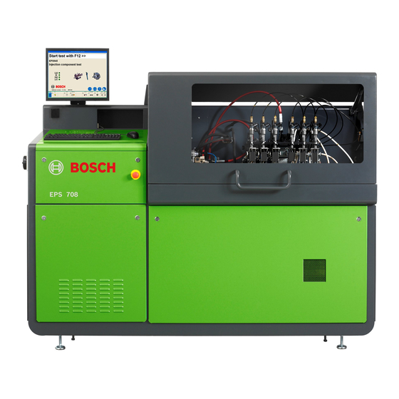
Page 8: Overview Of Eps
8 | EPS 708 | Overview of EPS 708 Overview of EPS 708 Covers Test bench 12 13 Fig. 5: Overview of EPS 708 1 Protective hood with handle Fig. 6: Covers on front 2 Cover of calibrating oil chamber... -
Page 9: Overview Of Electronics Compartment
Overview of EPS 708 | EPS 708 | 9 Overview of electronics 4.3.2 EPS 708 with retrofit kit CP4 (1 687 010 390) compartment 4.3.1 Standard delivery 2 3 4 5 Fig. 9: Overview of electronics compartment 458863-03_Ri 1 Circuit board 1 688 400 452 (A3) -
Page 10: Overview Of Hydraulics Chamber
10 | EPS 708 | Overview of EPS 708 Overview of hydraulics chamber Overview of high-pressure rail 4.6.1 Components 458863-08_Ri Fig. 10: Overview of hydraulics chamber 1 Solenoid valve block for injector delivery quantity 2 Solenoid valve block for injected return quantity... -
Page 11: Overview Of Lubricating-Oil Supply Unit
Overview of EPS 708 | EPS 708 | 11 Overview of lubricating-oil supply unit 458859-1 Fig. 14: EPS 708 rear view 1 Cover plate 2 Lubricating oil intake pressure hose (700 mm) 3 Lubricating oil return pressure hose (850 mm) 4 Circuit board 1 688 400 453... -
Page 12: Overview Of The Water Chiller G1 Electrical Cabinet
12 | EPS 708 | Overview of EPS 708 Overview of the water chiller G1 2 3 4 5 7 8 9 10 11 electrical cabinet 4588963-90_Pal 4588963-91_Pal Fig. 18: View of the inside Fig. 15: Front view 1 Contactor KM1... -
Page 13: Checklist For Normal Operation
Checklist for normal operation | EPS 708 | 13 Checklist for normal operation Status LEDs on components in the test bench provide information about their current operating status. During normal operation (test bench on, no testing), the following states apply:... -
Page 14: Power Packs G3 And G4
14 | EPS 708 | Checklist for normal operation Power packs G3 and G4 In normal operation, the power LEDs of both power packs light up. To check the status, proceed as follows: 1 689 975 233 2018-05-08 Robert Bosch GmbH... -
Page 15: Leds On Pcbs
Checklist for normal operation | EPS 708 | 15 LEDs on PCBs 5.3.2 PCB (A6) The PCBs contain LEDs, which light up in a particular sequence during normal operation (test bench on, no testing). Symbol LED lights up LED lights up at half... - Page 16 16 | EPS 708 | Checklist for normal operation 5.3.3 PCB (A5) 5.3.4 PCB (A4) V96 V98 V24 V26 458863-21_Ri Fig. 22: PCB 1,688,400,451 V1 Firmware status Status Firmware in good working order. No faults occurred 458863-23_Ri Disturbance to 24 V power supply Fig.
- Page 17 Checklist for normal operation | EPS 708 | 17 5.3.5 PCB (A14) Jumper setting for circuit board (A14) Circuit board A14 is included in the scope of delive- ry of retrofit kit CP4 (1 687 010 390) and replaces circuit board A6 when making the conversion.
-
Page 18: Leds On Frequency Converter (A13)
Test 1. Connect the EPS 708 to the voltage network. 2. Switch on the EPS 708 at the main switch. Observe the LED "R" (Fig. 26, item 2b) on the time delay relay K9 immediately after power is switched on. The LED must light up approx. -
Page 19: Repair
4. In the "Injection component test main menu" start screen, select <F7>. A password request appears. Fig. 28: Replacing PCB 1 688 400 452 (A3) in the EPS 708 1958 5. Enter the password in the input line: 6. Confirm your entry with <F12>. -
Page 20: Replacing Pcb (A6)
2014-11 (see Fig. 29) 6.2.1 Removing the PCB 1. Enter the calibration values in the software as fol- 1. Turn off the EPS 708 at the master switch. lows: 2. Secure the master switch so that it cannot be switched back on. -
Page 21: Replacing Pcb (A14)
Replacing PCB 1 688 400 537 (A14) 6.3.1 Removing the PCB 1. Switch off the EPS 708 at the master switch. 2. Secure the master switch so that it cannot be swit- ched back on. 3. Unplug the mains plug or disconnect from mains electricity. -
Page 22: Replacing Pcb (A4)
Replacing PCB 1 688 400 453 (A4) 6.4.1 Removing the PCB 1. Turn off the EPS 708 at the master switch. 2. Secure the master switch so that it cannot be switched back on. 3. Unplug the mains plug or disconnect from mains electricity. -
Page 23: Replacing The Quantity Meter
11. Continue with <F12>. 1. Turn off the EPS 708 at the master switch. 12. Back with <F11>. 2. Secure the master switch so that it cannot be switched back on. -
Page 24: Replacing The Flow Meter
The calibration values are saved and the A leakproof container is required to catch the oil. calibration date is displayed. 1. Turn off the EPS 708 at the master switch. 11. Continue with <F12>. 2. Secure the master switch so that it cannot be 12. -
Page 25: Replacing The Chiller
Get a leakproof container ready for catching cooling water. Note the disposal instructions in section 2.3.2. 1. Turn off the EPS 708 at the master switch. 2. Secure the master switch so that it cannot be switched back on. 3. Unplug the mains plug or disconnect from mains electricity. - Page 26 26 | EPS 708 | Repair 6.7.2 Disconnecting the chiller 6.7.3 Removing the chiller Fig. 38: Disconnecting the chiller Sever any cable ties to expose connecting cables. 1. Disconnect the two connecting cables with green plugs (1 684 463 762 and 1 684 463 727) from the back of the chiller switch box (see Fig.
- Page 27 4. Pull the chiller out of the support frame at the front of the EPS 708 test bench, and place on a firm surface. 5. Remove the control valve from the chiller.
- Page 28 1. Open both valves (Fig. 41, items 1 and 2) on the chiller. Fig. 42: Chiller connection 4. On the back of the EPS 708, route the drain hose (Fig. 43, item 3) into a plastic container or similar (Fig. 43, item 2). 5. Open the tap of the water mains.
- Page 29 3. Close the EPS 708 protective hood. temperatures drop to 30°C. If this is not the case, 4. Start the EPS 708 test bench via the master switch. check the valves on the chiller. 5. Start the EPS945 system software.
-
Page 30: Replacing The Water Pump (M3-P) In The Water Chiller
Secure the main switch so that it cannot be switched back on. ¶ Unplug the mains plug or disconnect the EPS 708 from the mains before opening. 458863-84_Pal 1. Drain the water chiller (see section 6.7.1). Fig. 45: Removing the water connection 1. - Page 31 Repair | EPS 708 | 31 6.8.3 Preparing the water pump 6.8.4 Installing the water pump 1. Place the water pump in the water chiller and secure Flexible corrugated tubing and insulating material it with the aid of washers (4 x) and hex head bolts for insulating the pump are included in the scope of (4 x).
- Page 32 Fig. 49: Chiller connection 3. On the back of the EPS 708, route the drain hose Close the inlet valve (see Fig. 49, item 1). (see Fig. 50, item 3) into a plastic container of the Close the tap of the water mains.
-
Page 33: Replacing The Fan (M2-Ev1) On The Water Chiller
1. Remove the 4 hex head bolts. 6.9.1 Disconnect the fan electrically 1. Switch off the EPS 708 at the main switch. 2. Secure the main switch so that it cannot be swit- ched back on. 3. Unplug the mains plug or disconnect from mains electricity. - Page 34 34 | EPS 708 | Repair 6.9.3 Preparing the fan 6.9.5 Connecting the fan electrically 1. Remove fan from the packaging. 1. Push the connection cable into the electrical cabinet 2. Cut off all wire ferrules at the end of the connection through the cable gland (see Fig.
-
Page 35: Replacing The Controller (A1) Of The Water Chiller
Removing the controller water chiller 6.10.1 Disconnecting the controller 1. Switch off the EPS 708 at the main switch. 2. Secure the main switch so that it cannot be swit- ched back on. 3. Unplug the mains plug or disconnect from mains electricity. - Page 36 " The standard factory parameters are loaded. To ope- 6.10.6 Concluding operations rate the EPS 708, it is necessary to change the para- 1. Check the protective conductor in accordance with meters (see following description). DGUV A3. 2. Switch on EPS 708.
-
Page 37: Replacing The Safety Pressure Switch (Hp1) Of The Water Chiller
6.11.1 Disconnecting the safety pressure switch electrically 1. Switch off the EPS 708 at the main switch. 2. Secure the main switch so that it cannot be swit- ched back on. 3. Unplug the mains plug or disconnect from mains electricity. - Page 38 38 | EPS 708 | Repair When loosening the union nut on the safety pressure After the safety pressure switch has been installed, switch, it is necessary to hold the safety pressure the connection must be checked for leaks with a switch firmly with a second wrench (see Fig.
-
Page 39: Replacing Pressure Switch (Pv1) For The Fan In The Water Chiller
6.12.1 Disconnecting the pressure switch electri- cally 1. Switch off the EPS 708 at the main switch. 2. Secure the main switch so that it cannot be swit- ched back on. 3. Unplug the mains plug or disconnect from mains electricity. - Page 40 40 | EPS 708 | Repair When loosening the union nut on the safety pressure After the pressure switch has been installed, the switch, it is necessary to hold the pressure switch connection must be checked for leaks with a leak firmly with a second wrench (see Fig.
-
Page 41: Replacing The Temperature Sensor (B2) Of The Water Chiller
6.13.1 Disconnecting the temperature sensor elec- trically 1. Switch off the EPS 708 at the main switch. 2. Secure the main switch so that it cannot be swit- ched back on. 3. Unplug the mains plug or disconnect from mains electricity. -
Page 42: Changing The Calibrating Oil
The calibrating oil is now changed. 2. Fit and secure the lid of the calibrating oil tank. 3. Insert the cover and secure. " The EPS 708 is ready for operation. 1 689 975 233 2018-05-08 Robert Bosch GmbH... -
Page 43: Replacing The Electric Fuel Pump
Repair | EPS 708 | 43 6.15 Replacing the electric fuel pump 5. Slacken the two screws on the center segment of the calibrating oil tank lid (see Fig. 70, item 1), take it out of the tank and set down on the leakproof surface. -
Page 44: Replacing The Float Switch
3. Slacken all four screws and remove the float switch 13. Fit the front cover of the calibrating oil chamber. from the tank. Catch and mop up any calibrating oil " The EPS 708 is ready for operation. residues with a cloth. 6.16.2 Installing the float switch ¶... -
Page 45: Replacing The Tank Heater
Repair | EPS 708 | 45 6.17 Replacing the tank heater 6.17.1 Removing the tank heater Fig. 73: Overview of tank lid 1 Terminal cover Fig. 74: Heater 2 Rear segment of calibrating oil tank lid 3 Center segment of calibrating oil tank lid 9. -
Page 46: Replacing The Pneumatic Springs
46 | EPS 708 | Repair 6.18 Replacing the pneumatic springs 6.18.1 Removing the pneumatic springs WARNING - Risk of getting trapped by fal- ling protective hood! There is a risk of getting trapped if the pro- tective hood is not secured. -
Page 47: Replacing The Protective Hood
Repair | EPS 708 | 47 6.19 Replacing the protective hood WARNING - Risk of getting trapped by falling protective hood! There is a risk of getting trapped if the protective hood is not secured. ¶ Always secure the protective hood with the aid of another person. -
Page 48: Replacing The Flywheel
Fig. 80: Flywheel with drive coupling 1. Turn off the EPS 708 at the master switch. 2. Secure the master switch so that it cannot be switched back on. 3. Unplug the mains plug or disconnect from mains electricity. -
Page 49: Replacing The Drive Motor
Secure the master switch so that it cannot be switched back on. ¶ Unplug the mains plug or disconnect the EPS 708 from the mains before opening. ¶ Wait until the discharge time of the drive unit’s DC intermediate circuit (drive motor with converter) has elapsed (<... - Page 50 Removing the drive motor 6.21.2 Installing the drive motor 1. Turn off the EPS 708 at the master switch. 2. Secure the master switch so that it cannot be switched back on. 3. Unplug the mains plug or disconnect from mains electricity.
-
Page 51: Replacing The Pressure Control Valve Block
Removing the valve support Get a cloth ready for catching and mopping up calibrating oil. 1. Turn off the EPS 708 at the master switch. 2. Secure the master switch so that it cannot be switched back on. 3. Unplug the mains plug or disconnect from mains electricity. -
Page 52: Replacing A Pressure Control Valve Of The Pressure Control Valve Block
8. Slacken the pressure limiter again by 90°. 9. Tighten the pressure limiter to 85 +5 Nm. 10. Install the pressure control valve block in the EPS 708 in the reverse order (see section 6.22.3). 1 689 975 233 2018-05-08... -
Page 53: Replacing The Hose Coupling On The Pressure Control Valve Block
(fiber sealing ring or copper sealing ring). 1. Switch off the EPS 708 at the main switch. 2. Secure the main switch so that it cannot be swit- ched back on. max. 6 Nm 15 +2 Nm 3. - Page 54 54 | EPS 708 | Repair 6. Remove the hose coupling (Fig. 92, item 1). When Use the correct tightening torque (see Fig. 93) when loosening the hose coupling, hold the connection tightening the connection fitting. An incorrect tigh- fitting (Fig. 92, item 2) securely with a wrench. Do...
-
Page 55: Replacing The Solenoid Valve Block
2. Remove the hexagon nut (item 1). 3. Remove the solenoid (item 2). 4. Install a new solenoid. 5. Install the solenoid valve block in the EPS 708 in the reverse order. Fig. 95: Pressure control valve block and solenoid valve block 1. -
Page 56: Replacing A Directional Control Valve Of The Solenoid Valve Block
Tightening torque: 1.5 Nm sunk (spot faced). 7. Install the coil (see section 6.27). 8. Install the solenoid valve block in the EPS 708 in the reverse order (see section 6.26.2). max. 6 Nm 15 +2 Nm Fig. -
Page 57: Replacing The Hose Coupling On The Solenoid Valve Block
(see Fig. 101) depends on the sealing ring material (fiber sealing ring or copper sealing 1. Switch off the EPS 708 at the main switch. ring). 2. Secure the main switch so that it cannot be swit- ched back on. -
Page 58: Replacing The Frequency Converter A13 For The Lubricating-Oil Supply Unit
58 | EPS 708 | Repair 6.31 Replacing the frequency converter A13 for the lubricating-oil supply unit One of two different versions of frequency conver- Signal 13 14 DC I< Adj. 15...17V Boost ter A13 is installed. The replacement procedure differs, DC ok X1.3... - Page 59 Repair | EPS 708 | 59 1. Switch off the EPS 708 at the main switch. 2. Secure the main switch so that it cannot be swit- ched back on. 3. Unplug the mains plug or disconnect from mains electricity.
- Page 60 60 | EPS 708 | Repair 3. With the aid of the table, disconnect and remove Disconnecting and removing the connection cable 1 684 465 587 the wires from contactor K8 (see Fig. 102, item 4) to circuit breaker F6:...
- Page 61 Repair | EPS 708 | 61 Installing the frequency converter The new frequency converter and all parts needed to install and connect the new frequency converter are included in conversion kit 1 687 001 990. The new frequency converter A13 (from FD 2015-11) is contained in conversion kit 1 687 023 774 and...
- Page 62 62 | EPS 708 | Repair Installing the time delay relay K9 Connecting the protective conductor Follow the supplied circuit diagram 1 689 911 487. Range Range Time Time Fig. 111: Time relay K9 RUN FWD REV POWER 1. Set the delay time to 10 seconds on the time relay K9 (see Fig.
- Page 63 Repair | EPS 708 | 63 Attaching the M11 three-phase motor If cables U/T1, V/T2 and W/T3 are attached at the wrong points, the three-phase motor will run in- Follow the supplied circuit diagram 1 689 911 487. correctly, and the pump will accumulate little to no pressure.
- Page 64 64 | EPS 708 | Repair 10. Pull the grommet included in the scope of delivery 2. Insert the control terminal connector from below to over the connection cable 1 684 465 810. the rear control terminal of the frequency converter 11. Insert the grommet with connecting cable (see Fig.
- Page 65 Output DC 24V 20A L2 L3 Range Time 380-440Vac Netz Line 1. Switch off the EPS 708 at the main switch. 2. Secure the main switch so that it cannot be swit- 1 L1 3 L2 5 L3 21 NC 1 L1...
- Page 66 66 | EPS 708 | Repair 5. Disconnect the protective conductor (Fig. 123, item 1) from the protective conductor bar of the frequency converter A13. Signal 13 14 DC I< Adj. 15...17V Boost DC ok X1.3 18-29.5V Input 3AC 400-500V Output DC 24V 20A...
- Page 67 Repair | EPS 708 | 67 Installing the frequency converter Connecting the frequency converter A13 1. Fasten the protective conductor (Fig. 126, item 1) The new frequency converter A13 is supplied with a to the protective conductor bar of the frequency parameter set that is designed for the EPS 708.
-
Page 68: Replacing The Oil Metering Unit For The Lubricating Oil Supply
Wire 3 to terminal W 6. Perform safety checks in accordance with national legislation (e.g. DIN VDE 0701-0702 in Germany). 458863-47_Ri 7. Attach all of the covers to the EPS 708. Fig. 128: Lubricating oil supply 1 Oil metering unit 2 Three-phase motor M11... - Page 69 2. Fit the hoses to the lubricating oil supply (see Fig. 130). 3. Using the ratchet extension, install the lubricating oil supply in the EPS 708 with four hexagon bolts and shims (see Fig. 129). Fig. 130: Disconnecting the lubricating oil supply from components 4.
-
Page 70: Replacing The High-Pressure Rail
1. Turn off the EPS 708 at the master switch. 2. Secure the master switch so that it cannot be swit- 7. Remove the cover of the terminal box of the three- ched back on. -
Page 71: Replacing The Pressure Limiter Of The High-Pressure Rail
Repair | EPS 708 | 71 6.34 Replacing the pressure limiter of the 6.35 Replacing the pressure sensor B9/ high-pressure rail B10 of the high-pressure rail 1. Remove the high-pressure rail from the installation panel and take out of the test bench Proceed as described in section 6.33. -
Page 72: Of The High-Pressure Rail
7. Screw the new pressure control valve with O-ring (4) 1. Switch off the EPS 708 at the master switch. into the mounting hole. 2. Secure the master switch so that it cannot be swit- 8. - Page 73 6.38.3 Adjusting temperature sensors 16. Exit the configuration menu by pressing Esc twice. " 1. Switch on the EPS 708 at the master switch. This completes the temperature adjustment. 2. Start the EPS945 system software. The software performs initialization 3.
-
Page 74: Replacing Pressure Sensor B48 Or B49
Tightening torque: 5 +1 Nm 5. Fasten cover on the hydraulics chamber 1. Switch off the EPS 708 at the master switch. (see Fig. 7, item 1). 2. Secure the master switch so that it cannot be swit- 6. Perform zero point adjustment (see section 6.39.3). -
Page 75: Changing The Workstation Light Assembly
Repair | EPS 708 | 75 6.40 Changing the workstation light as- 8. In the test area of EPS 708, remove the hose assem- sembly bly from the appropriate connection (Fig. 142, item 1). 6.40.1 Workstation light removal 1. Switch off the EPS 708 at the main switch. -
Page 76: Changing The Light Fixture Of The Workstation Light
8. Secure the power supply cable using a cable tie. 9. Switch on the EPS 708 using the master switch 10. Check the illumination quality. The illumination can be adjusted by turning the light fixture. -
Page 77: Updating The Parameters Of The Frequency Converter
Updating the parameters of the frequency converter | EPS 708 | 77 Updating the parameters Updating parameters of the frequency converter 7.1.1 Preparatory work 1. Insert Bosch Memory Card in the care reader on the notebook. Important information 2. Insert "Edis" DVD in CD/DVD drive of the notebook. -
Page 78: Printing The Safety Log
78 | EPS 708 | Updating the parameters of the frequency converter Printing the safety log 5. Confirm with <Enter> (Fig. 147, item 2). The new parameter set is loaded. After approx. 1. Connect the printer to the notebook. Load Par from the MMC 30 seconds, "... -
Page 79: Error Messages
Updating the parameters of the frequency converter | EPS 708 | 79 Error messages 13. Select "DRIVE-INTEGRATED SAFETY TECHNOLOGY/ DIAGNOSIS" in the IndraWorks folder structure. Software messages 14. Select <Verify SI parameter>. The safety log opens. 15. Print out the safety log twice. -
Page 80: Error Messages On The Chiller
High-pressure alarm from R Ambient temperature is too high (>45 °C). R EPS 708 placed too close to the wall or the vent grille on the back of the safety pressure switch EPS 708 is obstructed by a bulky object. This reduces the air throughput. -
Page 81: Trouble-Shooting
Trouble-shooting | EPS 708 | 81 Trouble-shooting Trouble-shooting table Effect Cause Remedy Special notes No display on operator Monitor and/or PC not connected Check that both devices are con- unit or switched on. nected and switched on. PC-monitor connecting cable faul-... -
Page 82: Checking The Pressure Control Valve On The High-Pressure Rail
82 | EPS 708 | Trouble-shooting Checking the pressure control valve Hydraulic check: on the high-pressure rail The following three fault situations may occur: The task of the pressure control valves is to generate Somewhat increased rail pressure with non-ener-... - Page 83 Trouble-shooting | EPS 708 | 83 Fault situation 2 Fault situation 3 The test pressure required during measurement cannot Calibrating oil emerges from the pressure control valve be attained although the high-pressure pump is intact. during the pump test. Cause:...
-
Page 84: Checking The Pressure Sensors
Reading out the memory module: ment (redundancy) is also employed as a means of mu- tual monitoring and for checking the 1. Switch on the EPS 708 via the master switch. filter loading. 2. After booting of the PC, start the application EPS945-PE/VE/CR in the Bosch applications list. -
Page 85: Calibrating The High-Pressure Rail
2. Secure the drive coupling 1 686 401 024 (item 3) R Check the connecting 99999 Memory module is to the flywheel of the EPS 708. Tightening torque: not detected cable to the memory modu- le for continuity. 95 ±2 Nm R Replace memory module. - Page 86 2. Attach the USB connecting cable (item 2) to the USB connection X22 (item 1) in the storage compartment of the EPS 708. To do so, route the USB connecting cable under the protective hood. Fig. 154: Hydraulic connection 6.
- Page 87 Calibrating the high-pressure rail | EPS 708 | 87 3. Switch on the EPS 708 via the master switch. 10.1.4 Opening and starting the calibration test sequence 4. Start the EPS945 software. The software performs initialization. 1. In the "Configuration" window, select the menu 5.
- Page 88 88 | EPS 708 | Calibrating the high-pressure rail 10.1.5 Bleeding the high-pressure rail and bringing it 10.1.8 Starting the test to the correct temperature 1. In the "Rail pressure sensor calibration" window, Before the high-pressure rail is calibrated, select <F6>.
-
Page 89: Performing The Zero Point Adjustment Of Pressure Sensors
5. Confirm your entry with <F12>. 6. Select menu item "Calibration >> EPS708". 7. Continue with <F12>. 8. In the test area of EPS 708, remove the hose assem- blies from both test oil connections (Fig. 157, item 1). The test connections (Fig. -
Page 90: Current Calibration
— ● ● ● Supplied with EPS 708 up to date of manufacture 2013-05 (see Edis Info 201307_065). Supplied with EPS 708 from date of manufacture 2013-06 (see Edis Info 201307_065). Supplied with retrofit kit CP4 (1 687 010 390) from date of manufacture 2014-10 and with EPS 708 from date of manufacture 2014-12. - Page 91 Calibrating the high-pressure rail | EPS 708 | 91 6. Switch on multimeter and set the direct-current 10. Open the protective hood of the EPS 708. measuring mode. 11. Switch adapter cable 1 684 460 291 to the EAV/ 7. Set the appropriate measuring range (> 900 mA) DMV2 plug of the connecting cable (X24).
-
Page 92: 11. History
92 | EPS 708 | History 11. History Date Compiled by Change 2018-05-08 Pal Corrections from content in table from chapter 9.4 2017-09-25 Pal Added chapter "Changing the workstation light assembly " and "Changing workstation light" New note for time relay K9. -
Page 93: 12. Annexes
Annexes | EPS 708 | 93 12. Annexes Overview of chiller Hydraulic diagram Circuit diagrams for EPS 708 Version 04.04.11 Version 15.07.14 (without electrical safety socket X21 and with suplemantary set CP4) Version 22.10.15 (new lubricating-oil supply unit) Connection diagram CP4 Circuit diagrams for chiller 12.1... - Page 95 Water- Tank- Light Socket-Outlet Option: Chiller Heating _int. _ext. Lubricant- GN/YE Oil-Pump_AC EPS708 - 380/400/415/440V EPS708 - 200/220/230/240V Datum Robert Bosch GmbH Netzanschluss / Antrieb 1689 911 487 Bearb. 68S01133-21 04.04.2011 EPS708 Gepr. 04.04.11 Stromlaufplan 68S03311-15 19.11.2010 nderung Datum Name Norm Urspr.
- Page 96 /6.4 /6.0 Lfter: zu Montw.1 zu R1 zu Chiller zu M1 zu LPs Power-Supply Power-Supply EKP / DRV Boards, Valves, Contactors Datum Robert Bosch GmbH Stromversorgungen 1689 911 487 Bearb. 68S01133-21 04.04.2011 EPS708 Gepr. 04.04.11 Stromlaufplan 68S03311-15 19.11.2010 nderung Datum...
- Page 97 24V- Hauben-Kontakte Sensor Antrieb Khler -ein -Takt G2 (15V) Oil_AC Ventil Drive- Chiller- Hood-Switches Contactor Contactor Datum Robert Bosch GmbH NOT-AUS & Sicherheitskreis 1689 911 487 Bearb. 68S01133-21 04.04.2011 EPS708 Gepr. 04.04.11 Stromlaufplan 68S03311-15 19.11.2010 nderung Datum Name Norm Urspr.
- Page 98 1.4A ZME01 4.4/ ZME02 4.4/ EKP1 EKP2 EKP3 DRV1 DRV2 DRV3 DRV01 4.4/ DRV02 4.4/ DMV2 Datum Robert Bosch GmbH Powerboard_1 1689 911 487 Bearb. 68S01133-21 04.04.2011 EPS708 Gepr. 04.04.11 Stromlaufplan 68S03311-15 19.11.2010 nderung Datum Name Norm Urspr. Ers. f.
- Page 99 Tank KEM/PLU m.Flansch Khlung Proportional valve Bypass CP-Volume CP-Volume Cooling- not used CP-Backflow CP-Backflow to PLU Valve Datum 01.09.09 Robert Bosch GmbH Powerboard_2 1689 911 487 Bearb. 68S01133-21 04.04.2011 EPS708 Gepr. 04.04.11 Stromlaufplan 68S03311-15 19.11.2010 nderung Datum Name Norm Urspr.
- Page 100 X301 X302 black blue SUPPLY+ X320 X320 4.4/ /9.1 SUPPLY- 4.4/ Valve Control-Board 1688 400 480 8-Pin Datum Robert Bosch GmbH Valve-Block 1689 911 487 Bearb. 68S01133-21 04.04.2011 EPS708 Gepr. 04.04.11 Stromlaufplan 68S03311-15 19.11.2010 nderung Datum Name Norm Urspr. Ers. f.
- Page 101 4-20mA RDS1 RDS2 Rail Tank Sensor Sensor Sensor Sensor Sensor opt. Input Becker-Back- KEM-Flow- Flow-Sensor Sensor Datum Robert Bosch GmbH Interface & Microblaze-Bd. 1689 911 487 Bearb. 68S01133-21 04.04.2011 EPS708 Gepr. 04.04.11 Stromlaufplan 68S03311-15 19.11.2010 nderung Datum Name Norm Urspr.
- Page 102 Water- Tank- Light Socket-Outlet Option: Chiller Heating _int. Lubricant- GN/YE Oil-Pump_AC EPS708 - 380/400/415/440V EPS708 - 200/220/230/240V Datum 11.06.14 Robert Bosch GmbH Netzanschluss / Antrieb 1689 911 487 1680S00746 11.06.2014 Bearb. 1680S00392 15.01.2013 EPS708 Stromlaufplan Gepr. 15.07.14 1680S00277 20.09.2012 088/TEF6 Žnderung...
- Page 103 R1 zu Chiller Nachrstsatz CP4 zu M1 zu LPs (F32 und X2.18) Power-Supply Power-Supply EKP / DRV Boards, Valves, Contactors Datum 11.06.14 Robert Bosch GmbH Stromversorgungen 1689 911 487 1680S00746 30.06.2014 Bearb. ECT1-EU-Ge. 1680S00392 15.01.2013 EPS708 Stromlaufplan Gepr. 15.07.14 1680S00277 20.09.2012...
- Page 104 DILMC 7 14 .1 2 4.0 2 4.4 14 .3 24 .1 4 4.1 4 4.4 24 .1 6 4.1 Datum 11.06.14 Robert Bosch GmbH NOT-AUS & Sicherheitskreis 1689 911 487 1680S00746 11.06.2014 Bearb. 1680S00392 15.01.2013 EPS708 Stromlaufplan Gepr. 15.07.14 1680S00277 20.09.2012...
- Page 105 1.4A ZME01 4.4/ ZME02 4.4/ EKP1 EKP2 EKP3 DRV1 DRV2 DRV3 DRV01 4.4/ DRV02 4.4/ DMV2 Datum 11.06.14 Robert Bosch GmbH Powerboard_1 1689 911 487 1680S00746 11.06.2014 Bearb. 1680S00392 15.01.2013 EPS708 Stromlaufplan Gepr. 15.07.14 1680S00277 20.09.2012 088/TEF6 Žnderung Datum Name Norm Urspr.
- Page 106 Tank KEM/PLU m.Flansch Khlung Proportional valve Bypass CP-Volume CP-Volume Cooling- not used CP-Backflow CP-Backflow to PLU Valve Datum 01.09.09 Robert Bosch GmbH Powerboard_2 1689 911 487 1680S00746 11.06.2014 Bearb. 1680S00392 15.01.2013 EPS708 Stromlaufplan Gepr. 15.07.14 1680S00277 20.09.2012 088/TEF6 Žnderung...
- Page 107 X301 X302 black blue SUPPLY+ X320 X310 /9.1 SUPPLY- Valve Control-Board 1688 400 480 8-Pin Datum 11.06.14 Robert Bosch GmbH Valve-Block 1689 911 487 1680S00746 11.06.2014 Bearb. 1680S00392 15.01.2013 EPS708 Stromlaufplan Gepr. 15.07.14 1680S00277 20.09.2012 088/TEF6 Žnderung Datum Name Norm Urspr.
- Page 108 RDS1 RDS2 Rail Tank Sensor Sensor Sensor Sensor Sensor opt. Input Becker-Back- KEM-Flow- Flow-Sensor Sensor Datum 11.06.14 Robert Bosch GmbH Interface & Microblaze-Bd. 1689 911 487 1680S00746 11.06.2014 Bearb. 1680S00392 15.01.2013 EPS708 Stromlaufplan Gepr. 15.07.14 1680S00277 20.09.2012 088/TEF6 Žnderung Datum...
- Page 109 Tank- Light Socket-Outlet Option: Chiller Heating _int. Lubricant- GY GN/YE Oil-Pump_AC EPS708 - 380/400/415/440V EPS708 - 200/220/230/240V 1689 911 487 Robert Bosch GmbH NETZANSCHLUSS / ANTRIEB 1680S01047 22.10.2015 Datum 06.10.2004 1680S00392 15.01.2013 Bearb. ENG13-EU-Ge. Stromlaufplan EPS708 1680S00277 20.09.2012 Gepr. 22.10.2015 DIN A3 Änderung...
- Page 110 R1 zu Chiller Nachrüstsatz CP4 zu M1 zu LPs (F32 und X2.18) Power-Supply Power-Supply EKP / DRV Boards, Valves, Contactors 1689 911 487 22.10.2015 Robert Bosch GmbH STROMVERSORGUNGEN 1680S01047 Datum 06.10.2004 1680S00392 15.01.2013 Bearb. ENG13-EU-Ge. EPS708 Stromlaufplan 1680S00277 20.09.2012 Gepr.
- Page 111 Lube- Tank- Antrieb Kühler -ein -Takt G2 (15V) Oil_AC Sensor Drive- Chiller- Contactor Contactor 1689 911 487 22.10.2015 Robert Bosch GmbH NOT-AUS & SICHERGHEITSRELAIS 1680S01047 Datum 06.10.2004 1680S00392 15.01.2013 Bearb. ENG13-EU-Ge. EPS708 Stromlaufplan 1680S00277 20.09.2012 Gepr. 22.10.2015 DIN A3 Änderung...
- Page 112 EKP1+ EKP2+ EKP3+ 1.4A 1.4A 1.4A ZME01 ZME02 EKP1 EKP2 EKP3 DRV1 DRV2 DRV3 DRV01 DRV02 1689 911 487 Robert Bosch GmbH POWERBOARD_1 22.10.2015 Datum 06.10.2004 1680S01047 Bearb. ENG13-EU-Ge. 1680S00392 15.01.2013 Stromlaufplan EPS708 1680S00277 20.09.2012 Gepr. 22.10.2015 DIN A3 088/TEF6 Änderung...
- Page 113 KEM/PLU m.Flansch Kühlung Proportional valve Bypass CP-Volume CP-Volume Cooling- not used CP-Backflow CP-Backflow to PLU Valve 1689 911 487 22.10.2015 Robert Bosch GmbH POWERBOARD_2 1680S01047 Datum 06.10.2004 1680S00392 15.01.2013 Bearb. ENG13-EU-Ge. EPS708 Stromlaufplan 1680S00277 20.09.2012 Gepr. 22.10.2015 DIN A3 Änderung...
- Page 114 X301 X302 black blue SUPPLY+ X320 X310 / 9.1 SUPPLY- Valve Control-Board 1688 400 480 1689 911 487 Robert Bosch GmbH VALVE-BLOCK 22.10.2015 Datum 06.10.2004 1680S01047 Bearb. wog2pl 1680S00392 15.01.2013 Stromlaufplan EPS708 1680S00277 20.09.2012 Gepr. 22.10.2015 DIN A3 Änderung Datum...
- Page 115 RDS1 RDS2 Rail Tank Sensor Sensor Sensor Sensor Sensor opt. Input Becker-Back- KEM-Flow- Flow-Sensor Sensor 1689 911 487 Robert Bosch GmbH INTERFACE & MICROBLAZE-BOARD 1680S01047 22.10.2015 Datum 06.10.2004 1680S00392 15.01.2013 Bearb. wog2pl Stromlaufplan EPS708 1680S00277 20.09.2012 Gepr. 22.10.2015 DIN A3 Änderung...
- Page 116 Druck / Temp. CP Pumpe Venturi-Messung CP4 Transferdruck Temp. Pressure / Temp. Pressure / Temp. CP Pump Venturi-Measurement CP4 Transfer-pressure 1.Verw.: 1687 010 390 Robert Bosch GmbH HAUPTSTROM Datum 11.06.2014 Bearb. ECT1-EU-Ge. Nachrüstsatz CP4/708 Anschlussplan 1689 927 302 1680S00855 17.10.14 Gepr.
- Page 117 (BU) blau (BU) blau (BU) blau (BU) schwarz (BK) blau (BU) grün (GN) grün (GN) grün (GN) rot (RT) rot (RT) Robert Bosch GmbH VENTILE Datum 11.06.2014 1.Verw.: 1687 010 390 Bearb. ECT1-EU-Ge. Nachrüstsatz CP4/708 Anschlussplan 1689 927 302 1680S00855 17.10.14...
- Page 126 Robert Bosch GmbH Diagnostics Franz-Oechsle-Straße 4 73207 Plochingen DEUTSCHLAND www.bosch.com bosch.prueftechnik@bosch.com 1 689 975 233 | 2018-05-08...