Table of Contents
Advertisement
Advertisement
Table of Contents

Related Manuals for Delta RPI M50A_120


Summary of Contents for Delta RPI M50A_120
- Page 1 Installation and Operation Manual RPI M50A_120 RPI M50A_122 Europe...
- Page 2 The technical instructions and illustrations in this manual are to be treated as confidential and no part of this manual may be reproduced without prior written permission from Delta Energy Systems. Maintenance technicians and end users may not release the informa- tion contained in this manual, and may not use it for purposes not directly associated with the proper use of the solar power inverter.
-
Page 3: Table Of Contents
Table of Contents Table of Contents 1. About this manual ........... . 5 Purpose of this manual. - Page 4 Table of Contents 6.7.2 Dry contacts ........... 47 6.7.3 Digital inputs and EPO .
-
Page 5: About This Manual
The solar inverter can be safely and normally oper- ated if installed and used in accordance with this NOTICE manual. Delta Energy Systems is not responsible for ATTENTION is used to address practices not damage incurred by failure to comply with the installa- related to physical injury. -
Page 6: Conventions Used In This Manual
1. About this manual Conventions used in this manual Order of instructions Numbered instructions must be performed in the specified order. First instruction step → When the solar inverter reacts to a step, this reaction is marked with an arrow. Second instruction step Third instruction step Instructions consisting of only one step or when the... -
Page 7: General Safety Instructions
DC connections of the solar must be maintained or repaired by the operator or inverter. When light is falling on solar installer. All repairs must be performed by Delta modules, they immediately start pro- Energy Systems. Opening the cover will void the ducing energy. -
Page 8: Intended Use
3. Intended use Intended use The solar inverter may only be used as intended. Proper use of the solar inverter meets the following criteria: ● Use in stationary PV systems connected to the local power grid for converting the direct current in the PV system to alternating current and feeding it into the grid ●... - Page 9 3. Intended use Installation and Operation Manual for RPI M50A...
-
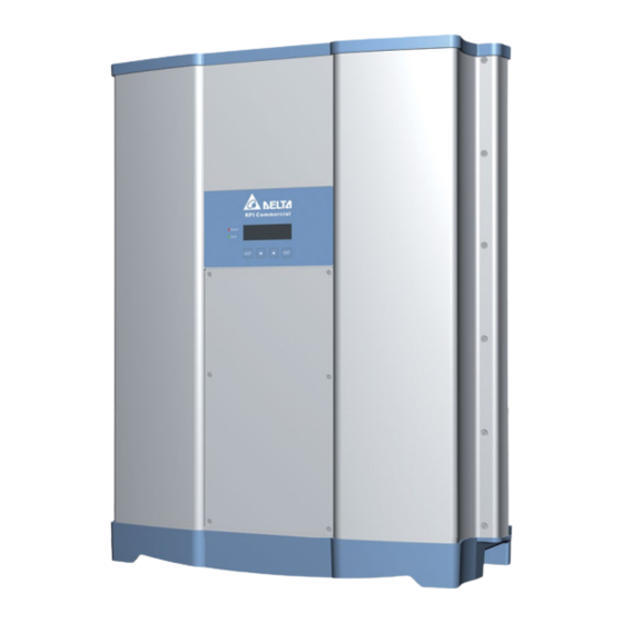
Page 10: Product Overview
4. Product overview Product overview Scope of delivery Part Image/Description Part Image/Description Inverter DC bus bar Used when the solar mod- ules have to be grounded and for connecting the two DC inputs to one MPP tracker. Mounting plate DC Fuse holder 1 Used when the solar mod- ules have to be grounded. -
Page 11: Components And Connectors
4. Product overview Components and connectors Component / connector Description Display, buttons, status LEDs “4.3 Display, buttons, status LEDs”, p. 12 “4.4 String fuses and AC/DC surge protection String fuses and AC/DC overvoltage protection device”, p. 12 Air inlets “4.5 Air inlets and fans”, p. 13 Electrical connectors “4.6 Electrical connectors”, p. -
Page 12: Display, Buttons, Status Leds
4. Product overview Display, buttons, status LEDs Alarm Grid Label Designation Usage LEDs Grid Green; lights up when the inverter feeds into the grid Alarm Red; indicates and error, fault, or warning lArm Buttons Escape Exit current menu. Cancel value setting. Move down Move downwards in menu. -
Page 13: Surge Protection Devices
4. Product overview Surge protection devices Air inlets and fans Air is intaken from the environment through the air 4.5.1 AC side inlets on the upper left and upper right side of the inverter. The air is used to cool the inverter. The The M50A_120 additionally has surge protection warmed-up air is ejected at the fans on the bottom devices type 2 on the AC and the DC side. -
Page 14: Electrical Connectors
4. Product overview Electrical connectors 4.7.1 Overview – – – – DISCONN. AC/DC DC 1 DC 2 COMM. AC OUTPUT DC INPUT Fig. 4.1: Overview electrical connectors Component / connector Description AC/DC disconnection switch “4.6.2 AC/DC disconnection switch”, p. 15 AC connector (AC output) “4.6.3 AC connector (AC output)”, p. -
Page 15: Ac/Dc Disconnection Switch
4. Product overview 4.7.2 AC/DC disconnection switch 4.7.4 DC connectors (DC inputs) – – – – DC 1 DC 2 DISCONN AC/DC DC INPUT The DC connectors (DC inputs) are used for connect- The inverter is disconnected from the grid (AC) and ing inverter to the solar module string(s). -
Page 16: Communication Port 2
4. Product overview 4.7.6 Communication port 2 – DC 2 COMM. Communication port 2 is not available on this inverter. 4.7.7 Grounding connection DISCONN. AC/DC The grounding connection is used for grounding the housing of the inverter. The grounding screw (M6) with washer spring, washer and toothed ring is already mounted to the inverter. -
Page 17: Information On The Type Label
4. Product overview Information on the type label Fig. 4.2: RPI M50A_120 type label Fig. 4.3: RPI M50A_122 type label Information on type label Description This inverter has no transformer. Risk of death by electrocution Potentially fatal voltage is present when the inverter is in operation that remains for 10 seconds after being disconnected from power. -
Page 18: Planning The Installation
5 Planning the installation Planning the installation NOTE This chapter is for planning the instal- lation only and is not related to do any real actions. Some of the actions can be danger- ous. Chapter “6. Installation”, p. 37 describes all actions and the possibly ✘... -
Page 19: Outdoor Installations
5 Planning the installation Outdoor installations Ambient conditions and air circula- tion >30 cm >30 cm >30 cm Fig. 5.4: Outdoor installations Fig. 5.5: Mounting distances and air circulation ► The solar inverter has protection degree IP65 and ► Ensure adequate air circulation. Hot air must be can be installed indoors or in protected outdoor able to dissipate downward. -
Page 20: Temperature Derating Curves
5 Planning the installation Temperature derating curves S [VA] = P [W] 800 V 600 V = 50 kW) 520 V 115% 110% 105% 100% Ambient temperatures [°C] Fig. 5.6: Temperature derating curve (cos φ = 1.0) Installation and Operation Manual for RPI M50A... - Page 21 5 Planning the installation S [VA] P [W] 800 V 800 V 600 V 600 V = 50 kW) 520 V 520 V 115% 110% 105% 100% Ambient temperatures [°C] Fig. 5.7: Temperature derating curve (cos φ = 0.95) Installation and Operation Manual for RPI M50A...
- Page 22 5 Planning the installation S [VA] P [W] 800 V 800 V 600 V 600 V = 50 kW) 520 V 520 V 115% 110% 105% Ambient temperatures [°C] Fig. 5.8: Temperature derating curve (cos φ = 0.90) Installation and Operation Manual for RPI M50A...
-
Page 23: Efficiency Curve
5 Planning the installation Efficiency curve 800 V 600 V Efficiency 520 V 100% Power [kW] Fig. 5.9: Efficiency curve Installation and Operation Manual for RPI M50A... -
Page 24: Dimensions
5 Planning the installation Dimensions Fig. 5.10: Dimensions of mounting plate Fig. 5.11: Dimensions of inverter Installation and Operation Manual for RPI M50A... -
Page 25: Ac Connection
The inverter is not capable of feeding in DC residual cur- rents due to its design. It fulfills this requirement in accor- dance with DIN VDE 0100-712. The possibilities of faults were examined by Delta without taking the integrated RCMU (residual-current monitoring unit) into account. When examining... -
Page 26: Dc Connection
5 Planning the installation DC connection NOTICE Machine and equipment damage may occur. Exceeding the maximum current per DC input can cause an overheating of the DC inputs. ► Always consider the maximum current of the DC inputs when planning the installation. 5.8.1 Symmetrical and asymmetrical power input The inverter operates using two separate MPP trackers that can handle both symmetrical and asymmetrical power input. -
Page 27: Use With Solar Modules That Do Not Need To Be Grounded
5 Planning the installation For currents and voltages see “13. Technical data”, p. 105. 5.8.2 Use with solar modules that do not need to be grounded. When you use PV modules that do not need to be grounded, you can connect the DC inputs separately or in parallel. -
Page 28: Use With Solar Modules That Have To Be Grounded
“6.5 Connecting to the solar modules (DC)”, must be connected in parallel and then connected to the inverter(s). PV array AC wiring Utility 3-phase, 230/400 V star or delta connection DC wiring Isolated transformer Distribution Box Positive grounding Inverter 230/400 V... - Page 29 5 Planning the installation DC1+ DC2+ Fuse holder DC bus bar DC1- Grounding fuse (1 A) DC2- Fig. 5.17: Preparing the inverter for use with minus grounded solar modules Fuse holder and DC bus bars are delivered with the inverter. The screws are already fastened inside the inverter.
- Page 30 5 Planning the installation DC1+ DC2+ Fuse holder DC bus bars DC1- Grounding fuse (1 A) DC2- Fig. 5.18: Preparing the inverter for use with plus grounded solar modules Fuse holder and DC bus bars are delivered with the inverter. The screws are already fastened inside the inverter.
-
Page 31: Using Dc1 And Dc2 With Only One Mpp Tracker
5 Planning the installation 5.8.4 Using DC1 and DC2 with only one MPP tracker When you want to use DC1 and DC2 with only one MPP tracker, you have to prepare the inverter as shown in Fig. 5.19, p. Because you have to remove the cover of the fuse section, you should do this before you hang the inverter on the wall and do it in a dry environment. -
Page 32: Connecting To A Datalogger Via Rs485
5 Planning the installation Connecting to a datalogger via RS485 The inverter can be connected to a datalogger via RS485, e.g. for monitoring, changing settings or soft- ware updates. To ensure the proper work of the data connection, consider the following recommendation and instruc- tions. -
Page 33: Circuit Diagram Of String Fuses And Spds
5 Planning the installation 5.10 Circuit diagram of string fuses and SPDs DC1+ DC1– DC2+ DC2– DC side AC side Overvoltage protection category II Overvoltage protection category II Fig. 5.20: Circuit diagram string fuses and surge protection devices String fuse Surge protection device Installation and Operation Manual for RPI M50A Installation and Operation Manual for RPI M50A... -
Page 34: What You Need
5 Planning the installation 5.11 What you need Beside the parts delivered with the inverter (see “4.1 Scope of delivery”, p. 10), you may need the following addititional parts and tools. Part Quantity Image/Description For mounting the inverter M6 mounting screws The mounting plate has to be mounted with 12 M6 screws. - Page 35 5 Planning the installation Part Quantity Image/Description Wire ferrules (bootlace 4 or 5 Wire ferrules are needed for the wires of the AC cable to tightly mount pins) and crimping tool them to the AC connector. 4 (for 3-wire systems with 3 phases + PE) 5 (for 4-wire systems with 3 phases + N + PE) You should use a crimping tool to fasten the wire ferrules to the wire.
- Page 36 5 Planning the installation Part Quantity Image/Description Open end spanner The open end spanner is used to disconnect the DC cables from the DC inputs. For grounding the inverter housing Cables Typically yellow/green copper cable with minimum wire size 6 mm has to be used.
-
Page 37: Installation
6 Installation Installation Safety instructions DANGER High electrocution Potentially fatal voltage is applied to the solar inverter during operation. This potentially fatal voltage is still present for 10 seconds after all power sources have been disconnected. ► Always disconnect the inverter from power before installation, open the AC/DC isolating switch and make sure neither can be accidentally... -
Page 38: Mounting The Inverter
6 Installation Mounting the inverter Check that the rail of the solar inverter hangs cor- rectly in the mounting plate. WARNING Heavy weight ► The inverter must be lifted and car- ried by at least three people or with an appropriate lifting equipment. ►... -
Page 39: Grounding The Inverter Housing
6 Installation Grounding the inverter housing Typically yellow/green copper cable with minimum wire size 6 mm has to be used. Always consider local regulation regarding the cable requirements. Even when such regulations do not exist, it is usually a good idea to ground the inverter housing for safety reasons before you set-up the electricial connections. -
Page 40: Connecting To The Grid (Ac)
6 Installation Connecting to the grid (AC) Important information regarding safety Read chapter “5. Planning the installa- DANGER tion”, p. 18 before you start installa- tion. Risk of death or serious injury from electrocution ► Set the AC/DC disconnection switch What you need to position OFF before connecting or disconnecting the AC plug to the... - Page 41 6 Installation ► Slide the wires of the AC cable into the connec- ATTENTION tions in the pin insert and screw tight. Observe the Observe the correct polarity of the AC correct phase sequence when doing this. plug. An incorrect confi guration can ➀...
-
Page 42: Connecting To The Solar Modules (Dc)
6 Installation Connecting to the solar modules NOTICE (DC) Machine and equipment damage may occur. Read chapter “5. Planning the installa- Exceeding the maximum current per tion”, p. 18 before you start installa- DC input can cause an overheating of tion. -
Page 43: Using Dc1 And Dc2 With Only One Mpp Tracker (Optional)
6 Installation Using DC1 and DC2 with only one Connector types MPP tracker (optional) The Multi-Contact MC4 are delivered with the inverter. The plugs can also be ordered from Multi-Contact Only when you want to use DC1 and DC2 on one at www.multi-contact.de. - Page 44 6 Installation Mount one DC bus bar to connect the DC1+ bar Fasten the six screws to the fuse section cover. and the DC2+ bar. Mount the other DC bus bar with two DC bar screws to connect the DC1– bar and the DC2– bar.
-
Page 45: Connecting Communication Port I (Optional)
For connecting RS485, Pins 3 to 6 are used. If you want to use SOLIVIA Monitor, the Internet DC 2 based monitoring from Delta, you will also need a COMM. SOLIVIA M1 G2 Gateway. Default baud rate is 19200 which can be changed on Fig. - Page 46 6 Installation Switch for VCC and termination resistor Termination resistor Connecting a single inverter to a datalogger Connecting multiple inverters to a datalogger If your datalogger has no integrated termination resistor, switch on the termination resistor on the first inverter in the RS485 line.
-
Page 47: Dry Contacts
6 Installation 6.7.2 Dry contacts 6.7.3 Digital inputs and EPO When the fans fail, Dry contact 1 is closed. The digital inputs can be used to connect an external When the inverter feeds into the grid, Dry contact 2 is ripple control receiver for controlling the active power. -
Page 48: Wiring Communication Port 1
6 Installation Wiring communication port 1 6.8.1 First steps for all cables Because all communication cables are connected to the same communication port, you should do the complete wiring at once. Unscrew and remove the bolting. Pull all cables you want to connect through the bolting. -
Page 49: Wiring Multiple Inverters For Rs 485
6 Installation Switch on DIP switch 2 to turn on the termination On the second inverter, connect the cable that resistor. comes from the fi rst inverter and the cable that goes to the next inverter. Repeat these steps for all other inverters in the RS485 chain, except for the last inverter. -
Page 50: Wiring The Dry Contacts
6 Installation 6.8.4 Wiring the dry contacts 6.8.6 Finishing the wiring Depending on how many cables you connected and You can use both dry contacts or only one. whether it is a single inverter or an inverter in a chain of multiple inverters, the fi nal wiring could look like shown in the following two images. -
Page 51: Putting Labels On The Inverter
6 Installation Putting labels on the inverter Screw the bolting onto the cover. After fi nishing the installation, you have to put all necessary labels onto the inverter. Check local regu- lations about which labels are needed. See some samples below. Do not work on this equipment until it is isolated from WARNING both mains and on site generation supplies... -
Page 52: Commissioning
7. Commissioning Commissioning The inverter must be correctly installed, see “6. Installation”, p. For information on how the display is operated, see “4.3 Display, buttons, status LEDs”, p. To execute commissioning, the inverter needs to be powered either by AC (the grid) or DC (the solar modules). -
Page 53: Settings
8 Settings Settings Overview Current grid settings (inverter information) Display language Date and time Baud rate for RS485 Inverter ID Insulation mode and insulation resistance Grid settings EPO (External Power Off) 8.10 AC Connection type 8.11 Max. Power (Maximum feed-in power) 8.12 Power limitation 8.13 Power versus frequency 8.14 Constant cos phi... -
Page 54: Current Grid Settings (Inverter Information)
8 Settings Current grid settings (inverter information) Overview With this function you can see the current settings of the solar inverter. Accessing the menu Main menu > Inverter info. When the default information is displayed, press any button to open the 1 0 . -
Page 55: Display Language
8 Settings Display language Overview With this function you can set the language used in the display. Accessing the menu Main menu > General settings > Language When the default information is displayed, press any button to open the 1 0 . S e p 2 0 1 4 1 5 : 3 2 S t a t u s : O n G r i d main menu. -
Page 56: Date And Time
8 Settings Date and time Overview With this function you can set date and time. ► For a precise calculation of the statistics in the inverter itself and in a monitoring system, date and time have to be correct. Accessing the menu Main menu >... -
Page 57: Baud Rate For Rs485
8 Settings Baud rate for RS485 Overview With this function you can set the baud rate for the RS485 connection. ► If you connect multiple inverters via RS485, set the same baud rate on each inverter. Accessing the menu Main menu > General settings > Baud rate When the default information is displayed, press any button to open the 1 0 . -
Page 58: Inverter Id
8 Settings Inverter ID Overview With this function you can set an ID for the inverter. The inverter ID is used to identify the inverter in a RS485 connection. The inverter ID is also used in monitoring systems. ► Set a different inverter ID for each inverter in the PV plant. Otherwise, the inverters cannot be correctly identifi ed. -
Page 59: Insulation Mode And Insulation Resistance
1 1 0 0 k Ω To confi rm your selection, press the button Do not change this setting without prior consultation with Delta Solar Support. Installation and Operation Manual for RPI M50A Installation and Operation Manual for RPI M50A... - Page 60 Resistance Insulation resistance 150 kΩ | 250 kΩ | 1100 kΩ Default: 1100 kΩ Do not change this setting without prior consultation with Delta Solar Support. Installation and Operation Manual for RPI M50A Installation and Operation Manual for RPI M50A...
-
Page 61: Grid Settings
Delta Support when you want to change these settings. This function is protected by a special password. To get the password, please call the Delta Sup- port hotline in your country. You can fi nd the telephone number on the last page of this document. - Page 62 Disconnection time for Voltage Low Off Slow Table 8.1.: Confi gurable parameters for Grid settings > Voltage Protection Do not change this setting without prior consultation with Delta Solar Support. Installation and Operation Manual for RPI M50A Installation and Operation Manual for RPI M50A...
-
Page 63: Frequency Protection
A c t i v e / R e a c t i v e P w r F R T Type in the password you received from Delta Support. Use the buttons to set each digit. To confi rm a digit, press the button... - Page 64 Disconnection time for Frequency Low Off Slow Table 8.2.: Configurable parameters for Grid settings > Frequency Protection Do not change this setting without prior consultation with Delta Solar Support. Installation and Operation Manual for RPI M50A Installation and Operation Manual for RPI M50A...
-
Page 65: Reconnection Time
A c t i v e / R e a c t i v e P w r F R T Type in the password you received from Delta Support. Use the buttons to set each digit. To confi rm a digit, press the button... -
Page 66: P Ramp Up
A c t i v e / R e a c t i v e P w r F R T Type in the password you received from Delta Support. Use the buttons to set each digit. To confi rm a digit, press the button... -
Page 67: Epo (External Power Off)
8 Settings EPO (External Power Off) Overview With this function you can set the type of contact for the EPO function (normally open or normally closed). Accessing the menu Main menu > Install Settings > EPO When the default information is displayed, press any button to open the 1 0 . -
Page 68: Ac Connection Type
8 Settings 8.10 AC Connection type Overview With this function you can set the type of AC connection you use to connect the inverter to the grid. The inverter can be connected to a 3-wire system (3P3W: L1, L2, L3, PE) or a 4-wire system (3P4W: L1, L2, L3, N, PE). The default setting is 3P4W. -
Page 69: Max. Power (Maximum Feed-In Power)
8 Settings 8.11 Max. Power (Maximum feed-in power) Overview This function should be set only when requested by country regulations, authorities or your grid operator. With this function you can limit the maximum active power to be fed into the grid. Accessing the menu Main menu >... -
Page 70: Power Limitation
P o w e r v s . F r e q u e n c y To confi rm your selection, press the button P ( V ) Do not change this setting without prior consultation with Delta Solar Support. Installation and Operation Manual for RPI M50A Installation and Operation Manual for RPI M50A... - Page 71 The value for the power limitation. Set Point 0 .. 100% Default value: 100% Do not change this setting without prior consultation with Delta Solar Support. Installation and Operation Manual for RPI M50A Installation and Operation Manual for RPI M50A...
-
Page 72: Power Versus Frequency
R e a c t i v e P o w e r C t r l setting is displayed behind the menu entry. Do not change this setting without prior consultation with Delta Solar Support. Installation and Operation Manual for RPI M50A Installation and Operation Manual for RPI M50A... - Page 73 When the grid frequency drops to F Recovery, the inverter will wait for the time defi ned in T Recovery before it returns to normal operating behavior. Do not change this setting without prior consultation with Delta Solar Support. Installation and Operation Manual for RPI M50A Installation and Operation Manual for RPI M50A...
-
Page 74: Constant Cos Phi
I n d 1 . 0 0 to select Cos phi and press the button Do not change this setting without prior consultation with Delta Solar Support. Installation and Operation Manual for RPI M50A Installation and Operation Manual for RPI M50A... - Page 75 Sets up a cos phi so that the inverter can feed reac- Cos phi ind 0.8 ... cap 0.8 tive power into the grid. Do not change this setting without prior consultation with Delta Solar Support. Installation and Operation Manual for RPI M50A Installation and Operation Manual for RPI M50A...
-
Page 76: Cos Phi (P)
C o n s t a n t Q Q ( V ) Do not change this setting without prior consultation with Delta Solar Support. Installation and Operation Manual for RPI M50A Installation and Operation Manual for RPI M50A... - Page 77 The upper limit of the grid voltage range in which the function is active. The param- V lock-out eter is used for Italy only. Do not change this setting without prior consultation with Delta Solar Support. Installation and Operation Manual for RPI M50A Installation and Operation Manual for RPI M50A...
-
Page 78: Constant Q
I n d 9 0 % to select the parameter and press the button Do not change this setting without prior consultation with Delta Solar Support. Installation and Operation Manual for RPI M50A Installation and Operation Manual for RPI M50A... - Page 79 Sets up a constant reactive power which is set in per cent of the nominal apparent Fix Q power S Do not change this setting without prior consultation with Delta Solar Support. Installation and Operation Manual for RPI M50A Installation and Operation Manual for RPI M50A...
-
Page 80: Q (V) - Apparent Power Versus Voltage
V2i, the inductive active power remains at the level defined in Qi limit. Do not change this setting without prior consultation with Delta Solar Support. Installation and Operation Manual for RPI M50A Installation and Operation Manual for RPI M50A... - Page 81 To cancel the action, press the button Repeat steps for other parameters if you need to change them. Do not change this setting without prior consultation with Delta Solar Support. Installation and Operation Manual for RPI M50A Installation and Operation Manual for RPI M50A...
- Page 82 The upper limit of the active power range within which the function is active. The parameter is given in percent of the nominal power. Used for Italy only. Do not change this setting without prior consultation with Delta Solar Support. Installation and Operation Manual for RPI M50A Installation and Operation Manual for RPI M50A...
-
Page 83: Frt (Fault Ride Through)
The menu is protected by password 5555. Use the buttons to set each digit. To confi rm a digit, press the button Do not change this setting without prior consultation with Delta Solar Support. Installation and Operation Manual for RPI M50A Installation and Operation Manual for RPI M50A... - Page 84 Dead band Drop voltage Vdrop Time t1 Voltage U1 Time t3 K factor K factor Do not change this setting without prior consultation with Delta Solar Support. Installation and Operation Manual for RPI M50A Installation and Operation Manual for RPI M50A...
-
Page 85: Measurements And Statistics
9 Measurements and statistics Measurements and statistics The inverter provides several measurements and statistics about the operating behavior and events that can have an infl uence on the operating behavior. The following types of measurements and statistics are available: Type of information Description Meter Current data of many parameters. - Page 86 9 Measurements and statistics Displayed Parameters Parameter Description Page 1 AC side For the AC side in total is displayed: Currently produced active power, in W. Power Frequency Current grid frequency, in Hz. Total energy produced on this day, in kWh. E-Today Page 2 AC side...
-
Page 87: Energy Log
9 Measurements and statistics Energy log Description In these statistics you fi nd several values for the total lifetime of the solar inverter. Accessing the Menu Main menu > Energy log When the default information is displayed, press any button to open the 1 0 . -
Page 88: Event Log
9 Measurements and statistics Event log Description The event log is a list of important events that happened during operation. Accessing the Menu Main menu > Event log When the default information is displayed, press any button to open the 1 0 . -
Page 89: Inverter Information
9 Measurements and statistics Inverter information Description In this section you fi nd general information about the inverter. Accessing the Menu Main menu > Event log When the default information is displayed, press any button to open the 1 0 . S e p 2 0 1 4 1 5 : 3 2 S t a t u s : O n G r i d main menu. -
Page 90: Error Messages And Trouble Shooting
10. Error messages and trouble shooting Error messages and trouble shooting 10.1 Errors Message Possible cause Solution AC Freq Low ● Actual utility frequency is under the ● Check the utility frequency on solar UFR (under frequency recognition) inverter terminal. setting. -
Page 91: Warnings
10.3 Faults Message Possible cause Solution AC Current High ● Surge occurs during operation. ● Call Delta Support. ● Driver for inverter stage is defective. ● Check the driver circuit in inverter stage. ● Switching device is defective. ●... - Page 92 Voc of PV array is > 1000 V ● Modify the solar array setting, and make V less than 1000 V ● Surge occurs during operation. ● Call Delta Support. ● Detection circuit malfunction. ● Check the detection circuit inside solar inverter. HW COMM1 ●...
- Page 93 10. Error messages and trouble shooting Message Possible cause Solution HW CT A Fail ● Test current loop is broken. ● Check the connection of CNP4 to CNM4. ● CTP3 is defective. ● Replay CTP3 with new one. ● Detection circuit malfunction. ●...
- Page 94 10. Error messages and trouble shooting Message Possible cause Solution HW Efficiency ● The calibration is incorrect. ● Check the accuracy of current and power. ● Current feedback circuit is defective. ● Check the current feedback circuit inside solar inverter. HW NTC1 Fail ●...
-
Page 95: Maintenance
11 Maintenance Maintenance DANGER Risk of death by electrocution Potentially fatal voltage is applied to the solar inverter during operation. This potentially fatal voltage is still present for 10 seconds after all power sources have been disconnected. ► Never open the solar inverter. ►... -
Page 96: Replacing The Fans
11 Maintenance 11.2 Replacing the fans Plug the fi ve connectors with the wires into the fan section. The order of the connectors does not Loosen the 4 screws of the fan section. matter. Pull out the fan section. Put the new fan section into the inverter housing. Pull out the fi ve connectors with the wires. -
Page 97: Cleaning The Fans
11 Maintenance 11.3 Cleaning the fans Plug the fi ve connectors with the wires into the fan section. The order of the connectors does not CAUTION matter. Crushing hazard The fans contain moving parts, on which you can hurt your fi ngers. ►... -
Page 98: Cleaning The Air Filters
11 Maintenance 11.4 Cleaning the air fi lters Fasten each air fi lter section with the four screws. The screws of the fi lter section are very small and can easily fall down. You should use a magnetic screw driver. The inverter has two air fi lters, one on the upper left side and one on the upper right side. -
Page 99: Replacing Surge Protection Devices (Spd) On The Dc Side
(SPD) on the DC side Use only the SPDs mentioned in the table below for replacement. Delta reserves the right to deny warranty if another SPD type was used and this caused trouble on the inverter or the installation. Type... -
Page 100: Replacing Surge Protection Devices (Spd) On The Ac Side
Take care that the cover is correctly below for replacement. positioned and seals the fuse section to ensure Delta reserves the right to deny warranty if another SPD type was used and this caused protection degree IP65. trouble on the inverter or the installation. - Page 101 11 Maintenance Put in the new SPD. Put the fuse section cover tightly on the inverter housing. Take care that the cover is correctly positioned and seals the fuse section to ensure protection degree IP65. Fasten the six screws to the fuse section cover. Pull out the defective SPD.
-
Page 102: Replacing String Fuses
11 Maintenance 11.7 Replacing string fuses Put in the new string fuse. Put the fuse section cover tightly on the inverter Loosen the six screws of the fuse section cover. housing. Take care that the cover is correctly positioned and seals the fuse section to ensure protection degree IP65. -
Page 103: Decommissioning
12. Decommissioning Decommissioning Switch off the AC circuit breaker. Switch off the AC/DC disconnection switch on the DANGER inverter. High electrocution Potentially fatal voltage is applied to the solar inverter during operation. This potentially fatal voltage is still present for 10 seconds after all power sources have been disconnected. - Page 104 12. Decommissioning Put the solar inverter into the original box. When you store the solar inverter, consider the ambient conditions for storing, see “13. Technical data”, p. 105. Installation and Operation Manual for RPI M50A...
-
Page 105: Technical Data
13. Technical data Technical data Input (DC) RPI M50A_120 RPI M50A_122 Maximum recommended PV power 70 kW Maximum input power 58 kW Nominal power 52 kW Voltage range 200 ... 1100 V MPP operating voltage range 200 ... 1000 V... - Page 106 13. Technical data Mechanical Design RPI M50A_120 RPI M50A_122 Dimensions (W x H x D) 612 x 740 x 278 mm Weight 74 kg Cooling 5 Fans China Aviation Optical-Electrical Technology Co. AC Connector type PVE5T125KE36 DC Connector type Multi-Contact MC4...
- Page 108 SERVICE - EUROPE Belgium Austria support.belgium@solar-inverter.com service.oesterreich@solar-inverter.com 0800 711 35 (call free) 0800 291 512 (call free) Bulgaria Portugal support.bulgaria@solar-inverter.com suporte.portugal@solar-inverter.com +421 42 4661 333 +49 7641 455 549 Denmark Switzerland support.danmark@solar-inverter.com support.switzerland@solar-inverter.com 8025 0986 (call free) 0800 838 173 (call free) Germany Slovakia service.deutschland@solar-inverter.com...
Need help?
Do you have a question about the RPI M50A_120 and is the answer not in the manual?
Questions and answers