
Related Manuals for Delta RPI M50A


Summary of Contents for Delta RPI M50A
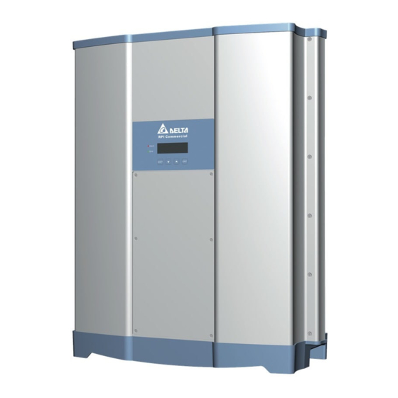
- Page 1 Installation and operation manual RPI M50A_12s Solar Inverter United Kingdom Europe general...
- Page 3 Delta Energy Systems (Germany) GmbH Tscheulinstraße 21 79331 Teningen Germany Authorized representative for this product in the EU: Delta Electronics (Netherlands) B.V.; Zandsteen 15, 2132 MZ Hoofddorp, NL Installation and Operation Manual for Inverter RPI M50A_12s V1 EU EN 2017-03-09...
-
Page 4: Table Of Contents
3 Table of Contents Table of Contents 1. About This Manual ............7 Purpose of This Manual . - Page 5 3 Table of Contents 5.11 External power-off ............40 5.12 Using external grid and system protection .
- Page 6 3 Table of Contents 8.4.5 DC Injection ............96 8.4.6 Dry contacts .
-
Page 7: About This Manual
WARNING Delta Energy Systems is not responsible for damage resulting from failure to follow the safety and operating instructions set out Indicates a dangerous situation that can lead to death or in this manual. -
Page 8: Writing And Labeling Conventions
1 About This Manual Writing and labeling conventions Some sections in this manual are specially labeled. Labeling of work instructions Work instructions that must be performed in a specific sequence are numbered accordingly. Numbered sequences of work steps must always be performed in the specified sequence. First step →... -
Page 9: Basic Safety Instructions
Therefore, always carry out the following steps before working on the inverter: ● All repair work on the inverter must be carried out by Delta Energy Systems. Otherwise, the warranty will be void. Turn the AC/DC disconnector to the OFF position. -
Page 10: Intended Purpose
3 Intended purpose Intended purpose The inverter may only be used for the specified intended pur- pose. The intended purpose of the inverter is defined as follows: ● Use in stationary solar systems connected to the public grid, for converting DC voltage generated by the solar modules in the solar system into AC voltage that is fed into the public grid. -
Page 11: Product Overview
4 Product overview Product overview Scope of delivery Part Quantity Description Part Quantity Description China Aviation Optical-Electrical Technology Co. PVE5T125KE36 Inverter AC plug 1 set with 3 sealing rings Sealing rings for Mounting plate AC plug Multi-Contact MC4-plug for DC + (32.0017P0001-UR for 4/6 mm To ground the inverter housing;... -
Page 12: Overview Of Components And Connections
4 Product overview Overview of components and connections Fig. 4.1: Overview of components and connections 1 Display, buttons, and LED See “4.3 Display, buttons, status LEDs”, page 13 See “4.4 String fuses”, page 14 and “4.5 Surge protection 2 Fuse box with string fuses and overvoltage conductors devices”, page 15 3 Air inlets See “4.6 Air inlets, air outlets and fans”, page 15... -
Page 13: Display, Buttons, Status Leds
4 Product overview Display, buttons, status LEDs Fig. 4.2: Overview of display, buttons, and LEDs Label Designation LEDs Grid Green LED; lights up when the inverter is supplying power to the grid. Alarm Red LED; displays a warning, an error or a fault. lArm Buttons Exit the current menu. -
Page 14: String Fuses
4 Product overview String fuses Fig. 4.4: Assignment of the string fuses to the DC inputs The inverter has string fuses on the DC side. Fig. 4.5: The inverter uses Littlefuse string fuses Fig. 4.3: Position of the string fuses on the inverter Type Manufacturer Littelfuse... -
Page 15: Surge Protection Devices
4 Product overview Surge protection devices Air inlets, air outlets and fans Fig. 4.8: Air inlets are located at the top of the left and right Fig. 4.6: Position of the surge protection devices on the sides inverter Fig. 4.9: Position of the fans and air outlet on the inverter Ambient air is sucked into the air inlets by the fans, passed Fig. -
Page 16: Electrical Connections
4 Product overview Electrical connections 4.7.1 Overview Fig. 4.10: Overview of electrical connections Component/Connection Label on the inverter Description Further information is provided in Grounding connection “4.7.2 Grounding connection”, page 17 Further information is provided in AC/DC disconnector DISCONN. AC/DC “4.7.3 AC/DC disconnector”, page 17 Further information is provided in AC connection... -
Page 17: Grounding Connection
4 Product overview 4.7.2 Grounding connection 4.7.3 AC/DC disconnector Fig. 4.11: Position of the grounding connection on the inverter Fig. 4.12: Position of the AC/DC disconnector on the inverter The inverter housing can be grounded via the grounding connec- tion. M6 screw, spring washer, washer, and toothed lock washer are already mounted on the inverter. -
Page 18: Ac Connection (Ac Output)
4 Product overview 4.7.5 DC connection (DC INPUT) 4.7.4 AC connection (AC OUTPUT) Fig. 4.14: Position of the DC connections on the inverter Fig. 4.13: Position of the AC connection on the inverter The solar modules are connected to the DC connections. The inverter is connected to the public grid via the AC connec- tion. -
Page 19: Communication Port 1
4 Product overview 4.7.6 Communication port 1 4.7.7 Communication port 2 Fig. 4.15: Position of communication connection 1 on the Fig. 4.16: Position of communication connection 2 on the inverter inverter Available connections: Communication connection 2 is not used on this inverter. Connection Connection type 2x RS485 (DATA+ and DATA–) -
Page 20: Information On The Type Plate
4 Product overview Information on the Type Plate Information on the Type Plate Description Danger to life through electric shock Potentially fatal voltage is present inside the inverter during operation and this voltage is still present 10 seconds after disconnection of the power supply. 10 seconds Only the fuse box may be opened. -
Page 21: Planning Installation
5 Planning installation Planning installation This chapter only describes planning of the installation work. The executionof the installation work and the associated dangers are described in chapter “6. Installation”, page 45. Installation location ✘ ✘ ✔ ► Attach the inverter so that the information on the display can be read and the buttons can be operated without any problems. -
Page 22: Outdoor Installations
5 Planning installation Outdoor installations ► The inverter has a protection degree of IP65 and can be installed indoors and outdoors. Despite this, the inverter should be protected by a roof against direct solar irradiation, rain and snow. For example, the power of the inverter will be reduced if it is too heavily heated by solar irradiation. -
Page 23: Installation Clearances And Air Circulation
5 Planning installation Installation clearances and air circula- tion >30 cm >30 cm >30 cm Fig. 5.1.: Installation clearances and air circulation I ► Ensure sufficient air circulation. Warm air must be able to escape from below. ► Leave enough space around each inverter. ►... - Page 24 5 Planning installation Fig. 5.1: Air flow around solar inverters Installation and Operation Manual for Inverter RPI M50A_12s V1 EU EN 2017-03-09...
-
Page 25: Characteristic Curves
5 Planning installation Characteristic curves S [VA] = P [W] 800 V 600 V P/P n (P n = 50 kW) 520 V 115% 110% 105% 100% Ambient temperatures [°C] Fig. 5.2: Characteristic curve "Power reduction depending on the ambient temperature, cos φ = 1.0" (derating) Installation and Operation Manual for Inverter RPI M50A_12s V1 EU EN 2017-03-09... - Page 26 5 Planning installation S [VA] P [W] 800 V 800 V 600 V 600 V P/P n (P n = 50 kW) 520 V 520 V 115% 110% 105% Ambient temperatures [°C] Fig. 5.3: Characteristic curve "Power reduction depending on the ambient temperature, cos φ = 0.95" (derating) Installation and Operation Manual for Inverter RPI M50A_12s V1 EU EN 2017-03-09...
- Page 27 5 Planning installation S [VA] P [W] 800 V 800 V 600 V 600 V P/P n (P n = 50 kW) 520 V 520 V 115% 110% 105% 100% Ambient temperatures [°C] Fig. 5.4: Characteristic curve "Power reduction depending on the ambient temperature, cos φ = 0.90" (derating) Installation and Operation Manual for Inverter RPI M50A_12s V1 EU EN 2017-03-09...
- Page 28 5 Planning installation 800 V 600 V Efficiency 520 V 100% Power [kW] Fig. 5.5: Efficiency curve Installation and Operation Manual for Inverter RPI M50A_12s V1 EU EN 2017-03-09...
-
Page 29: Dimensions
5 Planning installation Dimensions Fig. 5.6: Dimensions Installation and Operation Manual for Inverter RPI M50A_12s V1 EU EN 2017-03-09... -
Page 30: Ac Connection (Grid)
DIN VDE 0100-712. ● Loss of power in the cable Possible error events were assessed by Delta in accordance with the current installation standards. The assessments showed that ► Always follow the installation regulations for AC cables appli- no hazards arise from operating the inverter in combination with cable in your country. -
Page 31: Permissible Grounding Systems
5 Planning installation 5.6.6 Permissible grounding systems DC connection (solar modules) Grounding system TN-S TN-C TN-C-S TT NOTICE Allowed Incorrectly dimensioned solar system. An solar system of the wrong size may cause 5.6.7 Requirements for the grid voltage damage to the inverter. ►... -
Page 32: Symmetric And Asymmetric Configuration Of The Dc Inputs
5 Planning installation 5.7.1 Symmetric and asymmetric configuration Symmetrical design of the DC inputs The inverter has a separate MPP tracker for each DC input (DC1 Input Current and DC2). The two MPP trackers work independently, i.e. the optimum I max working point is set separately for DC1 and DC2. -
Page 33: Separately Connected And Parallel-Connected Dc Inputs
5 Planning installation 5.7.2 Separately connected and parallel-con- nected DC inputs The inverter can be operated with separately connected and parallel-connected DC inputs. Separately connected DC inputs PV array DC wiring Fig. 5.10: Separately connected DC inputs The module strings for DC1 and DC2 are connected sepa- rately. -
Page 34: Parallel-Connected Dc Inputs
5 Planning installation 5.7.3 Parallel-connected DC inputs PV array DC wiring Distribution box – Fig. 5.11: Parallel-connected DC inputs The module strings are combined at a distribution box and the DC cable is then connected to DC1 and DC2. MPP tracker 1 regulates all module strings, MPP tracker 2 is not used. -
Page 35: Connecting Solar Modules That Are Not Grounded
5 Planning installation 5.7.4 Connecting solar modules that are not grounded The DC inputs can be connected to the DC inputs separately or in parallel when using non-grounded solar modules. PV array AC wiring 3P4W 3P3W 1 - L1 1 - L1 2 - L2 2 - L2 3 - L3... -
Page 36: Connecting Grounded Solar Modules
► The insulation monitoring can be set on the inverter display after commissioning, see “8.4.2 Insulation”, page 84. PV array Utility parallel DC inputs 3-phase, 230/400 V ONLY star or delta connection Isolated Isolated DC wiring transformer transformer Distribution Box... -
Page 37: Connecting The Dc Strings To The Dc Inputs
5 Planning installation 5.7.6 Connecting the DC strings to the DC inputs ► Check the polarity of the DC voltage at the DC strings before connecting the solar modules to the inverter. ► Connect the negative pole of the solar modules to DC–, connect the positive pole to DC+. -
Page 38: Cable Requirements
5 Planning installation 5.7.7 Cable requirements The DC plugs for all DC connections are supplied with the inverter. If you want to order more or need a different size, see the infor- mation in the following table. DC connections on the inverter DC plugs for DC cables MultiContact 32.0010P0001-UR... -
Page 39: Connecting A Data Logger
5 Planning installation Connecting a data logger Connecting an external alarm unit The inverter can be connected to a data logger via RS485, e.g. The inverter has two multifunction relays allowing connection of for monitoring the PV system or changing the inverter settings. an acoustic or visual alarm unit to each. -
Page 40: Connecting A Ripple Control Receiver
5 Planning installation 5.10 Connecting a ripple control receiver 5.11 External power-off An external ripple control receiver can be connected to the digital The inverter has a multifunction relay allowing an external shut- inputs. down of the inverter to be triggered. Pin assignments Pin assignments Designa-... -
Page 41: Using External Grid And System Protection
For changing the inverter Delta Service Software settings This inverter satisfies the requirements of (2) when the following firmware versions are installed: DSP ≥ 1.30 / The Delta Service Software can be downloaded from www. RED ≥ 1.20 / COMM ≥ 1.10. External grid and system protection solar-inverter.com. is not necessary for inverters with these firmware versions. Cable requirements Bell wire. -
Page 42: Tools And Materials Required
5 Planning installation 5.14 Tools and materials required This sections lists the necessary tools and materials not included in the scope of delivery. 5.14.1 For mounting the inverter Part Quantity Description The mounting plate must be attached using 6 or 12 M6 screws. Additional mounting materials may be required depending on the installation position of the inverter (e.g. -
Page 43: For Connecting To The Solar Modules (Dc)
Shielded twisted-pair cable (CAT5 or CAT6) with solid conductors Cable ● Cable diameter: 5 mm ● Wire cross-section: 1 mm For connecting to SOLIVIA Monitor, the Internet-based monitoring system from Delta. SOLIVIA Gateway M1 G2 Installation and Operation Manual for Inverter RPI M50A_12s V1 EU EN 2017-03-09... -
Page 44: For Connecting A Pc
Part Quantity Description USB/RS485 adapter Standard USB/RS485 adapter 2-core cable Bell wire. Both ends open. The Delta Service Software can be downloaded from www.solar-inverter. Delta Service Software com. 5.14.7 Other parts Part Quantity Description Observe the local regulations regarding the application of warning labels. -
Page 45: Installation
6 Installation Installation WARNING Heavy weight ► Read chapter “5. Planning installation”, The inverter is very heavy. page 21 and this chapter in full before you ► The inverter must be lifted and carried by start installation. at least 3 people or using appropriate lifting gear. -
Page 46: Mounting The Inverter
6 Installation Mounting the inverter Attach the mounting plate to the wall / the mounting system with 6 or 12 M6 screws. Mount the inverter on the mounting plate. Installation and Operation Manual for Inverter RPI M50A_12s V1 EU EN 2017-03-09... - Page 47 6 Installation Check that the inverter is correctly mounted on the mount- ing plate. Check that the lower end of the inverter is correctly posi- tioned on the wall / mounting system. Installation and Operation Manual for Inverter RPI M50A_12s V1 EU EN 2017-03-09...
- Page 48 6 Installation Check that the inverter is correctly mounted on the mount- ing plate. Installation and Operation Manual for Inverter RPI M50A_12s V1 EU EN 2017-03-09...
-
Page 49: Grounding The Inverter Housing
6 Installation Grounding the inverter housing DANGER Electrical shock ► Always observe the local regulations relating to grounding cable requirements. ► To increase the safety of the system, always ground the inverter housing even when this is not required by the local regulations. ►... -
Page 50: Connecting The Communication Card
6 Installation Connecting the communication card NOTICE Water penetration. ► Store all sealing caps removed during instal- lation for later use (e.g. transport or storage). The connections for RS485, the dry contacts, the digital inputs and the external shutdown (EPO) are all on the communication card. -
Page 51: Initial Steps
6 Installation 6.5.2 Initial steps Unscrew the cable gland of the communication connection and remove the cable gland and seal. Unscrew and carefully pull out the cover. The communica- tion card is screwed to the cover. Installation and Operation Manual for Inverter RPI M50A_12s V1 EU EN 2017-03-09... - Page 52 6 Installation Remove the same number of rubber plugs from the seal corresponding to the number of cables to be connected. Do not remove the rubber plugs from the unused seal feed- throughs. Pull the cable through the cable gland and seal. Installation and Operation Manual for Inverter RPI M50A_12s V1 EU EN 2017-03-09...
-
Page 53: Connecting A Data Logger Via Rs485
► Do not use GND and VCC. ► If the cable shield is used for providing Connection to a Delta SOLIVIA Gateway M1 G2 lightning protection then the housing of only Individual wires are connected at the inverter and an RJ45 plug is one inverter in the RS485 chain should be used at the gateway. - Page 54 6 Installation Wiring diagram for multiple inverters ► If the data logger does not have an integrated RS485 termi- nation resistor, switch on the RS485 termination resistor on the first inverter. ► Set a different inverter ID at each inverter during commis- sioning of the inverters.
-
Page 55: Wiring For A Single Inverter
6 Installation 6.5.3.1 Wiring for a single inverter Connect the DATA+ wire to terminal 5 and the DATA– wire to terminal 6. Put the DIP switch for the RS485 termination resistor (DIP 2) in the ON position. Installation and Operation Manual for Inverter RPI M50A_12s V1 EU EN 2017-03-09... -
Page 56: Wiring For Multiple Inverters
6 Installation 6.5.3.2 Wiring for multiple inverters Data logger On the cable coming from the data logger: Connect the DATA+ wire to terminal 5 and the DATA– wire to terminal 6. On the cable going to the second inverter: Connect the DATA+ wire to terminal 3 and the DATA–... - Page 57 6 Installation Data logger On the cable coming from the previous inverter: Connect the DATA+ wire to terminal 5 and the DATA– wire to termi- nal 6. On the cable going to the next inverter: Connect the DATA+ wire to terminal 3 and the DATA– wire to terminal 4. Put the DIP switch for the RS485 termination resistor (DIP 2) in the OFF position.
- Page 58 6 Installation Data logger Connect the DATA+ wire to terminal 5 and the DATA– wire to terminal 6 Put the DIP switch for the RS485 termination resistor (DIP 2) in the ON position. Installation and Operation Manual for Inverter RPI M50A_12s V1 EU EN 2017-03-09...
-
Page 59: Connecting An External Alarm Unit
6 Installation 6.5.4 Connecting an external alarm unit Cable and wiring requirements ● Shielded twisted-pair cable with solid conductors (CAT 5 or CAT 6. ● Cable diameter: 5 mm ● Wire cross-section: 1 mm ► Lay the cable with a suitable clearance to the AC and DC cables to prevent interference in the data connection. -
Page 60: Wiring For A Single Alarm Unit With An Internal
6 Installation 6.5.4.2 Wiring for a single alarm unit with an internal 12 V power supply Connection examples RS485 terminal block Dry contacts plug RS485 terminal block Dry contacts plug Strobe light Strobe light Fig. 6.16: Connection example 1: 1 dry contact with an internal Fig. -
Page 61: Wiring For Two Alarm Units With An Internal
6 Installation 6.5.4.3 Wiring for two alarm units with an internal 12 V power supply Connection examples RS485 terminal block Dry contacts plug RS485 terminal block Dry contacts plug Strobe light Buzzer Strobe light Buzzer Strobe light Strobe light Buzzer Buzzer Fig. -
Page 62: Connecting Digital Inputs And External Power-Off (Epo)
6 Installation 6.5.5 Connecting digital inputs and external Connecting a ripple control receiver power-off (EPO) Power limiting to: Short circuit Pin assignments Terminals V1 and K1 Terminals V1 and K2 Designa- Sort-circuit Assigned action tion Terminals V1 and K3 – –... - Page 63 6 Installation The colors of the wires in the connection example correspond to a standard CAT5 cable and may differ in other cables. The wire colors have no effect on the function of the wiring. Connect the wires according to the desired connection diagram.
-
Page 64: Final Work
6 Installation 6.5.6 Final work Fit the communication card cover and screw in place. Fit the seal and cable gland and screw the cable gland tight. Installation and Operation Manual for Inverter RPI M50A_12s V1 EU EN 2017-03-09... -
Page 65: Connecting To The Grid (Ac)
6 Installation Connecting to the grid (AC) The inverter can be connected to 3-phase grids without neutral conductors (3P3W, 3 phases + PE) and 3-phase grids with neutral conductors (3P4W, 3 phases + N + PE). ► If makes no difference which individual wire of the AC cable is connected to which contact. - Page 66 6 Installation Installation and Operation Manual for Inverter RPI M50A_12s V1 EU EN 2017-03-09...
- Page 67 6 Installation Remove the insulation from the cable and wires. Do not twist the wire ends because this reduces the contact sur- face area with the wire end sleeves. 22 ± 2 mm Wire end sleeves must be used with some wire cross-sec- tions, see the following table.
- Page 68 6 Installation Assemble the AC plug. 5.4 ... 7.4 Nm 5.4 ... 7.4 Nm D... 5.4 ... 7.4 Nm Installation and Operation Manual for Inverter RPI M50A_12s V1 EU EN 2017-03-09...
- Page 69 6 Installation Turn the AC/DC disconnector to the OFF position. Remove the sealing cap from the AC connection and store in a safe place. Plug the AC plug into the AC connection on the inverter and twist tight. Fasten the AC cable with a strain relief element. 10.
-
Page 70: Connecting Solar Modules (Dc)
6 Installation Connecting solar modules (DC) DANGER Electrical shock Potentially fatal voltage is present at the invert- er's DC connections. When light falls on the solar modules, they immediately start to generate electricity. This also happens when light does not fall directly on the solar modules. - Page 71 6 Installation Remove the sealing caps from the DC connections and store in a safe place. Do not remove the sealing caps from the unused DC con- nections. Plug the DC plugs with the DC cables into the DC connec- tions on the inverter.
-
Page 72: Attaching Warning Labels To The Inverter
6 Installation Attaching warning labels to the inverter Connecting a PC via RS485 ► Attach all necessary warning labels to the inverter. Always Inverter USB/RS485 adapter follow the local regulations. Some examples of warning labels are listed below. Do not work on this equipment until it is located WARNING from both mains and on site generation supplies. -
Page 73: Commissioning
7 Commissioning Commissioning To perform the commissioning steps described in this section the inverter must be supplied with either AC power (grid) or DC power at both DC inputs (solar modules). Turn the AC/DC disconnector to the ON position. S e l e c t l a n g u a g e Use the buttons to select the English language and then press the E n g l i s h... - Page 74 7 Commissioning Check that the correct inverter ID is set. A r e y o u s u r e t o s e t I D : buttons to select the Yes If the correct inverter ID is selected, use the entry and the press the button.
-
Page 75: Settings
8 Settings Settings Overview 8.2 "Inverter info." menu area (current settings) ......... . . 76 8.3 "General settings"... -
Page 76: Inverter Info." Menu Area (Current Settings)
8 Settings "Inverter info." menu area (current set- tings) Overview This function allows you to display the current inverter settings. Setting options None. Menu item path Main menu > Inverter Info. Displaying the inverter information If the default information is displayed, press any button to open the main menu. 1 0 . - Page 77 8 Settings Displayed information Description How can I change this setting See “8.4.9 AC connection”, page 102 for a AC connection: 3P4W A C c o n n e c t i o n : 3 P 4 W detailed description and how to change the M a x .
-
Page 78: General Settings" Menu Area
8 Settings "General settings" menu area 8.3.1 Language Overview This function allows you to set the display language. Setting options Parameter Description Setting range German | English | Spanish | French | The display language. Language Italian | Dutch Menu item path Main menu >... -
Page 79: Date And Time
8 Settings 8.3.2 Date and Time Overview This function allows you to set the date and time. The date and time must be set correctly for exact calculations of the statistics in the inverter or in a monitoring system. Setting options Parameter Description Setting range... -
Page 80: Baud Rate
8 Settings 8.3.3 Baud rate Overview This function allows you to set the RS485 baud rate. If multiple inverters are connected via RS485 then the same baud rate must be set at every inverter. Setting options Parameter Description Setting range Baud rate for RS485 Baud rate 9600 | 19200 | 38400... -
Page 81: Protocol
Setting options Parameter Description Setting range Type of RS485 protocol used for RS485 communi- Prot. Delta/Solivia | Prot. Sunspec cation. Menu item path Main Menu > General settings > Protocol Setting the RS485 protocol If the default information is displayed, press any button to open the main menu. -
Page 82: Test Menu
8 Settings 8.3.5 Test menu See “11.2 Checking the fans”, page 136 for a description Installation and Operation Manual for Inverter RPI M50A_12s V1 EU EN 2017-03-09... -
Page 83: Installation Settings" Menu Area
8 Settings "Installation settings" menu area This menu area is password-protected because the settings in this menu area affect the energy production of the inverter. ► Exercise extra care with all settings in this menu area. 8.4.1 Inverter ID Overview This function allows you to set the inverter ID. -
Page 84: Insulation
Changing these parameter settings can invalidate the type approval of the unit. Change this setting only after consultation with Delta customer service. Overview This function allows you to set the insulation mode and insulation resistance. - Page 85 8 Settings M o d e : O N Use the buttons to select the Resistance entry and then press the R e s i s t a n c e : 1 1 0 0 k Ω button. The currently set value is displayed after the entry. 1 5 0 k Ω...
-
Page 86: Country
A c t i v e / R e a c t i v e P w r F R T Enter the password provided by Delta customer service. W a r n i n g : A d j . w o u l d a f f e c t Use the buttons to set the individual numerals. -
Page 87: Grid Settings
Delta customer service. 8.4.4.1 Overview To change this setting, you need a special pass- word provided by Delta customer service. You can find the contact information on the back of this document. This menu area is used to define the behavior of the inverter in the case of faults in the public grid. -
Page 88: Voltage Protection
Delta customer service. Overview To change this setting, you need a special password provided by Delta customer service. You can find the contact information on the back of this document. This function allows you to defined the behavior of the inverter in the case of grid overvoltage or undervoltage. - Page 89 A c t i v e / R e a c t i v e P w r F R T W a r n i n g : Enter the password provided by Delta customer service. Use the buttons to A d j . w o u l d a f f e c t set the individual numerals.
- Page 90 8 Settings V o l t a g e P r o t e c t i o n Use the buttons to select the Voltage Protection entry and then press F r e q . P r o t e c t i o n button.
-
Page 91: Frequency Protection
Delta customer service. Overview To change this setting, you need a special pass- word provided by Delta customer service. You can find the contact information on the back of this document. This function allows you to defined the behavior of the inverter in the case of grid overfrequency or underfrequency. - Page 92 A c t i v e / R e a c t i v e P w r F R T Enter the password provided by Delta customer service. W a r n i n g : A d j . w o u l d a f f e c t Use the buttons to set the individual numerals.
-
Page 93: Reconnection Time
A c t i v e / R e a c t i v e P w r F R T Enter the password provided by Delta customer service. W a r n i n g : A d j . w o u l d a f f e c t Use the buttons to set the individual numerals. - Page 94 8 Settings Use the buttons to configure the value and then press the button. Installation and Operation Manual for Inverter RPI M50A_12s V1 EU EN 2017-03-09...
-
Page 95: P Ramp Up
A c t i v e / R e a c t i v e P w r F R T Enter the password provided by Delta customer service. W a r n i n g : A d j . w o u l d a f f e c t Use the buttons to set the individual numerals. -
Page 96: Dc Injection
A c t i v e / R e a c t i v e P w r F R T Enter the password provided by Delta customer service. W a r n i n g : A d j . w o u l d a f f e c t Use the buttons to set the individual numerals. - Page 97 8 Settings Setting the mode M o d e : Use the buttons to select the Mode entry and then press the button. T r i p V a l u e : 1 . 0 0 A → The shape of the arrow changes , the value can be changed.
-
Page 98: Dry Contacts
A c t i v e / R e a c t i v e P w r F R T Enter the password provided by Delta customer service. W a r n i n g : Use the buttons to set the individual numerals. - Page 99 8 Settings D r y C o n t . A D i s a b l e Use the buttons to select a dry contact and then press the button. D r y C o n t . B D i s a b l e D i s a b l e Use the...
-
Page 100: Rcmu (Integrated Residual Current Monitoring Unit)
A c t i v e / R e a c t i v e P w r F R T Enter the password provided by Delta customer service. W a r n i n g : A d j . w o u l d a f f e c t Use the buttons to set the individual numerals. -
Page 101: Epo (External Power-Off )
8 Settings 8.4.8 EPO (External power-off ) Overview This function allows you to define the relay contacts for the exter- nal power-off (EPO) as being normally closed or normally open contacts. Setting options Parameter Description Setting range Defines how the relay functions for the external Normal Open | Normal Closed power-off (EPO). -
Page 102: Ac Connection
8 Settings 8.4.9 AC connection Overview The inverter is configured by default for an AC connection with 3-phases and a neutral conductor (3P4W). If you wish to connect the inverter without a neutral conductor then you must set the AC connection type to 3P3W after commissioning. -
Page 103: Anti-Islanding
A c t i v e / R e a c t i v e P w r F R T Enter the password provided by Delta customer service. W a r n i n g : A d j . w o u l d a f f e c t Use the buttons to set the individual numerals. -
Page 104: Max. Power (Maximum Active Power)
Changing these parameter settings can invalidate the type approval of the unit. Change this setting only after consultation with Delta customer service. Overview This function allows you to set the maximum active power fed into the grid. -
Page 105: Loading The Factory Settings
A c t i v e / R e a c t i v e P w r F R T Enter the password provided by Delta customer service. W a r n i n g : A d j . w o u l d a f f e c t Use the buttons to set the individual numerals. -
Page 106: Active/Reactive Power" Menu Area
Changing these parameter settings can invalidate the type approval of the unit. Change this setting only after consultation with Delta customer service. Overview This function allows you to additionally limit the active power. The active power is specified as a percentage of the value set in the Max. - Page 107 8 Settings A c t i v e P o w e r C t r l Use the buttons to select the Active Power Ctrl entry and then press the R e a c t i v e P o w e r C t r l button.
-
Page 108: Regulating The Active Power Via The Grid Frequency
Changing these parameter settings can invalidate the type approval of the unit. Change this setting only after consultation with Delta customer service. Overview This function allows you to regulate the active power fed into the grid via the grid frequency. - Page 109 8 Settings Setting options Parameter Description Setting range Switch the function on and off. Mode ON | OFF F Start The grid frequency above which the active power being fed is 50.00 .. 55.00 Hz reduced. The grid frequency below which the active power being fed is F Restart 50.00 ..
- Page 110 8 Settings Setting the mode M o d e : Use the buttons to select the Mode entry and then press the button. F S t a r t : 5 0 . 2 0 H z → The shape of the arrow changes , the value can be changed.
-
Page 111: P (V) (Regulating The Active Power Via The Grid Voltage)
Changing these parameter settings can invalidate the type approval of the unit. Change this setting only after consultation with Delta customer service. Overview This function allows you to regulate the active power fed into the grid via the grid voltage. - Page 112 8 Settings Setting the mode M o d u s : E I N Use the buttons to select the Mode entry and then press the button. P l o c k - i n : 2 0 % → The shape of the arrow changes , the value can be changed.
-
Page 113: Constant Cos Phi (Cos Φ)
8.5.4 Constant cos phi (cos φ) These parameters are set according to the requirements of the selected country. Changing these parameter settings can invalidate the type approval of the unit. Change this setting only after consultation with Delta customer service. Overview This function allows you to set a constant cos φ. Setting options Parameter... - Page 114 8 Settings Setting the mode M o d e : Use the buttons to select the Mode entry and then press the button. C o s p h i : I n d 1 . 0 0 → The shape of the arrow changes , the value can be changed.
-
Page 115: Cos Phi (P) (Regulate Cos Phi Via Active Power)
These parameters are set according to the requirements of the selected country. Changing these parameter settings can invalidate the type approval of the unit. Change this setting only after consultation with Delta customer service. Overview This function allows you to regulate cos phi (cos φ) via the via active power. cos φ... - Page 116 8 Settings I n v e r t e r I n f o . G e n e r a l S e t t i n g s Use the buttons to select the Active/Reactive Pwr entry and then press I n s t a l l S e t t i n g s button.
-
Page 117: Constant Q (Constant Reactive Power)
These parameters are set according to the requirements of the selected country. Changing these parameter settings can invalidate the type approval of the unit. Change this setting only after consultation with Delta customer service. Overview This function allows you to set constant reactive power. Setting options... - Page 118 8 Settings Setting the mode M o d e : Use the buttons to select the Mode entry and then press the button. F i x Q : I n d 9 0 % → The shape of the arrow changes , the value can be changed.
-
Page 119: Q (V) - Regulating Reactive Power Via Voltage
Changing these parameter settings can invalidate the type approval of the unit. Change this setting only after consultation with Delta customer service. Overview This function allows you to regulate the reactive power via the voltage. - Page 120 8 Settings Setting options Parameter Description Setting range Switch the function on and off. Mode ON | OFF The lower voltage limit for feeding inductive reactive power. 220.0 .. 292.0 V The upper voltage limit for feeding inductive reactive power. 220.0 ..
- Page 121 8 Settings Setting the mode M o d e : O F F Use the buttons to select the Mode entry and then press the button. V 1 s : 2 4 8 . 4 V → The shape of the arrow changes , the value can be changed.
-
Page 122: Frt (Fault Ride Through)
Delta customer service. Overview To change this setting, you need a special pass- word provided by Delta customer service. You can find the contact information on the back of this document. This function allows you to defined the behavior of the inverter in the case of short-term grid voltage dropouts. - Page 123 8 Settings Calling up the menu item If the default information is displayed, press any button to open the main menu. 1 0 . S e p 2 0 1 4 1 5 : 3 2 S t a t u s : O n G r i d Otherwise, press the button repeatedly until the main menu is displayed.
-
Page 124: Measurements And Statistics
9 Measurements and statistics Measurements and statistics The following information is available: Type of information Description Measurements Current data for various parameters Energy log Information on the energy generated over the entire usage period of the inverter Event log A list of major events, e.g. warning messages, faults, parameter changes etc., with date and time. Inverter Information on general settings, grid settings, active power and reactive power monitoring, firmware information... -
Page 125: Energy Log
9 Measurements and statistics Energy log Overview This menu shows the energy yields for various time periods. Setting options The displayed information cannot be edited. Menu item path Main menu > Energy log Displaying the energy log If the default information is displayed, press any button to open the main menu. 1 0 . -
Page 126: Event Log
9 Measurements and statistics Event log The event log contains error event messages and a grid report. 9.3.1 Error events Overview This menu shows a list with the last 30 error events. Setting options The list can be deleted. Menu item path Main Menu >... -
Page 127: Grid Report
9 Measurements and statistics 1 . 2 3 / 0 2 / 2 0 1 6 1 7 : 2 0 Press and hold the buttons simultaneously for at least 5 seconds. A C F r e q H i g h →... - Page 128 9 Measurements and statistics If the default information is displayed, press any button to open the main menu. 1 0 . S e p 2 0 1 4 1 5 : 3 2 S t a t u s : O n G r i d Otherwise, press the button repeatedly until the main menu is displayed.
-
Page 129: Error Events And Troubleshooting
The inverter is very heavy. ► The inverter must be lifted and carried by at least 3 people or using appropriate lifting gear. Only Delta Customer Service is permitted to perform repair work and replace inverter compo- nents. Exceptions: ► Replacing the fans. -
Page 130: Error
10 Error events and troubleshooting 10.1 Error Number Message Possible cause Correction suggestions Mains grid frequency lies above the OFR setting Check the grid frequency on the inverter display. (overfrequency detection). AC Freq High (AC Freq High) Check the country setting on the inverter dis- Incorrect country setting. -
Page 131: Warnings
10 Error events and troubleshooting 10.2 Warnings Number Message Possible cause Correction suggestions Check the DC input voltage at DC1 on the The DC input voltage at DC1 is less than the Solar1 Low inverter display. (Solar1 Low) minimum permissible DC input voltage. There may be insufficient solar irradiation. -
Page 132: Faults
10 Error events and troubleshooting 10.3 Faults Number Message Possible cause Correction suggestions F36, F37, Overvoltage during operation. Contact Delta Customer Service. AC Current High F38, F39, (AC Current High) Internal error. Contact Delta Customer Service. F40, F41 Incomplete independent or parallel configuration Check the input connections. - Page 133 F18, HW Red ADC1, required DC voltage. There may be insufficient solar irradiation. HW Red ADC2 Internal error. Contact Delta Customer Service. HW ZC Fail Internal error. Contact Delta Customer Service. (HW ZC Fail) RCMU Fail Internal error. Contact Delta Customer Service.
-
Page 134: Maintenance
11 Maintenance Maintenance WARNING Heavy weight DANGER The inverter is very heavy. ► The inverter must be lifted and carried by Electrical shock at least 3 people or using appropriate lifting Potentially fatal voltage is applied to the inverter gear. during operation. -
Page 135: Periodic Maintenance
11 Maintenance 11.1 Periodic maintenance Perform the following checks every 6 months. ● Check the string fuses. Measure the current using a current transformer. ● Check the fans for soiling and clean if necessary. ● Test the fans, see “11.2 Checking the fans”, page 136. ●... -
Page 136: Checking The Fans
11 Maintenance 11.2 Checking the fans The inverter must be supplied with DC voltage in order to be able to perform the fan test. Menu item path Main menu > General settings > Test Menu Performing the fan test If the default information is displayed, press any button to open the main menu. 1 0 . - Page 137 11 Maintenance The list shows the fans that are defective. Result when no fans are defective. F a i l e d F a n : E m p t y Result when one fan is defective. F a i l e d F a n : E x t F a n 1 Installation and Operation Manual for Inverter RPI M50A_12s V1 EU EN 2017-03-09...
-
Page 138: Replacing/Cleaning The Fans
11 Maintenance 11.3 Replacing/cleaning the fans DANGER Electrical shock Potentially lethal voltage is still present on the in- ner electrical components of the inverter after the AC/DC disconnector has been opened. Turn the AC/DC disconnector to the OFF position. Disconnect the inverter from all AC and DC voltage sources and make sure that none of the connections can be accidentally restored. - Page 139 11 Maintenance Unscrew and unplug the AC plug. Use the mounting tool to release the DC plugs and then pull them out. Wait for at least 10 seconds until the internal capacitors have discharged. Unscrew and carefully pull out the fan block. Installation and Operation Manual for Inverter RPI M50A_12s V1 EU EN 2017-03-09...
- Page 140 11 Maintenance Pull the plugs of the power supply cable out of the fan con- nectors. Installation and Operation Manual for Inverter RPI M50A_12s V1 EU EN 2017-03-09...
- Page 141 11 Maintenance 10. Clean the fans with a compressed air cleaner or a stiff paintbrush. 11. Insert the plugs of the power supply cable into the fan con- nectors. CLICK Installation and Operation Manual for Inverter RPI M50A_12s V1 EU EN 2017-03-09...
- Page 142 11 Maintenance 12. Insert the fan block and screw in place. Installation and Operation Manual for Inverter RPI M50A_12s V1 EU EN 2017-03-09...
- Page 143 11 Maintenance 13. Plug in the DC plugs. 14. Plug in the AC plug and screw tight. 15. Turn the AC/DC disconnector to the ON position. Installation and Operation Manual for Inverter RPI M50A_12s V1 EU EN 2017-03-09...
-
Page 144: Cleaning The Air Inlets
11 Maintenance 11.4 Cleaning the air inlets The screws on the filter housing are very small and can easily fall down. You should therefore use a magnetic screwdriver. ∫ Unscrew and remove the air inlet covers. Installation and Operation Manual for Inverter RPI M50A_12s V1 EU EN 2017-03-09... - Page 145 11 Maintenance Clean the filters with a compressed air cleaner or a stiff paintbrush. Fit the air inlet covers and screw in place. Installation and Operation Manual for Inverter RPI M50A_12s V1 EU EN 2017-03-09...
-
Page 146: Replacing The Surge Protection Devices
Wait for at least 10 seconds until the internal capacitors have discharged. The surge protection devices are replaced as a block. You can obtain spare parts from Delta Customer Service. The contact information is provided on the last page of this document ∫... - Page 147 11 Maintenance Use the mounting tool to release the DC plugs and then pull them out. Unscrew and remove the fuse box cover. Installation and Operation Manual for Inverter RPI M50A_12s V1 EU EN 2017-03-09...
- Page 148 11 Maintenance Pull out both power cable plugs. Pull out the communication cable plug. Unscrew the 6 screws and lift out the block with the defective surge protection devices. Installation and Operation Manual for Inverter RPI M50A_12s V1 EU EN 2017-03-09...
- Page 149 11 Maintenance Fit the new block with the surge protection devices and screw in place using the 6 screws. Plug in the communication cable plug. Installation and Operation Manual for Inverter RPI M50A_12s V1 EU EN 2017-03-09...
- Page 150 11 Maintenance 10. Plug in both power cable plugs. CLICK The fuse box cover must sit correctly and prop- erly seal the fuse box in order to ensure an IP65 degree of protection. 11. Fit the fuse box cover and screw in place. Installation and Operation Manual for Inverter RPI M50A_12s V1 EU EN 2017-03-09...
- Page 151 11 Maintenance 12. Plug in the DC plugs. 13. Plug in the AC plug and screw tight. 14. Turn the AC/DC disconnector to the ON position. Installation and Operation Manual for Inverter RPI M50A_12s V1 EU EN 2017-03-09...
-
Page 152: Replacing String Fuses
11.6 Replacing string fuses Replace only with the string fuses specified in the table! Delta reserves the right to invalidate all warranty claims if other string fuses are used and this results in problems with the inverter or the instal- lation. - Page 153 11 Maintenance Unscrew and remove the fuse box cover. Localize the defective string fuse using a current transformer. Pull out the fuse holder of the defective string fuse using your fingers. Installation and Operation Manual for Inverter RPI M50A_12s V1 EU EN 2017-03-09...
- Page 154 11 Maintenance Replace the defective string fuse with a new string fuse. Insert the fuse holder of the new string fuse using your fingers. The fuse box cover must sit correctly and prop- erly seal the fuse box in order to ensure an IP65 degree of protection.
- Page 155 11 Maintenance 10. Plug in the DC plugs. 11. Plug in the AC plug and screw tight. 12. Turn the AC/DC disconnector to the ON position. Installation and Operation Manual for Inverter RPI M50A_12s V1 EU EN 2017-03-09...
-
Page 156: Decommissioning
12 Decommissioning Decommissioning DANGER Electrical shock Potentially fatal voltage is applied to the inverter during operation. When the inverter is discon- nected from all power sources, this voltage remains in the inverter for up to 10 seconds. Therefore, always carry out the following steps before working on the inverter: Turn the AC/DC disconnector to the OFF position. - Page 157 12 Decommissioning Turn the AC/DC disconnector to the OFF position. Disconnect the connection between the inverter and the solar modules (DC). Disconnect the connection between the inverter and the grid (AC). Use a voltmeter to check that the AC and DC connections are free of voltage.
- Page 158 12 Decommissioning Use the mounting tool to release the DC plugs and then pull them out. Seal the DC connections using the sealing caps Installation and Operation Manual for Inverter RPI M50A_12s V1 EU EN 2017-03-09...
- Page 159 12 Decommissioning Unscrew the cable gland of the communication connection and remove the cable gland and seal 10. Unscrew and carefully pull out the cover. The communica- tion card is screwed to the cover. Installation and Operation Manual for Inverter RPI M50A_12s V1 EU EN 2017-03-09...
- Page 160 12 Decommissioning 11. Remove the cable and re-insert the cover with the commu- nications card and screw tight. 12. Insert the rubber plug in the seal. Installation and Operation Manual for Inverter RPI M50A_12s V1 EU EN 2017-03-09...
- Page 161 12 Decommissioning 13. Fit the seal and cable gland and screw the cable gland tight. 14. Unscrew the grounding cable. 15. Refit the grounding screw, spring washer, washer and lock washer. Installation and Operation Manual for Inverter RPI M50A_12s V1 EU EN 2017-03-09...
- Page 162 12 Decommissioning 16. Unscrew the inverter from the wall or mounting system at both sides. 17. Lift the inverter off the mounting plate. Installation and Operation Manual for Inverter RPI M50A_12s V1 EU EN 2017-03-09...
- Page 163 12 Decommissioning 18. Place the inverter in the original box. The following steps are only necessary when your wish to completely decommission and store the inverter. 19. Pack all parts originally included in delivery (see “4.1 Scope of delivery”, page 11) in the original box for storing the inverter.
-
Page 164: Technical Data
13 Technical data Technical data Input (DC) RPI M50A_12s Maximum recommended PV power Symmetrical load 63 kW Asymmetrical load 70 kW Maximum input power (total / per input) 58 kW / 34.8 kW Rated power 52 kW Input voltage range 200 ... -
Page 165: General Specifications
DC connection type 12 x multi-contact MC4 2 x RS485, 2 x dry contacts, 1 x external power-off, Communication interfaces 6 x digital inputs General specifications RPI M50A_12s Delta model name RPI M50A_12s Delta part number RPI503M221000 Maximum efficiency 98.6% EU efficiency 98.4%... - Page 166 0800 838 173 (toll free) Turkey support.turkey@solar-inverter.com +421 42 4661 333 Other European countries support.europe@solar-inverter.com +49 7641 455 549 © Copyright – Delta Energy Systems (Germany) GmbH – All rights reserved. All information and specifications can be modified without prior notice. Installation and Operation Manual for Inverter RPI M50A_12s V1 EU EN 2017-03-09...
Need help?
Do you have a question about the RPI M50A and is the answer not in the manual?
Questions and answers