Table of Contents
Advertisement
Quick Links
Advertisement
Table of Contents

Related Manuals for Delta RPI M50A 120


Summary of Contents for Delta RPI M50A 120
- Page 1 Quick Installation Guide RPI M50A_120 RPI M50A_122 United Kingdom...
-
Page 2: Table Of Contents
The technical instructions and illustrations in this manual are to be treated as confidential and no part of this manual may be reproduced without prior written permission from Delta Energy Systems Maintenance technicians and end users may not release the information contained in this manual,... -
Page 3: General Safety Instructions
The solar inverter can be safely and normally operated if DANGER installed and used in accordance with this manual (see IEC 62109-5 3 3) Delta Energy Systems is not responsible Risk of death by electrocution for damage incurred by failure to observe the installation and... -
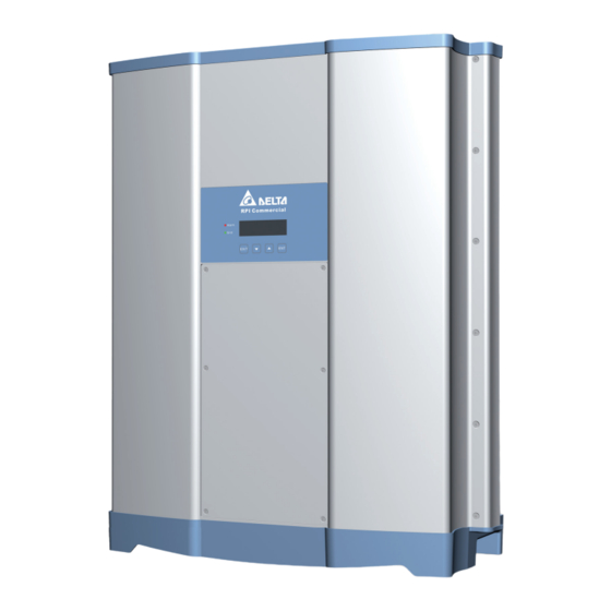
Page 4: Components Of The Inverter
Components of the inverter Display, buttons, LEDs String fuses (M50A_120 and M50A_122) and AC- and DC overvoltage protection Type II (M50A_120 only) Electrical connectors Air inlets Fans Type label DC Inputs AC/DC Disconnection switch AC Connector Communication port 1 – –... -
Page 5: Informationen On The Type Label
Information on the type label Type label RPI M50A_120 Type label RPI M50A_122 Risk of death by electrocution Potentially fatal voltage is present when the solar inverter is in operation that remains for 10 seconds after being disconnected from power Never open the solar inverter The solar inverter contains no components that must be maintained or repaired by 10 seconds the operator or installer Opening the cover will void the warranty... -
Page 6: Planing The Installation
Planning the installation ► The solar inverter is very heavy, Where to mount the inverter see section “Technical data” The solar inverter must be lifted and 74 kg carried by at least three people ► Always use the mounting plate supplied with the solar inverter ►... -
Page 7: Mounting The Inverter
Mounting the inverter ► Fasten the mounting plate to the wall (max 12 screws) ► Hang the solar inverter into the mounting plate ► Check that the rail of the solar inverter hangs correctly in the mounting plate ► On the left side, ground the solar inverter housing Toothed ring Grounding cable... -
Page 8: Connecting To The Grid (Ac)
Connecting to the grid (AC) DANGER Risk of death or serious injury from electrocution ► Set the AC/DC disconnection switch to position OFF before connecting or disconnecting the AC plug ► For a description how to set the AC connection type on the display, see “Setting AC connection type”, p 15 DISCONN AC/DC... - Page 9 VDE 0100-712 your country! Grounding the inverter The possibilities of faults were examined by Delta without tak- ing the integrated RCMU (residual-current monitoring unit) into The inverter must be grounded via the AC connector’s PE con- account When examining these faults in terms of the current...
-
Page 10: Connecting To The Solar Modules (Dc)
Connecting to the solar modules (DC) DANGER Risk of death or serious injury from electrocution Potentially fatal voltage may be applied to the DC connections of the solar in- verter When light is falling on solar modules, they immediately start producing energy They do so, even when the sun is not shining ►... -
Page 11: Connecting To A Datalogger Via Rs485 (Optional)
VCC, unless you want to use it, e g for an external relais If you want to use SOLIVIA Monitor the Internet based monitoring from Delta, you will also need a SOLIVIA M1 G2 Gateway Default baud rate is 19200 which can be changed on the inverter (see “Setting the baud rate for RS485”, p... -
Page 12: Connecting Digital Inputs, Epo And Dry Contacts (Optional)
Connecting digital inputs, EPO and dry contacts (optional) VCC switch and RS485 termination resistor – Dry contacts EPO and digital inputs DC 2 COMM. Communication port Interface for VCC and RS485 Digital inputs and EPO (Emergency Power Off) Dry contacts The digital inputs can be used to connect an external ripple con- When the fans fail, Dry contact 1 is closed trol receiver for controlling the active power... -
Page 13: Commissioning - Basic Settings
Commissioning - basic settings To execute commissioning, the inverter needs to be powered either by AC (the grid) or DC (the solar modules) After powering up the inverter for the fi rst time, the Select language dialog is shown DISCONN AC/DC S e l e c t l a n g u a g e Use the buttons to select language English... -
Page 14: Commissioning - Further Settings
Commissioning - further settings The settings described in this section may not be relevant for your installation ► Check each setting whether it is needed for you Setting date and time When the default information is displayed, press any button to open the main menu 1 0 . -
Page 15: Setting The Inverter Id
Setting the inverter ID If your PV plant contains multiple inverters, for each of the inverters a different inverter ID has to be set The inverter ID is needed to identify each inverter For a description of the RS485 connection, see “Con- necting to a datalogger via RS485 (optional)”, p 11 When the default information is displayed, press any button to open the main menu... -
Page 16: Setting A Power Limitation
This setting is protected by a special password To get the password, please call the Delta Support hotline in your country. You can fi nd the telephone number on the last page of this quick installation guide. -
Page 17: Setting Dry Contacts
Setting dry contacts For a description of the dry contacts, see “Connecting digital inputs, EPO and dry contacts (optional)”, p 12 When the default information is displayed, press any button to open the main menu 1 0 . S e p 2 0 1 4 1 5 : 3 2 Otherwise, repeatedly press the button until the main menu is displayed S t a t u s :... -
Page 18: Technical Data
Technical data Input (DC) RPI M50A_120 RPI M50A_122 Maximum recommended PV power 70 kW Maximum input power 58 kW Nominal power 52 kW Input voltage range 1000 V Maximum input voltage 1000 V Nominal voltage 600 V Startup voltage 250 V Startup power 40 W MPP input voltage range with full power... - Page 19 DC Connector type Multi-Contact MC4 Communication interfaces 2 x RS485, 2 x Dry contacts, 1 x EPO, 6 x Digital inputs General Specification RPI M50A_120 RPI M50A_122 Delta model name RPI M50A_120 RPI M50A_122 Delta part number RPI503FA0E0000 RPI503FA0E0200 Maximum efficiency...
-
Page 20: Service Europe
0800 051 4281 (call free) Other European countries support europe@solar-inverter com +49 7641 455 549 5013222900 01 © Copyright – Delta Energy Systems (Germany) GmbH – All rights reserved 02 12 2014 - All information and specifications can be modified without prior notice.
Need help?
Do you have a question about the RPI M50A 120 and is the answer not in the manual?
Questions and answers