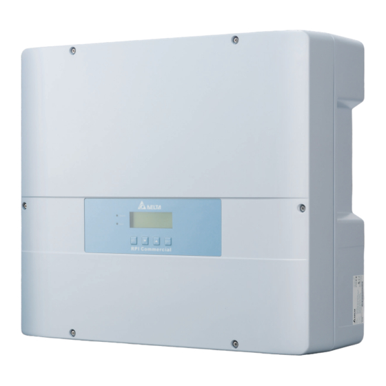
Delta RPI M6A Operation And Installation Manual
Grid-tie transformerless solar inverter
Hide thumbs
Also See for RPI M6A:
- Installation and operation manual (116 pages) ,
- Operation and installation manual (44 pages) ,
- Quick installation manual (29 pages)

Related Manuals for Delta RPI M6A


Summary of Contents for Delta RPI M6A
- Page 1 The power behind competitiveness Grid-tie Transformerless Solar Inverter RPI M6A/M8A/M10A Operation and Installation Manual www.deltaww.com...
-
Page 3: Table Of Contents
Contents 1. General Information 1.1. About this Manual 1.2. Product Description 1.3. Additional Information 2. Product Overview 2.1. Checking Unit and Accessories 2.2. Product Label 2.3. Exterior Objects 3. Installation 3.1. Unpack the Inverter 3.2. Mount the Inverter 4. Wiring 4.1 Preparation before Wiring 4.2. - Page 4 Safety Instructions This manual uses the following instructions for conveying important safety related information. CAUTION ! Machine and equipment damage may occur if this hazardous situation is not avoided. WARNING ! Death and serious injury may occur if this hazardous situation is not avoided.
-
Page 5: General Information
This manual is to provide the explanation and procedures for installing, operating, maintaining, and troubleshooting the below solar inverters: RPI M6A/ RPI M8A/ RPI M10A 1.2. Product Description This device is a 3-phase grid-tied solar inverter which does not support off- grid functionality. -
Page 6: Product Overview
Figure 2-1 Packing list RPI M6A/ RPI M8A/ RPI M10A Object Qty Description PV Inverter RPI M6A/ RPI M8A/ RPI M10A solar inverter. a. User Manual b. Quick Installation Guide The Instruction to provide the information of (EU/AU/ EN/ DE/ FR/ NL) safety,Installation, specification, etc. -
Page 7: Product Label
Product Overview 2.2. Product Label Users can identify the model number and the specifications by the information on the product label. The location for the label please see Figure 2-2. RPI M6A/ M8A/ M10A Figure 2-2 Product label... -
Page 8: Exterior Objects
Product Overview 2.3. Exterior Objects The Inverter’s exterior objects are shown in Figure 2-3. The detailed input/ output interfaces illustration is shown in Figure 2-4. RPI M6A/ M8A/ M10A LCD/LED Display and Buttons Manual Switch DC Connectors Communication Connection 1... -
Page 9: Installation
Installation 3.Installation CAUTION ! The unit should not be installed in direct sunlight. WARNING ! • Do not install the unit near or on flammable surfaces. • Please mount the unit tightly on a solid/smooth surface. 3.1. Unpack the Inverter Figure 3-1 Unpacking the inverter... -
Page 10: Mount The Inverter
Installation 3.2. Mount the Inverter This unit is designed to be wall-mounted. Please ensure the installation is perpendicular to the floor and the AC plug at the bottom. Do not install the device on a slanting wall. To mount the inverter on the wall, please follow the procedure below: 1.Screw the mounting bracket on the wall with 8 M6 Phillips head screws. - Page 11 Installation Figure 3-3 Mounting bracket dimension Figure 3-4 Screw the mounting bracket...
- Page 12 Installation M4 Hexagon Socket Screw M4 Hexagon Socket Screw Figure 3-5 Attach inverter to the bracket and fasten with screws CAUTION ! • The bracket supplied with the unit is specially designed and should be the only mounting device used for the unit. •...
- Page 13 Installation > 20 CM > 20 CM Figure 3-6 Proper installation gap...
-
Page 14: Wiring
4.1. Preparation before Wiring • When grounding the solar array, an isolation transformer is required due to the RPI M6A/ M8A/ M10A not having galvanic isolation between the DC-input and AC-output. Wiring illustrations please refer to Figure 4-1. • Inverters provide DC inputs in parallel (2 MPP tracker/ 3 parallel inputs). -
Page 15: Ac Grid Connection: 3-Phase+Pe Or 3-Phase+N+Pe
It is recommended to install an upstream circuit breaker between AC side and inverter side for over current protection. Model Upstream circuit breaker RPI M6A/ M8A/ M10A Table 4-1 Recommended upstream protection To solar inverter AC plug G N L1 The AC cable must be jacked and meet the specifications in table 4-2. - Page 16 Wiring CAUTION!Machine and equipment damage may occur. • Make sure to choose proper size for AC cable. Please choose the terminals as shown in figure 4-2 for wires crimping. • Failed to follow these instructions may cause AC plug damage. Figure 4-2 Terminal for wire crimping Follow the steps below to strip the wires before assembling the AC plug as shown in Figure 4-3:...
- Page 17 Wiring RPI M6A/ M8A/ M10A use Amphenol AC connector with part number C016 20E004 800 2. Assemble the AC plug and wires as the procedures shown in Figure 4-4. The sequence of L1~ L3 can be random. However, N and PE must be connected correctly.
-
Page 18: Dc Connection (From Pv Array)
Rated current > short-circuit current of PV Array. • The input power to the inverter should not higher than the rated power shown in table 4-3. Type of limit RPI M6A RPI M8A RPI M10A 7 kW 4.25 kW 5.65 kW... -
Page 19: Multiple Inverter Combinations
Wiring 4.4. Multiple Inverter Combinations 4.4.1. Three-Phase Parallel Combination System RPI M6A/8A/10A can be used in three-phase parallel combination system. In this application, inverter may be parallel connected to a same AC grid. Please refer to Figure 4-6. L1 (Grid) -
Page 20: Communication Module Connections
Wiring 4.4.2. Communication Module Connections The Communication 1 Module illustration please see Figure 4-7, the module supports a RS-485 terminal for communication with a computer. The Communication 2 Module illustration please see Figure 4-7, the module Supports Digital Input, Demand Response Modes (DRMs), EPO, Dry Contact and DC Output : 12V / 0.5A RS-485 Communication 1... -
Page 21: Rs-485 Connection
ON terminal resister at the first and last devices of the RS-485 chain as shown. Other terminal resisters should be switched OFF. Function VCC (+12V) DATA+ DATA- DATA+ DATA- RPI M6A/ M8A/ M10A Table 4-5 Definition of RS 485 pin Terminal Resister 120Ω(1/2W) DATA+ to DATA- Terminal Resister 120Ω(1/2W) Data Format:... - Page 22 Wiring EPO, digital input function and DRMs can be parallel connection in multi-inverter operation, refer to Figure 4-9 for the connection. EPO Button K1 (0% Power) INV_1 K2 (30% Power) K3 (60% Power) K4 (100% Power) K1 (0% Power) INV_2 K2 (30% Power) K3 (60% Power) K4 (100% Power)
-
Page 23: Digital Input & Epo Function & Drms
Wiring 4.4.4. Digital Input & EPO Function & DRMs Communication 2 Module has 1 set of emergency power off function (EPO). Users can customize EPO function in Install Settings page. Please refer to section 5.3.6.6 EPO. also provides 4 sets of digital input function (K1~K4). Please refer to Table 4-7 In Australia (AU 2015) and New Zealand (NZ 2015), the DRMs are also use digital input function to assert. -
Page 24: Dry Contact Connection
Figure 4-11 Dry contact port 4.4.6. DC Output Connection RPI M6A/ M8A/ M10A provide 1 set of DC Output and it can be used by external device (EX: Alarm light or Buzzer). The output spec is 12V / 0.5A max and its connector in packing, please refer to Table 2-1 Packing list. -
Page 25: Turn On/Off Pv Inverter
Turn on/off PV inverter 5.Turn on / off PV inverter WARNING ! BURN HAZARD The enclosure temperature may exceed 70°C while inverter is operation. A dangerous burn hazard is present in this situation. 5.1. First startup At first startup, users have to feed in AC power and switch on the Manual Switch. -
Page 26: Home Page
Turn on/off PV inverter Condition Green LED Red LED Standby or Countdown FLASH * Power ON Error or Fault Night time (No DC) Bootloader mode FLASH * *1 ON 1s / OFF 1s *2 ON 1s / OFF 1s, Green and Red are interleaving Table 5-1 LED indicator Select Language, Setting ID:... -
Page 27: Lcd Flow Chart
Turn on/off PV inverter 5.3. LCD Flow Chart Press any key at home page can users enter main menu page (shown as Figure 5-4). Press Esc key at main menu can go back to homepage. When users adjust settings, the cursor on display will change from “►” to “... -
Page 28: Energy Log
Turn on/off PV inverter 5.3.2. Energy Log User can view the inverter’s life energy and life runtime via Energy Log page. Life Energy ►Life Energy E-Total: 29200 Day Energy Runtime: 7302 Month Energy EXIT Energy Day Life Energy 2013.06.21 7935 ►Day Energy 2013.06.20 1234... -
Page 29: Inverter Information
Turn on/off PV inverter 5.3.4. Inverter Information This page can helps user to recognize the inverter. First section displays serial number, installation date, ID, and firmware version. Another 3 sections displays the settings of inverter functions. For more infromation about these settings, please refer to 5.3.6 Install Settings, 5.3.7 Active/Reactive power, and 5.3.8 FRT (Fault ride through). -
Page 30: General Settings
Turn on/off PV inverter 5.3.5. General Settings Users can set Language, Date and Time, and RS-485 communication baud rate in this page. Language ► Date and Time Baud Rate Figure 5-9 General Settings page 5.3.6. Install Settings CAUTION! The settings in Install Settings page can only be adjusted by qualified installers or engineers. -
Page 31: Inverter Id
5.3.6.2. Insulation Before connecting to grid, inverter will measure the impedance between the PV array and PE first. RPI M6A/ M8A/ M10A models provide 6 types of impedance measurement methods (ON, DC1 only, DC2 only, Plus Grounded, Minus Grounded, and OFF) and 3 impedance limits. Installer must select the appropriate method based on PV array’s wiring. -
Page 32: Grid Settings
Turn on/off PV inverter 5.3.6.4. Grid Settings Grid settings page includes the voltage and frequency protection points. These protection points are linked to electricity regulations. If there is no any special requirement, please do not change any grid settings. Inverter ID: 002 Voltage Protection High Off 276.0V... -
Page 33: Dry Contact
Turn on/off PV inverter 5.3.6.5. Dry Contact Users can choose the trigger condition of dry contact. There are 8 options in the setting page: Disable, On Grid, Fan Fail, Insulation, Alarm, Error, Fault, and Warning. Please refer to Table 5-2 for more details about these options. -
Page 34: Epo
Dry Cont. Insulation RCMU ► Normal Open Figure 5-16 EPO page 5.3.6.7. AC connection RPI M6A/ M8A/ M10A models can support 3P3W and 3P4W system. Please select the correct AC wiring type. AC Connection 3P4W ► Anti-islanding Max. Power 10500W... -
Page 35: Active/Reactive Power
Turn on/off PV inverter 5.3.7. Active/Reactive power A password is required to enter Active/Reactive Power page. This page includes two kinds of function: active power control and reactive power control. In active power control function, there are 3 control modes: Power Limit, Power vs. -
Page 36: Power Vs. Frequency
Turn on/off PV inverter 5.3.7.2. Power vs. Frequency Inverter will reduce output power when grid frequency rises up if this mode enabled. Users can tune the parameters in Power vs. Frequency page to change the inverter’s behavior. Power Limit Mode ►... -
Page 37: P(V)
Turn on/off PV inverter 5.3.7.3. P(V) When grid voltage rises up to a lock-in voltage(V lock-in) and inverter’s present output power is greater than lock-in power(P lock-in), inverter will reduce the output power and keep it at a certain value(P lock-out) until grid voltage drop back to lock-out voltage(V lock-out) and passing a certen time(T revcovery). -
Page 38: Cosphi (P)
Turn on/off PV inverter 5.3.7.5. Cosphi (P) Cosphi (P) is a function that inverter will feed in reactive power when its output active power reach the setting values. For country Italy MV and Italy LV, users can set lock-in voltage and lock-out voltage to assign the operation interval. -
Page 39: Constant Q
Turn on/off PV inverter 5.3.7.6. Constant Q Like Constant cosphi function, users can assign a percentage of reactive power in Constant Q page. Constant cosphi Mode ► Cosphi (P) Fix Q Ind 90% ► Constant Q Q(V) EXIT Figure 5-27 Cosphi (P) parameters 5.3.7.7. -
Page 40: Frt (Fault Ride Through)
Turn on/off PV inverter Others Italy MV & Italy LV i limit i limit s limit s limit Curve A Curve B Figure 5-29 Q(V) parameters 5.3.8. FRT (Fault ride through) Some area requests that inverter should keep connected to grid when grid voltage drops suddenly in few seconds. -
Page 41: Maintenance
Maintenance 6.Maintenance In order to ensure normal operation of the inverter, please check the unit regularly. Check that all terminals, screws and cables are connected and appeared as they did upon installation. If there are any impaired or loose parts, please contact your solar installer. -
Page 42: Error Message And Trouble Shooting
Error message and Trouble Shooting 7.Error message and Trouble Shooting ERROR Message Possible cause Action 1. Actual utility frequency is over 1. Check the utility frequency on the the OFR setting inverter terminal AC Freq 2. Check country setting High 2. - Page 43 Error message and Trouble Shooting ERROR Message Possible cause Action 1. Actual Solar1 voltage is over 1. Modify the solar array setting, and Solar1 1000Vdc make the Voc less than 1000Vdc High 2. Detection circuit malfunction 2. Check the detection circuit inside the (E30) inverter 1.
- Page 44 Error message and Trouble Shooting FAULT Message Possible cause Action 1. Utility waveform is 1. Check the utility waveform. abnormal Grid connection of inverter need to be Injection far away from non-linear load if necessary 2. Detection circuit (F01, F02, malfunction 2.
- Page 45 Error message and Trouble Shooting FAULT Message Possible cause Action 1. Insufficient input power 1. Check the input voltage, must >150Vdc 2. Auxiliary power circuitry 2. Check the auxiliary circuitry inside the HW DSP inverter ADC2 malfunction 3. Check the detection circuit inside the (F16) 3.
- Page 46 Error message and Trouble Shooting FAULT Message Possible cause Action 1. Power line is disconnected 1. Check the power lines inside the inverter inside the inverter 2. Check the current feedback circuit inside HW Con. Fail 2. Current feedback circuit is the inverter (F26) defective...
- Page 47 Error message and Trouble Shooting FAULT Message Possible cause Action 1. Test current loop is broken 1. Check the connection of CNP4 to CNM4 2. CTP4 is defective 2. Replace CTP4 with new one HW CT B Fail (F43) 3. Detection circuit malfunction 3.
-
Page 48: De-Commissioning
De-Commissioning 8.De-Commissioning If it is necessary to put the device out of operation for maintenance or storage, please follow the instructions below. WARNING! To avoid injuries, please follow the procedures: • Switch off AC circuit breaker to disconnect with electricity grid. •... -
Page 49: Technical Data
Technical Data 9.Technical Data RPI M6A RPI M8A RPI M10A GENERAL Enclosure Powder coated aluminum Operating temperature -25~60℃ , full power up to 40℃ Operating Altitude 2000m Relative humidity 0 – 100% non-condensing. Environmental category Outdoor, wet locations Protection degree... - Page 50 Technical Data RPI M6A RPI M8A RPI M10A MPPT range at Nominal Power Balanced inputs 315~800Vdc 415~800Vdc 415~800Vdc Unbalanced inputs 425~800Vdc 565~800Vdc 415~800Vdc DC INPUT (Solar side) MPPT1 (1pair MC4) MPPT1 (2pair MC4) Number of inputs MPPT2 (1pair MC4) MPPT2 (1pair MC4)
- Page 51 IEC 61000-4-8 Electrical safety IEC 62109-1/ -2 MISCELLANEOUS Mounting bracket Enclosure Aluminum with powder coating (1) 4.99kW max. for Australia (AU / NZ PL 4.99kW). (2) 6.3kW max. for Australia (AU / NZ). Table 9-1 Specifications for RPI M6A/ M8A/ M10A...
- Page 52 5013217108 Version 09170223...
Need help?
Do you have a question about the RPI M6A and is the answer not in the manual?
Questions and answers