Delta RPI M6A Operation And Installation Manual
Grid-tie transfomerless solar inverter
Hide thumbs
Also See for RPI M6A:
- Installation and operation manual (116 pages) ,
- Operation and installation manual (52 pages) ,
- Quick installation manual (29 pages)

Related Manuals for Delta RPI M6A


Summary of Contents for Delta RPI M6A
- Page 1 The power behind competitiveness Grid-tie Transfomerless Solar Inverter RPI M6A / M8A / M10A Operation and Installation Manual www.deltaww.com...
-
Page 3: Table Of Contents
Contents 1. General Information --------------------------------------------------------------5 1.1. About this Manual ------------------------------------------------------------ 5 1.2. Product Description ---------------------------------------------------------- 5 1.3. Additional Information ------------------------------------------------------- 5 2. Product Overview -----------------------------------------------------------------6 2.1. Checking Unit and Accessories ------------------------------------------- 6 2.2. Product Label ------------------------------------------------------------------ 7 2.3. Exterior Objects --------------------------------------------------------------- 7 3. - Page 4 Safety Instructions This manual uses the following instructions for conveying important safety related information. CAUTION ! Machine and equipment damage may occur if this hazardous situation is not avoided. WARNING ! Death and serious injury may occur if this hazardous situation is not avoided.
-
Page 5: General Information
This manual is to provide the explanation and procedures for installing, operating, maintaining, and troubleshooting the below solar inverters: RPI M6A/ RPI M8A/ RPI M10A 1.2. Product Description This device is a 3-phase grid-tied solar inverter which does not support off-grid functionality. -
Page 6: Product Overview
Figure 2-1 Packing listUnit RPI M6A/ RPI M8A/ RPI M10A Object Description PV Inverter RPI M6A/ RPI M8A/ RPI M10A solar inverter The Instruction to provide the information of safety, User Manual Installation, specification, etc. AC Plug Connector for AC connection Mounting Bracket To mount solar inverters on the wall. -
Page 7: Product Label
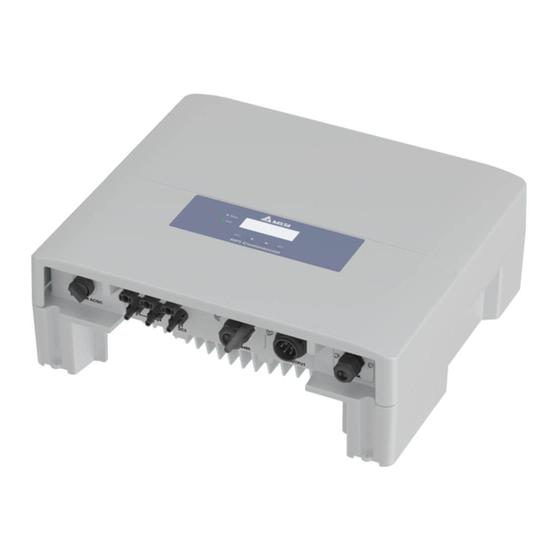
Users can identify the model number and the specifications by the information on the product label. The location for the label please sees Figure 2-2. RPI M6A/ M8A/ M10A Figure 2-2 Product label 2.3. Exterior Objects The Inverter's exterior objects are shown in Figure 2-3. The detailed input/output interfaces illustration is shown in Figure 2-4. - Page 8 Product Overview RPI M6A/ M8A AC Connector Grounding AC/DC Switch Mark 400Vac, 3Ph Communication 1 Communication 2 -RS-485 *2 -EPO *1 -Ethernet (optional) -Dry Contact *1 -Wi-Fi (optional) -Digital Input*6 RPI M10A Figure 2-4 Input/output panels...
-
Page 9: Installation
Installation 3.Installation CAUTION ! The unit should not be installed in a direct sunlight. WARNING ! • Do not install the unit near or on flammable surfaces. • Please mount the unit tightly on a solid/smooth surface. 3.1. Unpack the Inverter Figure 3-1 Unpacking the inverter... -
Page 10: Mounting Position
Installation 3.2. Mounting position This unit is designed to be wall-mounted. Please ensure the installation is perpendicular to the floor and the AC plug at the bottom. Do not install the device on a slanting wall. Fix the supplied wall-mount plate securely on the wall before attaching the inverter onto the mounting plate. -
Page 11: Mounting Dimension
Installation 3.3. Mounting braket Dimension Figure 3-3 Mounting bracket demension... - Page 12 Installation M4 Screw M4 Screw Figure 3-4 Attach inverter to the bracket and fasten with screws...
- Page 13 Installation CAUTION ! • The bracket supplied with the unit is specially designed and should be the only mounting device used for the unit. • It is recommended to install the inverter in a suitable location which offers non-obscured and safe access, in turn ensuring easy access for service and maintenance.
-
Page 14: Wiring
4.Wiring 4.1. Preparation before Wiring • When grounding the solar array, an isolation transformer is required due to the RPI M6A/ M8A/ M10A not having galvanic isolation between the DC-input and AC-output. Wiring illustrations please refer to Figure 4-1. • Inverters provide DC inputs in parallel (2 MPP tracker/ 3 parallel inputs). -
Page 15: Ac Grid Connection: 3-Phase+Pe Or 3-Phase+N
It is recommended to install an upstream circuit breaker between AC side and inverter side for over current protection. Model Upstream circuit breaker RPI M6A/ M8A/ M10A Table 4-1 Recommended upstream protection To solar inverter AC plug G N L1 The AC cable must be jacked and meet the specifications in table 4-2. - Page 16 Wiring CAUTION ! Machine and equipment damage may occur. • Make sure to choose proper size for AC cable. Please choose the terminals as shown in figure 4-2 for wires crimping. • Failed to follow these instructions may cause AC plug damage. Figure 4-2 Terminal for wire crimping Follow the steps below to strip the wires before assembling the AC plug as shown in Figure 4-3:...
- Page 17 Rotate to tighten the plug Rotate to tighten the inserter fix cable Figure 4-4 AC plug illustration for RPI M6A/ M8A/ M10A. After wiring, installer should choose the AC connection type on the control panel. About setting, please refer to 5.3.6 Install Settings.
-
Page 18: Dc Connection (From Pv Array)
Rated current > short-circuit current of PV Array. • The input power to the inverter should not higher than the rated power shown in table 4-3. Type of limit RPI M6A RPI M8A RPI M10A Total input power 6.5 kW 8.6 kW... -
Page 19: Communication Module Connections
Wiring 4.4. Communication Module Connections The Communication Module illustration please see figure 4-6 , the module supports a RS-485 terminal for communication with a computer. RS-485 Terminal Resistor Communication 1 Dry Contact Digital Input*6 EPO*1 Communication 2 Figure 4-6 Communication module... -
Page 20: Rs-485 Connection
RS485 chain as shown. The other terminal resisters should be switched OFF. Function VCC (+12V) DATA+ DATA- DATA+ DATA- RPI M6A/ M8A/ M10A Table 4-5 Definition of RS 485 pin Terminal Resister 120Ω(1/2W) DATA+ to DATA- Terminal Resister 120Ω(1/2W) Data Format:... -
Page 21: Digital Input & Epo Functions
1 set of emergency power off function (EPO). When the outer external switch is short-circuited, the inverter will reduce power or shutdown immediately. Digital Input*6 EPO*1 RPI M6A/ M8A/ M10A Figure 4-8 EPO functions Inverter ’ s action Define Short VCC &... -
Page 22: Dry Contact Connection
Wiring 4.4.3. Dry Contact Connection RPI M6A/ M8A/ M10A provide 1 set of Dry Contact function. When inverter is on grid, these two pins will be short-circuited. Dry Contact RPI M6A/ M8A/ M10A Figure 4-9 Dry contact port... -
Page 23: Turn On/Off Pv Inverter
Turn on/off PV inverter 5.Turn on/off PV inverter WARNING ! BURN HAZARD The enclosure temperature may exceed 70 ° C while inverter is operation. A dangerous burn hazard is present in this situation. 5.1. First startup Turn AC power switch ON in AC distribution box, AC power can be fed into inverter. -
Page 24: Home Page
Turn on/off PV inverter First Startup Figure 5-2 Country and language settings for first startup 5.2. Home Page When inverter is operating normally, the LCD will display homepage as shown in Figure 5-3, user can get the information of output power, inverter status, E-today, date and time. -
Page 25: Power Meter
Turn on/off PV inverter 5.3.1. Power Meter This page displays voltage, current and power from both AC and DC side. Figure 5-5 Power meter page 5.3.2. Energy Log Press ENT to view the historical data on the power generated. Energy Log, Life Energy: 29200 Runtime:... -
Page 26: Event Log
Turn on/off PV inverter 5.3.3. Event Log This page displays all error or fault events and it can show 30 records at a time. The latest event will be showed on the top. Figure 5-7 Event log flow chart 5.3.4. Inverter Information This page has the following information: serial number, firmware version, inverter ID, country, insulation setting. -
Page 27: General Settings
Turn on/off PV inverter 5.3.5. General Settings Language, date, time, and Wi-Fi ON/OFF can be set in the General Settings. ► Language Date and Time Wi-Fi: OFF Figure 5-9 General Settings page 5.3.6. Install Settings CAUTION ! The following settings can only be adjusted by installers. Changing these settings may result in damage to the inverter and other equipments. -
Page 28: Active/Reactive Power
Turn on/off PV inverter 5.3.7. Active/Reactive power A password is required to enter Active/Reactive Power page. This page includes two kinds of function: active power control and reactive power control. In active power control function, there are 3 control modes: Power Limit, Power vs. Frequency, and P(V). In reactive power control function, there are 4 control modes: Constant cosphi, cosphi(P), Constant Q, and q(V). - Page 29 Turn on/off PV inverter 5.3.7.2 Power vs. Frequency Inverter will reduce output power when grid frequency rises up if this mode enabled. Users can tune the parameters in Power vs. Frequency page to change the inverter ’ s behavior. ► Power Limit Mode ►...
- Page 30 Turn on/off PV inverter 5.3.7.4 Constant cosphi Inverter can feed in a fixed reactive power to grid. Users can set the power factor(cosphi) in Constant cosphi page. ► Constant cosphi ► Mode Cosphi (P) cosphi Ind 1.00 Constant Q Q(V) EXIT Figure 5-16 Constant cosphi page 5.3.7.5 Cosphi (P)
- Page 31 Turn on/off PV inverter 5.3.7.6 Constant Q Like Constant cosphi function, users can assign a percentage of reactive power in Constant Q page. ► Constant cosphi Mode Cosphi (P) Fix Q Ind 90% ► Constant Q Q(V) EXIT Figure 5-18 Cosphi (P) parameters 5.3.7.7 Q(V) Q(V) is a control mode that inverter will provide reactive power accroding to grid voltage.
-
Page 32: Frt (Fault Ride Through)
Turn on/off PV inverter Others Italy MV & Italy LV i limit i limit s limit s limit Curve A Curve B Figure 5-20 Q(V) parameters 5.3.8. FRT (Fault ride through) Some area requests that inverter should keep connected to grid when grid voltage drops suddenly in few seconds. -
Page 33: Maintenance
Maintenance 6.Maintenance In order to ensure normal operation of the inverter, please check the unit regularly. Check that all terminals, screws and cables are connected and appeared as they did upon installation. If there are any impaired or loose parts, please contact your solar installer. Ensure that there are no foreign objects in the path of the heat outlet and keep the unit and its surroundings clean and tidy. -
Page 34: Error Message And Trouble Shooting
Error message and Trouble Shooting 7.Error message and Trouble Shooting ERROR Message Possible cause Action 1. Actual utility frequency is 1. Check the utility frequency on the over the OFR setting inverter terminal AC Freq 2. Incorrect country setting 2. Check country setting High 3. - Page 35 Error message and Trouble Shooting ERROR Message Possible cause Action 1. Actual Solar1 voltage is 1. Modify the solar array setting, and over 1000Vdc make the Voc less than 1000Vdc Solar1 High 2. Detection circuit malfunction 2. Check the detection circuit inside the inverter 1.
- Page 36 Error message and Trouble Shooting FAULT Message Possible cause Action 1. Utility waveform is abnormal 1. Check the utility waveform. Grid connection of inverter need to be 2. Detection circuit malfunction far away from non-linear load if HW DC necessary Injection 2.
- Page 37 Error message and Trouble Shooting FAULT Message Possible cause Action 1. Insufficient input power 1. Check the input voltage, must > 150Vdc 2. Auxiliary power circuitry HW DSP malfunction 2. Check the auxiliary circuitry inside ADC2 3. Detection circuit the inverter malfunction 3.
- Page 38 Error message and Trouble Shooting FAULT Message Possible cause Action 1. PV array insulation fault 1. Check the insulation of Solar inputs 2. Large PV array capacitance 2. Check the capacitance (+ <-> GND between Plus to Ground or & - <-> GND), must < 2.5uF. Install Ground Minus to Ground a external transformer if necessary...
- Page 39 Error message and Trouble Shooting FAULT Message Possible cause Action 1. Surge occurs during 1. N/A operation 2. Check the driver circuit in inverter 2. Driver for inverter stage is stage AC Current defective 3. Check all switching devices in High 3.
-
Page 40: Commissioning
De-Commissioning 8.De-Commissioning If it is necessary to put the device out of operation for maintenance or storage, please follow the instructions below. WARNING ! To avoid injuries, please follow the procedures: • Switch off AC circuit breaker to disconnect with electricity grid. •... -
Page 41: Technical Data
Technical Data 9.Technical Data RPI M6A RPI M8A RPI M10A GENERAL Enclosure Powder coated aluminum -25~60 ℃ , full power up to 40 ℃ Operating temperature Operating Altitude 2000m Relative humidity 0 – 100% non-condensing. Environmental category Outdoor, wet locations... - Page 42 Technical Data RPI M6A RPI M8A RPI M10A AC OUTPUT (GRID SIDE) Nominal power 6kVA 8kVA 10kVA Maximum power 6.3kVA 8.4kVA 10.5kVA Voltage 3Ph, 230/400Vac (3phase / N / PE) Nominal current 8.7A 11.6A 14.5A Maximum current 9.7A Inrush current...
- Page 43 EN 61000-3-11 Immunity EN 61000-6-2 IEC 61000-4-2 IEC 61000-4-3 IEC 61000-4-4 Immunity Surge IEC 61000-4-5 IEC 61000-4-6 PFMF IEC 61000-4-8 Electrical safety IEC 62109-1/ -2 MISCELLANEOUS Mounting bracket Enclosure Aluminum with powder coating Table 9-1 Specifications for RPI M6A/ M8A/ M10A...
Need help?
Do you have a question about the RPI M6A and is the answer not in the manual?
Questions and answers