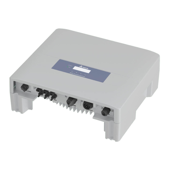
Delta RPI M6A Installation And Operation Manual
Solar inverter
Hide thumbs
Also See for RPI M6A:
- Operation and installation manual (52 pages) ,
- Quick installation manual (29 pages) ,
- Installation manual (28 pages)

Related Manuals for Delta RPI M6A


Summary of Contents for Delta RPI M6A
- Page 1 Installation and Operation Manual RPI M6A RPI M8A RPI M10A Europe Australia New Zealand...
- Page 2 All information and specifications can be modified without prior inverter.com. notice. Delta Energy Systems (Germany) GmbH Tscheulinstrasse 21 79331 Teningen Germany Installation and Operation Manual for RPI M6A M8A M10A inverters V1.0 2016-02-03...
-
Page 3: Table Of Contents
Dry contacts ..........44 Installation and Operation Manual for RPI M6A M8A M10A inverters V1.0 2016-02-03... - Page 4 13. Technical data ........... . 113 Installation and Operation Manual for RPI M6A M8A M10A inverters V1.0 2016-02-03...
-
Page 5: About This Manual
This symbol is a warning of a risk of electric shock due to high voltage. This symbol is a warning of a hot surface. This symbol is a warning of general haz- ards. Installation and Operation Manual for RPI M6A M8A M10A inverters V1.0 2016-02-03... -
Page 6: Conventions Used In This Manual
Information shown on the inverter display includes menus, set- tings and messages. This information is shown in this manual as follows: Menu names: User settings menu Parameter names: Cos phi parameter Installation and Operation Manual for RPI M6A M8A M10A inverters V1.0 2016-02-03... -
Page 7: General Safety Instructions
Do not disconnect any cables when the solar inverter is pow- ered due to risk of a fault arc. ● To prevent lightning strikes, follow the relevant regulations applicable in your country. Installation and Operation Manual for RPI M6A M8A M10A inverters V1.0 2016-02-03... -
Page 8: Intended Use
Any of the following uses of the inverter is considered improper: ● Isolated operation. The inverter has anti-islanding and other monitoring features. ● Use in mobile PV systems. Installation and Operation Manual for RPI M6A M8A M10A inverters V1.0 2016-02-03... -
Page 9: Ec Declaration Of Conformity
This declaration certifies the conformity to the specified directives but contains no assurance of properties. The safety documentation accompanying the product shall be considered in detail. Deschap RPI M6_10A EC_Decl EN 2014A.doc Installation and Operation Manual for RPI M6A M8A M10A inverters V1.0 2016-02-03... -
Page 10: Product Overview
Installation and Operation Manual RPI M6A RPI M8A RPI M10A DC plugs Europe Multi-Contact MC4 plug for DC– (32.0016P0001-UR for 4/6 mm M6A: 2 M8A: 2 M10A: 3 Installation and Operation Manual for RPI M6A M8A M10A inverters V1.0 2016-02-03... -
Page 11: Components And Connectors
See “4.4 Electrical connectors”, p. 13 Type label See “4.6 Information on the type label”, p. 17 Mounting and grounding holes See “4.5 Mounting and grounding holes”, p. 16 Installation and Operation Manual for RPI M6A M8A M10A inverters V1.0 2016-02-03... -
Page 12: Display, Buttons, Status Leds
Move downwards in menu. Set value (decrease). Move up Move upwards in menu. Set value (increase). Select menu item. Open configurable value for editing. Finish editing (adopt set Enter value). Installation and Operation Manual for RPI M6A M8A M10A inverters V1.0 2016-02-03... -
Page 13: Electrical Connectors
See “4.4.4 DC connectors (DC inputs)”, p. 15 RS485 port See “4.4.5 RS485 port”, p. 15 AC connector See “4.4.3 AC connector (AC output)”, p. 14 Communication port See “4.4.6 Communication port 2”, p. 15 Installation and Operation Manual for RPI M6A M8A M10A inverters V1.0 2016-02-03... -
Page 14: Ac/Dc Disconnection Switch
The AC plug is delivered with the inverter. The inverter is connected to the grid (AC) and the solar modules (DC) when the AC/DC Disconnection switch is in position ON. Installation and Operation Manual for RPI M6A M8A M10A inverters V1.0 2016-02-03... -
Page 15: Dc Connectors (Dc Inputs)
6 x Digital inputs (e.g. for connecting to a ripple control receiver) ● 1 x Dry contacts (e.g. for connecting to an external relais) ● 1 x External Power Off (EPO) Installation and Operation Manual for RPI M6A M8A M10A inverters V1.0 2016-02-03... -
Page 16: Mounting And Grounding Holes
Mounting and grounding holes The grounding connection is used for grounding the inverter housing. Grounding screw, spring washer, washer and toothed lock ring are delivered with the inverter. Installation and Operation Manual for RPI M6A M8A M10A inverters V1.0 2016-02-03... -
Page 17: Information On The Type Label
The housing of the inverter must be grounded if this is required by local regulations. Regulatory Compliance Mark (RCM mark): The inverter is compliant with the Australian Electri- cal Safety and EMC standards. Applies only to Australia and New Zealand. Installation and Operation Manual for RPI M6A M8A M10A inverters V1.0 2016-02-03... - Page 18 10kVA nom Nominal reactive power Maximum reactive power; 6.3kVA max The RPI M6A will be limited to 4.99 kW if grid type AU/NZ 8.4kVA max 10.5kVA max (1) 4.99 kW max for AU/NZ PL 4.99k is selected (applies to Australia and New Zea- PL 4.99k...
-
Page 19: Planning The Installation
► Mount the inverter on a vibration-free wall to avoid disruptive vibrations. ► Possible noise emissions can be disruptive when the device is used in living areas or in buildings with animals. Therefore, choose your installation location carefully. Installation and Operation Manual for RPI M6A M8A M10A inverters V1.0 2016-02-03... -
Page 20: Outdoor Installations
In this case you can try to cover the air inlets but be careful not to hinder the air flow. Alterna- tively, you can regularly clean air inlets and fans. Installation and Operation Manual for RPI M6A M8A M10A inverters V1.0 2016-02-03... -
Page 21: Ambient Conditions And Air Circulation
► Consider the operating temperature range (see ”13. Tech- nical data”, p. 113). When the operating temperature range is exceeded, the inverter reduces the amount of power generated. Installation and Operation Manual for RPI M6A M8A M10A inverters V1.0 2016-02-03... -
Page 22: Efficiency Curves
5 Planning the installation Efficiency curves 800 V DC 595 V DC Efficiency 315 V DC 100% Power [kW] Fig. 5.6: M6A efficiency curve Installation and Operation Manual for RPI M6A M8A M10A inverters V1.0 2016-02-03... - Page 23 5 Planning the installation 800 V DC 595 V DC Efficiency 415 V DC 100% Power [kW] Fig. 5.7: M8A efficiency curve Installation and Operation Manual for RPI M6A M8A M10A inverters V1.0 2016-02-03...
- Page 24 5 Planning the installation 800 V DC 595 V DC Efficiency 415 V DC 100% Power [kW] Fig. 5.8: M10A efficiency curve Installation and Operation Manual for RPI M6A M8A M10A inverters V1.0 2016-02-03...
-
Page 25: Dimensions
5 Planning the installation Dimensions Fig. 5.9: Dimensions of mounting plate Fig. 5.10: Dimensions of inverter (in mm) Installation and Operation Manual for RPI M6A M8A M10A inverters V1.0 2016-02-03... -
Page 26: Ac Connection
PV array and environmental conditions (e.g. humidity). The tripping current of the residual current device must not be less than the speci- fied minimum tripping current. Installation and Operation Manual for RPI M6A M8A M10A inverters V1.0 2016-02-03... -
Page 27: Dc Connection
Input Current DC 2 Fig. 5.13: I-U curve for symmetrical and asymmetrical power input (schematic diagrams) For currents and voltages see “13. Technical data”, p. 113. Installation and Operation Manual for RPI M6A M8A M10A inverters V1.0 2016-02-03... -
Page 28: Use With Solar Modules That Do Not Need To Be Grounded
PV array AC wiring 1 - L 2 - N DC wiring - PE Separate or parallel DC inputs – Fig. 5.14: System design with floating DC inputs Installation and Operation Manual for RPI M6A M8A M10A inverters V1.0 2016-02-03... -
Page 29: Use With Solar Modules That Have To Be Grounded
2 - L2 2 - L2 Negative grounding 3 - L3 3 - L3 – 4 - N - PE - PE Fig. 5.15: System design with floating DC inputs Installation and Operation Manual for RPI M6A M8A M10A inverters V1.0 2016-02-03... -
Page 30: Connecting Dc Strings To The Dc Terminals
– – – – DISCONN. AC/DC DC 1 AC OUTPUT DC INPUT Fig. 5.16: Connecting a single string to each DC terminal Installation and Operation Manual for RPI M6A M8A M10A inverters V1.0 2016-02-03... -
Page 31: Connecting To A Datalogger Via Rs485
Cable diameter: 5 mm ● Wire cross-section: 1 mm ● The RS485 cables should be kept separate from the AC cable and the DC cables to avoid interferences. Installation and Operation Manual for RPI M6A M8A M10A inverters V1.0 2016-02-03... -
Page 32: Dry Contacts
1) not recommend as it is more complicated than variant a) Check the type of communication card installed in your inverter before you plan how to connect dry contacts and digital inputs. Installation and Operation Manual for RPI M6A M8A M10A inverters V1.0 2016-02-03... - Page 33 RS485 terminal block Dry contacts plug Strobe light Buzzer Fig. 5.23: Providing a 12 V supply power for an external alarm device from the RS485 card, variant 2 Installation and Operation Manual for RPI M6A M8A M10A inverters V1.0 2016-02-03...
-
Page 34: Connecting A Pc To The Inverter
Beside the parts delivered with the inverter (see “4.1 Scope of delivery”, p. 10), you may need the following additional parts and tools. Installation and Operation Manual for RPI M6A M8A M10A inverters V1.0 2016-02-03... -
Page 35: What You Need
Wire end sleeves are needed to tightly mount the wires of the AC cables to the AC plug. Use a crimping tool to fasten the wire end sleeves to the wire. Wire end sleeves (bootlace pins) Installation and Operation Manual for RPI M6A M8A M10A inverters V1.0 2016-02-03... -
Page 36: For Connecting The Inverter To The Solar Modules
Safety caps must be used in France. Please check local regulations whether M6A/M8A: you have to use safety caps. up to 4 Safety caps M10A: up to 6 Installation and Operation Manual for RPI M6A M8A M10A inverters V1.0 2016-02-03... -
Page 37: For Grounding The Inverter Housing
Germany. The USB-RS485 adapter can be ordered at Delta. The cable RS485 cable can be standard cable. Delta Service Software To change the parameters for power limitation. Can be ordered at Delta. Installation and Operation Manual for RPI M6A M8A M10A inverters V1.0 2016-02-03... -
Page 38: Other Parts
Warning – Only persons authorised by the DNO may remove the main cut out fuse Safety labels Warning Two sources of voltage present Isolate both sources before carrying out any work - distribution network - photovoltaic panels Installation and Operation Manual for RPI M6A M8A M10A inverters V1.0 2016-02-03... -
Page 39: Installation
Read chapter “5. Planning the installation”, p. 19 and this chapter before you start instal- lation. Never open the housing of the inverter. Opening the inverter will void the warranty. Installation and Operation Manual for RPI M6A M8A M10A inverters V1.0 2016-02-03... - Page 40 Terminal 4 or 6 Pin 6 or 8 Fig. 6.25: Pin assignment of RS485 terminal block Designation VCC (+12 V; 0.5 A) DATA+ (RS485) DATA– (RS485) DATA+ (RS485) DATA– (RS485) Installation and Operation Manual for RPI M6A M8A M10A inverters V1.0 2016-02-03...
- Page 41 Connecting multiple inverters to a datalogger Termination resistor = ON Termination resistor = OFF Termination resistor = OFF Data logger Fig. 6.28: Connecting multiple inverters to a datalogger Installation and Operation Manual for RPI M6A M8A M10A inverters V1.0 2016-02-03...
- Page 42 On a single inverter or on the last inverter in a chain of mul- tiple inverters, wire RS485 as follows and switch the RS485 Unscrew and pull out the cover. termination resistor ON. Installation and Operation Manual for RPI M6A M8A M10A inverters V1.0 2016-02-03...
- Page 43 RS485 termination resistor OFF. When you have connected two cables, the final situation should look like this. Place and screw on the cover. Installation and Operation Manual for RPI M6A M8A M10A inverters V1.0 2016-02-03...
-
Page 44: Dry Contacts
Digital inputs and External Power Off Fig. 6.30: Communication card type 2 After the installation you can connect the dry contacts to an event, see “8.9 Dry contacts”, p. 80). Installation and Operation Manual for RPI M6A M8A M10A inverters V1.0 2016-02-03... - Page 45 Place the sealing and screw on the cable gland. Connect the wires to the plug. Carefully put in the wired plug by using long nose pliers. Installation and Operation Manual for RPI M6A M8A M10A inverters V1.0 2016-02-03...
-
Page 46: Wiring Dry Contacts With
Unscrew the cable gland and remove cable gland and seal- ing. Carefully pull out the plug with the dry contacts and the plug with VCC by using long nose pliers. Installation and Operation Manual for RPI M6A M8A M10A inverters V1.0 2016-02-03... - Page 47 Connect the wires to the plugs. Place the sealing and screw on the cable gland. Carefully put in the wired plugs by using long nose pliers. Installation and Operation Manual for RPI M6A M8A M10A inverters V1.0 2016-02-03...
-
Page 48: Dc Power Supply From Rs485 Card
RS485 card, variant 2 On the communication port, unscrew the cable gland and remove cable gland and sealing. Digital inputs and External Power Off Fig. 6.33: Communication card type 1 Installation and Operation Manual for RPI M6A M8A M10A inverters V1.0 2016-02-03... - Page 49 On the RS485 port, unscrew the cable gland and remove cable gland and sealing. Unscrew and pull out the cover. Unscrew and pull out the cover. Carefully pull out the dry contacts plug. Installation and Operation Manual for RPI M6A M8A M10A inverters V1.0 2016-02-03...
- Page 50 Wiring according to variant 1, see Fig. 6.34, p. 48 VCC to external alarm device GND to dry contacts plug GND to external alarm device Wiring according to variant 2, see Fig. 6.35, p. 48 Installation and Operation Manual for RPI M6A M8A M10A inverters V1.0 2016-02-03...
- Page 51 On the RS485 port, Place and screw on the cover. Place and screw on the cover. Place the sealing and screw on the cable gland. Place the sealing and screw on the cable gland. Installation and Operation Manual for RPI M6A M8A M10A inverters V1.0 2016-02-03...
- Page 52 6 Installation þ The final situation should look like in the following image. Installation and Operation Manual for RPI M6A M8A M10A inverters V1.0 2016-02-03...
-
Page 53: Digital Inputs And Epo
Communication card type 1 Unscrew the cable gland and remove cable gland and seal- ing. Dry contacts Digital inputs and External Power Off Fig. 6.37: Communication card type 2 Installation and Operation Manual for RPI M6A M8A M10A inverters V1.0 2016-02-03... - Page 54 Place the sealing and screw on the cable gland. Pull the cable through cable gland and sealing. Do not re- move the second grommet, unless you use a second cable. Put in the RJ45 plug. Installation and Operation Manual for RPI M6A M8A M10A inverters V1.0 2016-02-03...
-
Page 55: Mounting The Inverter
19 before you start installation. Attach the mounting plate with 8 M6 screws to the wall or to your mounting system. Hang the inverter onto the mounting plate. Installation and Operation Manual for RPI M6A M8A M10A inverters V1.0 2016-02-03... - Page 56 6 Installation Screw the inverter with the two mounting screws delivered with the inverter to the mounting plate. Installation and Operation Manual for RPI M6A M8A M10A inverters V1.0 2016-02-03...
-
Page 57: Grounding The Inverter Housing
Perform a continuity check for the grounding con- nection. If the test fails, scratch the paint off the inverter housing below the tooth lock washer to get a better electrical connection. Installation and Operation Manual for RPI M6A M8A M10A inverters V1.0 2016-02-03... -
Page 58: Connecting To The Grid (Ac)
Wiring for 3P3W grid systems: 3 phases with 3 wires (L1, L2, L3) + PE Use wire end sleeves (bootlace pins) on each wire. 2 = L2 1 = L1 3 = L3 Installation and Operation Manual for RPI M6A M8A M10A inverters V1.0 2016-02-03... - Page 59 Slide all parts into the pin insert and fasten the cable housing and the nut. Tighten the nut and the cable housing. Slide nut (1) and housing (2) over the cable. Installation and Operation Manual for RPI M6A M8A M10A inverters V1.0 2016-02-03...
- Page 60 We recommend to secure the cable with a strain-relief clamp. After commissioning check that the correct AC connection type (3P3W or 3P4W) is set correctly, see see “8.11 AC Con- nection type”, p. 82. Installation and Operation Manual for RPI M6A M8A M10A inverters V1.0 2016-02-03...
-
Page 61: Connecting To The Solar Modules (Dc)
MC4 DC connectors ered with the inverter. if you need to disconnect MC4 DC con- nectors from the inverter. Otherwise you might destroy the DC Connectors. Installation and Operation Manual for RPI M6A M8A M10A inverters V1.0 2016-02-03... - Page 62 After finishing the DC cabeling, the installation should look like shown in the following images. Fig. 6.39: Final DC cabeling for RPI M6A and M8A Fig. 6.40: Final DC cabeling for RPI M10A Installation and Operation Manual for RPI M6A M8A M10A inverters V1.0 2016-02-03...
-
Page 63: Putting Labels On The Inverter
6.11 Connecting a PC to RS485 After finishing the installation, you have to put all necessary If you want to use a PC with the Delta Service Software to set up labels onto the inverter. Check local regulations about which the inverter, you need a USB/RS485 adapter to connect the PC labels are needed. -
Page 64: Commissioning
P o w e r : E - T o d a y : 0 k W h ► Check chapter “8. Settings”, p. 65 whether you need to adjust additional settings. Installation and Operation Manual for RPI M6A M8A M10A inverters V1.0 2016-02-03... -
Page 65: Settings
8.14 Power versus frequency 8.15 P(V) 88 8.16 Constant cos phi 8.17 Cos phi (P) 8.18 Constant Q 8.19 Q (V) - Apparent power versus voltage 8.20 FRT (Fault Ride Through) Installation and Operation Manual for RPI M6A M8A M10A inverters V1.0 2016-02-03... -
Page 66: Current Grid Settings (Inverter Information)
I n v e r t e r I n f o . Use the buttons to scroll through the list. To leave the menu, press the button Installation and Operation Manual for RPI M6A M8A M10A inverters V1.0 2016-02-03... -
Page 67: Display Language
I t a l i a n o Configurable Parameters Parameter Description Value range English | Dutch | French | Ger- The language used in the display. Language man | Italian | Spanish Installation and Operation Manual for RPI M6A M8A M10A inverters V1.0 2016-02-03... -
Page 68: Date And Time
1 0 . S e p 2 0 1 4 1 4 : 5 5 When finished, press the button → The marking moves to the next value. Configurable Parameters Parameter Description Value range Date and Time – Installation and Operation Manual for RPI M6A M8A M10A inverters V1.0 2016-02-03... -
Page 69: Baud Rate For Rs485
To confirm your selection, press the button 3 8 4 0 0 Configurable Parameters Parameter Description Value range Baud rate Sets the baud rate for the RS485 connection. 9600 | 19200 | 38400 Installation and Operation Manual for RPI M6A M8A M10A inverters V1.0 2016-02-03... -
Page 70: Inverter Id
Configurable Parameters Parameter Description Value range Sets the inverter ID that is needed to identify the inverter when a PV Setting ID 001 ... 254 plant contains multiple inverters. Installation and Operation Manual for RPI M6A M8A M10A inverters V1.0 2016-02-03... -
Page 71: Insulation Mode And Insulation Resistance
R e s i s t a n c e : 1 1 0 0 k Ω lation resistance is displayed behind the menu entry. To confirm your selection, press the button Installation and Operation Manual for RPI M6A M8A M10A inverters V1.0 2016-02-03... - Page 72 ON | DC1 only | DC2 only | Plus grounded | Mode Mode of insulation Minus grounded | OFF Default: ON 6000 kΩ | 1100 kΩ | 1200 kΩ Resistance Insulation resistance Default: 1100 kΩ Installation and Operation Manual for RPI M6A M8A M10A inverters V1.0 2016-02-03...
-
Page 73: Grid Settings
Please contact Delta Support when you want to change these settings. This function is protected by a special password. To get the password, please call the Delta Support hotline in your country. You can find the telephone number on the last page of this document. - Page 74 To confirm your setting, press the button or press the button to cancel the ac- tion. Repeat steps 6 to 8 for the other parameters if you need to change them. Installation and Operation Manual for RPI M6A M8A M10A inverters V1.0 2016-02-03...
- Page 75 184.0 ... 276.0 V Voltage Low On Slow Lo On Slow 184.0 ... 276.0 V Disconnection time for Voltage Low Off Slow Lo Off Slow T 0.0 ... 600.0 s Installation and Operation Manual for RPI M6A M8A M10A inverters V1.0 2016-02-03...
-
Page 76: Frequency Protection
To confirm your setting, press the button or press the button to cancel the ac- tion. Repeat steps 6 to 8 for all parameters you want to change. Installation and Operation Manual for RPI M6A M8A M10A inverters V1.0 2016-02-03... - Page 77 45.00 ... 65.00 Hz Frequency Low On Slow Lo On Slow 45.00 ... 65.00 Hz Disconnection time for Frequency Low Off Slow Lo Off Sl T 0.0 ... 600.0 s Installation and Operation Manual for RPI M6A M8A M10A inverters V1.0 2016-02-03...
-
Page 78: Reconnection Time
To confirm your setting, press the button To cancel the action, press the button Configurable Parameters Parameter Description Value range Reconnection time Reconnect T 0 ... 900 s Installation and Operation Manual for RPI M6A M8A M10A inverters V1.0 2016-02-03... -
Page 79: P Ramp Up
After the failure has disappeared, the inverter will continuously P Ramp up 0 ... 6000 %/min increase the active power fed into the grid according to the set ramp Installation and Operation Manual for RPI M6A M8A M10A inverters V1.0 2016-02-03... -
Page 80: Dry Contacts
Value range Disabled | On Grid | Fan Fail | Applies an event to the selected dry contact. Dry cont. Insulation | Alarm | Error | Fault | Warning Installation and Operation Manual for RPI M6A M8A M10A inverters V1.0 2016-02-03... -
Page 81: Epo (External Power Off)
Configurable Parameters Parameter Description Value range Normal Open | Normal Close Sets the type of contact for the relay (normally closed or normally open). Default setting: Normal Close Installation and Operation Manual for RPI M6A M8A M10A inverters V1.0 2016-02-03... -
Page 82: Ac Connection Type
Sets the type of AC connection used to connect the inverter to the grid. AC Connection 3P3W | 3P4W 3P3W: 3-wire system (L1, L2, L3, PE) 3P4W: 4-wire system (L1, L2, L3, N, PE) Installation and Operation Manual for RPI M6A M8A M10A inverters V1.0 2016-02-03... -
Page 83: Max. Power (Maximum Feed-In Power)
Configurable Parameters Parameter Description Value range 0 ... 33000 W Max. Power Limits the maximum power to be fed into the grid. Default: according to the country regulations Installation and Operation Manual for RPI M6A M8A M10A inverters V1.0 2016-02-03... -
Page 84: Power Limitation
P o w e r v s . F r e q u e n c y To confirm your selection, press the button P ( V ) Installation and Operation Manual for RPI M6A M8A M10A inverters V1.0 2016-02-03... - Page 85 Value range ON | OFF Switches the function on and off. Mode Default value: OFF 0 ... 100% The value for the power limitation. Set Point Default value: 100% Installation and Operation Manual for RPI M6A M8A M10A inverters V1.0 2016-02-03...
-
Page 86: Power Versus Frequency
Active Power Ctrl. The current setting is dis- R e a c t i v e P o w e r C t r l played behind the menu entry. Installation and Operation Manual for RPI M6A M8A M10A inverters V1.0 2016-02-03... - Page 87 When the grid frequency drops to F Recovery, the inverter will wait for the time defined in T Recovery before it returns to normal operat- T Recovery 0 .. 600 s ing behavior. Installation and Operation Manual for RPI M6A M8A M10A inverters V1.0 2016-02-03...
-
Page 88: P(V)
2 5 3 . 0 V To switch the function off, select OFF and press the button . When you switch the function off, you can ignore the following steps. Installation and Operation Manual for RPI M6A M8A M10A inverters V1.0 2016-02-03... - Page 89 P lock-in 10 ... 100% P lock-out 0 ... 50% V lock-in 230.0 ... 264.0 V V lock-out 207.0 ... 253.0 V T recovery 10 ... 900 s Installation and Operation Manual for RPI M6A M8A M10A inverters V1.0 2016-02-03...
-
Page 90: Constant Cos Phi
To switch the function on, select ON and press the button To switch the function off, select OFF and press the button . When you switch the function off, you can ignore the following steps. Installation and Operation Manual for RPI M6A M8A M10A inverters V1.0 2016-02-03... - Page 91 Switches the function on and off. Mode Default value: OFF Sets up a cos phi so that the inverter can feed reactive power into the Cos phi ind 0.8 ... cap 0.8 grid. Installation and Operation Manual for RPI M6A M8A M10A inverters V1.0 2016-02-03...
-
Page 92: Cos Phi (P)
Cos phi (P). The current setting is displayed C o s p h i ( P ) behind the menu entry. C o n s t a n t Q Q ( V ) Installation and Operation Manual for RPI M6A M8A M10A inverters V1.0 2016-02-03... - Page 93 The parameter is used for Italy only. The upper limit of the grid voltage range in which the function is V lock-out 207.0 .. 230.0 V active. The parameter is used for Italy only. Installation and Operation Manual for RPI M6A M8A M10A inverters V1.0 2016-02-03...
-
Page 94: Constant Q
Constant Q. The current setting is displayed C o s p h i ( P ) behind the menu entry. C o n s t a n t Q Q ( V ) Installation and Operation Manual for RPI M6A M8A M10A inverters V1.0 2016-02-03... - Page 95 Sets up a constant reactive power which is set in per cent of the cap 0 ... 100% | 0 | Fix Q nominal apparent power S ind 0 ... 100% Installation and Operation Manual for RPI M6A M8A M10A inverters V1.0 2016-02-03...
-
Page 96: Q (V) - Apparent Power Versus Voltage
When the grid voltage continues to fall, the inductive reactive power will be increased according to the ramp defined by the curve. If the grid voltage exceeds the upper voltage limit V2i, the inductive active power remains at the level defined in Qi limit. Installation and Operation Manual for RPI M6A M8A M10A inverters V1.0 2016-02-03... - Page 97 To confirm your setting, press the button To cancel the action, press the button Repeat steps 7 to 8 for other parameters if you need to change them. Installation and Operation Manual for RPI M6A M8A M10A inverters V1.0 2016-02-03...
- Page 98 The upper limit of the active power range within which the function is active. The parameter is given in percent of the nominal power. Used P lock-out 5 ... 10% for Italy only. Installation and Operation Manual for RPI M6A M8A M10A inverters V1.0 2016-02-03...
-
Page 99: Frt (Fault Ride Through)
P a s s w o r d : * * * * Installation and Operation Manual for RPI M6A M8A M10A inverters V1.0 2016-02-03... - Page 100 0 .. 90% Time t1 0 .. 5.00 s Voltage U1 20 .. 90 % Time t3 0 .. 5.00 s K factor K factor 0 .. 10.0 Installation and Operation Manual for RPI M6A M8A M10A inverters V1.0 2016-02-03...
-
Page 101: Measurements And Statistics
F r e q u e n c y : E - T o d a y : 0 k W h D C 1 D C 2 To close the meter statistics, press the button Installation and Operation Manual for RPI M6A M8A M10A inverters V1.0 2016-02-03... - Page 102 Voltage, in V Current, in A Active Power, in W Page 3 DC side For each DC input is displayed: Voltage, in V Current, in A Power, in W Installation and Operation Manual for RPI M6A M8A M10A inverters V1.0 2016-02-03...
-
Page 103: Energy Log
R u n t i m e : Displayed Parameters Parameter Description Life energy Total amount of energy produced by the inverter, in kWh. Runtime The total time that the inverter was in operation. Installation and Operation Manual for RPI M6A M8A M10A inverters V1.0 2016-02-03... -
Page 104: Event Log
E v e n t L o g I n v e r t e r I n f o . Use the buttons to scroll through the event log. Installation and Operation Manual for RPI M6A M8A M10A inverters V1.0 2016-02-03... -
Page 105: Inverter Information
The currently set maximum active power that the inverter feeds into the grid. For a description how to Pmax change the maximum active power, see “8.12 Max. Power (Maximum feed-in power)”, p. 83. Installation and Operation Manual for RPI M6A M8A M10A inverters V1.0 2016-02-03... -
Page 106: Error Messages And Trouble Shooting
All repairs must be performed by Delta Energy Systems. Opening the cover will void the warranty. Installation and Operation Manual for RPI M6A M8A M10A inverters V1.0 2016-02-03... -
Page 107: Errors
Modify the solar array setting, so that the DC DC input voltage at DC2 is above the maximum Solar2 High input voltage at DC1 is below the maximum allowed DC input voltage. allowed DC input voltage. Installation and Operation Manual for RPI M6A M8A M10A inverters V1.0 2016-02-03... -
Page 108: Warnings
Call Delta Support. HW Connect Fail Internal failure. Call Delta Support. HW CT A Fail Internal failure. Call Delta Support. HW CT B Fail Internal failure. Call Delta Support. Installation and Operation Manual for RPI M6A M8A M10A inverters V1.0 2016-02-03... - Page 109 Temperature High Ambient temperature is > 60 °C. Check the installation environment. Ambient temperature is < -30 °C. Check the installation environment. Temperature Low Internal failure. Call Delta Support. Installation and Operation Manual for RPI M6A M8A M10A inverters V1.0 2016-02-03...
-
Page 110: Maintenance
● Check for damaged parts but do not touch any of these parts. If some parts are damaged, call a qualified electrician to have them replaced. Installation and Operation Manual for RPI M6A M8A M10A inverters V1.0 2016-02-03... -
Page 111: Decommissioning
If installed, disconnect the grounding cable from the inverter Heavy weight housing. The inverter is heavy. ► The inverter must be lifted and carried by at least two people or with an appropriate lifting equipment. Installation and Operation Manual for RPI M6A M8A M10A inverters V1.0 2016-02-03... - Page 112 Remove the inverter from the mounting bracket. Put the inverter into the original box. When you store the inverter, consider the ambient conditions for storing, see “13. Technical data”, p. 113. Installation and Operation Manual for RPI M6A M8A M10A inverters V1.0 2016-02-03...
-
Page 113: Technical Data
50 ± 5 Hz / 60 ± 5 Hz Power factor adjustable 0.8 cap ... 0.8 ind Total harmonic distortion <3% DC current injection <0.5% rated current Night-time loss <2 W Overvoltage category Installation and Operation Manual for RPI M6A M8A M10A inverters V1.0 2016-02-03... - Page 114 The maximum AC apparent power indicates the power an inverter is able to deliver. This maximum apparent power may not necessarily be reached. Limited to 4.99 kVA when grid type “AU/NZ PL 4.99k” is selected. AC voltage and frequency range will be programmed according to the individual country requirements. Installation and Operation Manual for RPI M6A M8A M10A inverters V1.0 2016-02-03...
- Page 115 This page is intentionally left blank.
-
Page 116: Installation And Operation Manual For Rpi M6A M8A M10A Inverters V1.0 2016-02-03
Other European countries support.europe@solar-inverter.com +49 7641 455 549 © Copyright – Delta Energy Systems (Germany) GmbH – All rights reserved. All information and specifications can be modified without prior notice. Installation and Operation Manual for RPI M6A M8A M10A inverters V1.0 2016-02-03...
Need help?
Do you have a question about the RPI M6A and is the answer not in the manual?
Questions and answers