gefran ADV200 Series Quick Start Up Manual, Specification And Installation
Field oriented vector ac drive for synchronous/asynchronous motors
Hide thumbs
Also See for ADV200 Series:
- Manual (308 pages) ,
- Functions description and parameters list (286 pages) ,
- User manual (74 pages)

Related Manuals for gefran ADV200 Series


Summary of Contents for gefran ADV200 Series
- Page 1 Field oriented vector AC Drive for synchronous/asynchronous motors ADV200 ADV200-...-DC Quick start up guide ..Specification and installation...
-
Page 2: Information About This Manual
Gefran Drives and Motion S.r.l. has the right to modify products, data and dimensions without notice. The data can only be used for the product description and they can not be understood as legally stated properties. -
Page 3: Table Of Contents
Table of contents Information about this manual ..........2 1 - Safety Precautions ............... 6 1.1 Symbols used in the manual ................6 1.2 Safety precaution ....................7 1.3 General warnings .....................7 1.4 Instruction for compliance with UL Mark (UL requirements), U.S. and Canadian electrical codes .......................9 2 - Introduction to the product .......... - Page 4 6.2.4 List of the last parameters modified .................68 6.2.5 “Goto parameter” function ....................68 6.3 Parameter modification ...................69 6.4 How to save parameters .................70 6.5 Configuration of the display ................71 6.5.1 Language selection ......................71 6.5.2 Selection of Easy / Export mode ..................71 6.5.3 Startup display .........................71 6.5.4 Back-lighting of the display ....................71 6.6 Alarms ......................72...
- Page 5 9.10 Weight and dimensions ................147 10 - Options ................156 10.1 Optional external fuses ................156 10.1.1 AC input side fuses (F1) ....................156 10.1.2 External fuses of the power section DC input side (F2) ..........157 10.1.3 Optional internal fuses for the DC connection (F2) ............158 10.2 Choke ......................159 10.2.1 Optional input chokes (L1) ...................159 10.2.2 Optional external choke (L2) ..................159...
-
Page 6: Safety Precautions
1 - Safety Precautions 1.1 Symbols used in the manual Indicates a procedure, condition, or statement that, if not strictly observed, could result in personal injury or death. Indique le mode d’utilisation, la procédure et la condition d’exploitation. Si ces consignes ne Warning! sont passtrictement respectées, il y a des risques de blessures corporelles ou de mort. -
Page 7: Safety Precaution
Le système d’actionnement électrique (drive électrique + installation) ne peut être utilisé que dans les conditions d’exploitation et les lieux prévus dans le manuel et uniquement avec les dispositifs et les composants recommandés et autorisés par Gefran. 1.2 Safety precaution The following instructions are provided for your safety and as a means of prevent- ing damage to the product or components in the machines connected. - Page 8 Seul un personnel dûment formé peut intervenir sur cet appareil et uniquement après avoir assimilé l’ensemble des informations concernant la sécurité, les procédures d’installation, le fonctionnement et l’entretien contenues dans ce manuel. La sécurité et l’efficacité du fonction- nement de cet appareil dépendent du bon accomplissement des opérations de manutention, d’installation, de fonctionnement et d’entretien.
-
Page 9: Instruction For Compliance With Ul Mark (Ul Requirements), U.s. And Canadian Electrical Codes
1.4 Instruction for compliance with UL Mark (UL require- ments), U.S. and Canadian electrical codes Short circuit ratings ADV200 inverters must be connected to a grid capable of supplying a symmetrical short-circuit power of less than or equal to “xxxx A rms (at 480 V +10% V max). The values of the “xxxx”... - Page 10 software function. Instruction manual specify degree of protection and detailed installation instruction. * *Applicable up to 9 May 2013. New requirement. Applicable as from 9 May 2013. The drive is not provided with the internal motor overload protection (software function) as required under UL 508c as from 9 May 2013. The drive is designed for use with motors with integrated thermal overload protec- tion.
-
Page 11: Introduction To The Product
The new inverter series ADV200 represents an innovative concept in drive tech- nology, as a result of the constant technological research and of the experience that the Gefran Group has acquired keeping a constant presence aside that of the major sector players. -
Page 12: Drive Type Designation
7 = size 7 2 = size 2 5 = size 5 6 = size 6 3 = size 3 Drive ADV200 series Identification Nameplate Gefran S.p.A via G.Carducci, 24 Serial number I-21040-Gerenzano, VA Type : ADV1040 -KBX S/N: 07012345 Drive model Inp:... -
Page 13: Parallel Inverters
The inverter must be selected according to the rated current of the motor. The rated output current of the drive must be higher than or equal to the rated cur- rent of the motor used. The speed of the three-phase motor is determined by the number of pole pairs and the frequency (nameplate, data sheet) of the motor concerned. -
Page 14: Transport And Storage
3 - Transport and storage Correct transport, storage, erection and mounting, as well as careful operation and maintenance are essential for proper and safe operation of the equipment. Protect the inverter against physical shocks and vibration during transport and storage. Caution Also be sure to protect it against water (rainfall) and excessive temperatures. -
Page 15: Permissible Environmental Conditions
3.2 Permissible Environmental Conditions Temperature storage �������������������� -25…+55°C (-13…+131°F), class 1K4 per EN50178 -20…+55°C (-4…+131°F), for devices with keypad transport ������������������� -25…+70°C (-13…+158°F), class 2K3 per EN50178 -20…+60°C (-4…+140°F), for devices with keypad Air humidity storage �������������������� from 5% to 95 % and 1 g/m to 29 g/m (class 1K3 as per EN50178) transport �������������������... -
Page 16: Mechanical Installation
4 - Mechanical installation The Drive must be mounted on a wall that is constructed of heat resistant material. While the Drive is operating, the temperature of the Drive’s cooling fins can rise to a temperature of 158° F (70°C). Caution Le drive doit être monté... -
Page 17: Fastening Positions
4.2 Fastening positions 268 [10.55”] Fissaggio a muro Wall mounting 220 [8.66”] 187.6 [7.4”] 150 [5.91”] 156.2 [6.15”] 120 [4.72”] 126.2 [4.97”] 100 [3.94”] Taglia 4 Taglia 3 Taglia 2 Taglia 1 Size 4 Size 3 Size 2 Size 1 267 [10.51”] 135 [5.31”] 110 [4.33”]... - Page 18 Fissaggio a muro 311 [12.24”] Wall mounting 190 [7.48”] 268 [10.55”] 220 [8.66”] 187.6 [7.4”] 150 [5.91”] ADV200-...-DC ADV200-...-DC ADV200-...-DC Taglia 5 Taglia 4 Taglia 3 Size 5 Size 4 Size 3 265 [10.43”] 267 [10.51”] 421 [16.57”] 421 [16.57”] Fissaggio a muro Wall mounting 275 [10.83”]...
- Page 19 [16.42”] 355.6 [140”] [16.42”] 177.8 [7.00”] 355.6 [140”] Fissaggio a muro 177.8 [7.00”] Wall mounting (*) Protezione in policarbonato trasparente (*) Protective trasparent policarbonate ADV200-...-DC [0.26”] Taglia 7 Taglia 7 Size 7 Size 7 [0.26”] 17.45 [0.69”] Taglie 1-2-3 Taglia 4 Sizes 1-2-3 Size 4 [0.21”]...
- Page 20 [16.42”] [16.42”] 355.6 355.6 [140”] [140”] 177.8 177.8 [7.00”] [7.00”] Fissaggio a muro Wall mounting 400 ... 710 kW (*) Protezione in policarbonato trasparente (*) Protective trasparent policarbonate [16.42”] [16.42”] [16.42”] 355.6 355.6 355.6 [140”] [140”] [140”] 177.8 177.8 177.8 [7.00”] [7.00”] [7.00”]...
- Page 21 [0.26”] [0.26”] 17.45 [0.69”] Recommended screws for fastening ADV-72000-KXX-4-MS 04 -SI 400 kW ADV-72000-XXX-4-SL ADV-72500-KXX-4-MS 05 -SI 500kW ADV-72500-XXX-4-SL 12 x M6 x 16 mm screws + Grover (spring-lock) washer + Flat washer ADV-73150-KXX-4-MS 06 -SI 630kW ADV-73150-XXX-4-SL ADV-73551-KXX-4-MS 07 -SI 710kW ADV-73551-XXX-4-SL ADV-73150-KXX-4-MS 09 -SI...
-
Page 22: Wiring Procedure
5 - Wiring Procedure Adjustable frequency drives are electrical apparatus for use in industrial installations. Parts of the Drives are energized during operation. The electrical installation and the opening of the device should therefore only be carried out by qualified personnel. Im- Warning! proper installation of motors or Drives may therefore cause the failure of the device as well as serious injury to persons or material damage. - Page 23 - the output cables are less than 50m (screened) or 100m (unscreened). RCD: Residual Current Device RCCB: Residual Current Circuit Breaker ELCB: Earth Leakage Circuit Breaker Note: The residual current operated circuit-breakers used must provide protection against direct-current components in the fault current and must be suitable for briefly suppressing power pulse current peaks.
- Page 24 une connexion directede l’entrée avec la sortie du convertisseur (Bypass). The electrical commissioning should only be carried out by qualified personnel, who are also responsible for the provision of a suitable ground connection and a protected power supply feeder in accordance with the local and national regulations. The motor must be protected against overloads.
- Page 25 er des problèmes de sécurité. Filtres spécials pour Réseaux IT sont disponibles sur demande. Power supply networks Based on the grounding method, the IEC 60634-1 describes three main types of grounding for power supply networks: TN, TT and IT systems. In particular, the IT system has all the active parts insulated from earth or a point connected to ground through an impedance.
-
Page 26: Power Section
5.1 Power section 5.1.1 Cable Cross Section Terminals: L1 - L2 - L3 - BR1 - BR2 - C - D - U - V - W Maximum Cable Cross Section (flexible conductor) Recommended stripping Tightening torque (min) Sizes (mm) (Nm) 1007 0,5 ... - Page 27 Bars: L1 - L2 - L3 - C - D - U - V - W Recommended cable cross-section Lock screw Tightening torque Sizes diameter (min) AWG / kcmil (mm) (Nm) ADV-72000-KXX-4-MS 04 2 x 100 2 x AWG 4/0 / 45 (U,V,W=M12) (M10)
-
Page 28: Connection Of Shielding
5.1.2 Connection of shielding • Sizes 1...5 Fasten the metallic support (A), for shielding of the power section, in the two hous- ings (B) and secure with the two screws + washer provided (C). Fasten the shield of the cables to the omega sections (D). •... -
Page 29: Emc Guide Line
Note! For further information regarding electro-magnetic compatibility standards, according to Directive 2014/30/EC, conformity checks carried out on Gefran appliances, connection of filters and mains inductors, shielding of cables, ground connections, etc., consult the “Electro-magnetic compatibility guide” on the CD attached to this drive. -
Page 30: Block Diagram Power Section
5.1.4 Block diagram power section ADV1007 ... ADV61320 PRECHARGE BR2 (*) BR1 (*) ADV3185-...-DC ... ADV61320-...-DC DC LINK ADV71600 ... ADV73551 400 ... 710kW Input choke Input Output choke (mandatory) fuse ADV- ...- MS.. (mandatory) Input choke Output choke Input ADV- ...- SL.. - Page 31 400 ... 710kW (ADV200-...-DC) Input Output choke fuse ADV- ...- MS..-4-DC (mandatory) Output choke Input ADV- ...- SL..-4-DC (mandatory) fuse 900 kW ... 1 MW Input choke Input Output choke (mandatory) fuse ADV- ...- MS.. (mandatory) Output choke Input choke Input ADV- ...- SL..
-
Page 32: Internal Emc Filter
For size 7 only, internal mounting of fuses (DC side) is possible. 5.1.5 Internal EMC filter ADV200 series inverters are equipped with an internal EMI (except ADV200-...-DC models) filter able to guarantee the performance levels required by EN 61800-3 standard (according to 2nd environment, category C3) with a maximum of 20 meters of shielded motor cable (up to 50 metres for size 5 and above). -
Page 33: Power Line Connection
5.1.6 Power line connection ADV1007 ... ADV61320 L1 L2 L3 BR1 BR2 C 3ph - 400 V / 460 50/60 Hz) ADV3185-...-DC ... ADV61320-...-DC DC - 450/750 V ADV71600 ... ADV73551 3ph - 400 V / 460 50/60 Hz) ADV200 • Quick start up guide... - Page 34 ADV71600-...-DC ... ADV73551-...-DC DC - 450/750 V 400 ... 710 kW ADV-...-MS.. ADV-...-SL Mandatory Mandatory 3ph - 400 V / 460 50/60 Hz) ADV200 • Quick start up guide...
- Page 35 400 ... 710 kW (ADV200-...-DC) (450 ... 750 ADV-...-MS..-4-DC ADV-...-SL-4-DC 900 kW ... 1 MW ADV-...-SL ADV-...-MS-.. ADV-...-SL Mandatory Mandatory Mandatory 3ph - 400 V / 500 50/60 Hz) ADV200 • Quick start up guide...
-
Page 36: Input Mains Choke (L1)
900 kW ... 1 MW (ADV200-...-DC) (450 ... 750 V ) ADV-...-MS..-4-DC ADV-...-SL-4-DC ADV-...-SL-4-DC Note! Terminals BR1/BR2 are standard up to size ADV3220, optional in sizes ADV4300 ... 5550, larger sizes are not used. “10.1 Optional external fuses”, page 156 Recommended combination F1 fuses: see paragraph 5.1.7 Input mains choke (L1) Sizes ADV1007 ... -
Page 37: Motor Connection
5.1.8 Motor connection ADV1007 ... ADV61320 L1 L2 L3 BR1 BR2 C 3 ph Note: terminals L1-L2 and L3 are not present in -DC versions. ADV71600 ... ADV73551 3 ph Note: terminals L1-L2 and L3 are not present in -DC versions. 400 ... -
Page 38: Braking Unit Connection (Optional)
900 kW ... 1 MW ADV-...-SL ADV-...-MS.. ADV-...-SL Output choke Output choke Output choke or current-sharing or current-sharing or current-sharing choke (mandatory) choke (mandatory) choke (mandatory) 3 ph Note: terminals L1-L2 and L3 are not present in -DC versions. 5.1.9 Braking unit connection (optional) L1 L2 L3 BR1 BR2 C Braking resistor Note! -
Page 39: Parallel Connection On The Ac (Input) And Dc (Intermediate Circuit) Side Of Several Inverters
The overtemperature switch can be connected to the auxiliary contacts of the power supply contactor in order to disable the drive in case of failure. 5.1.10 Parallel connection on the AC (Input) and DC (Intermediate Circuit) side of several inverters INVERTER 1 INVERTER 2 INVERTER .. -
Page 40: Parallel Dc Connection
5.1.11 Parallel DC connection In the case of DC power supply, insertion of an AC mains inductance on the power supply input of the power supply unit is compulsory (for the type of inductance, consult the manual of the power supply unit). Caution To avoid to damage the integrated EMI filter, AFE200 regenerative power supply unit may not supply the DC power supply to standard ADV1007 ...ADV61320... -
Page 41: Connection Of Fans
5.1.12 Connection of fans Sizes No connection is necessary: the drive’s internal power supply unit powers the fan (+24Vac). 1007 ... 61320 Version before 2009/125/CE (ErP regulation) Terminals 250V/10A contact 1 x 230V (±10%) OK fan contact management terminals 31-32: 50/60Hz, Ground Closed: Internal fan OK and powered;... - Page 42 Make sure the sequence of the three-phase fan power supply phases is the same as that shown on the relative drive terminals. If not, the air flow will be inadequate to ensure correct cooling and it could cause Overtemperature alarm. Caution ADV200 •...
-
Page 43: Regulation Section
5.2 Regulation section 5.2.1 Removing the terminal cover When removing the covers be carefull to lateral metal sheet enclosure. Presence of sharp edge are possible. Warning! 5.2.2 Cable Cross Section Maximum Cable Cross Section Recommended Tightening torque (min) stripping (min) Terminal strips (Regulation card) (AWG) - Page 44 Table 5.2.3.1: Regulation terminals Strip T2 (top) Terminal Designation Function COM Digital output 2 Common reference for digital output 2 (Relay 2) Digital output 2 Programmable digital relay output 2 (NO). Default = Drive ready 250 V - 30 V / 2A Analog output 1 Analog output 1.
-
Page 45: Switches, Jumpers And Led
5.2.4 Switches, jumpers and LED Jumpers : LEDs : Switches : Switch V/I settings on inputs and analog output LEDs Function Analog input 1 LED lit during IGBT modulation Default = voltage ( (green) ±10 V) Flashes (freq. 1 sec) if no errors or faults Analog input 2 have occurred. - Page 46 +24 V To Expansion Cards +24 V Analog input 1 Analog output 1 Analog input 2 Analog output 2 +10V +24V Digital input E mon - 10V FR forward src FR reverse src Digital output 1 (Relay 1) Drive OK Null (not assigned) Digital output 2 (Relay 2)
- Page 47 +24V OUT +24V OUT +24V OUT Enable Enable Enable Dig.inp E Dig.inp E Dig.inp E FR forward src FR forward src FR forward src Dig.inp 1 Dig.inp 1 Dig.inp 1 FR reverse mon FR reverse mon FR reverse mon Dig.inp 2 Dig.inp 2 Dig.inp 2 Null...
-
Page 48: R-Psm Pre-Charge Card (Only For Sizes ≥ 71600)
5.2.5 R-PSM pre-charge card (only for sizes ≥ 71600) Starting from ADV200 power size ≥ 160KW, the R-PSM card is used to control the pre-charge circuit on the power supply module. When the pre-charge circuit is connected to the mains (terminals L1 – L2 – L3), the R-PSM regulation card generates the internal power supplies needed for operation. - Page 49 Table 5.2.5.1: TB1 terminal strip on R-PSM Terminal Designation Function Electrical specifications ENABLE digital input of the pre-charge ENABLE 5mA @ +24Vdc (+20% max, -20% min) control ENABLE in COM ENABLE common digital input Digital Out 1 Drive OK 24V / 20mA typ (40mA max) Dig Out Com Common Digital Out 1 and Digital Out 2 0V24 Out...
- Page 50 • mains frequency out of range ( > ±5%). This condition occurs only during the power-on phase. • presence of Enable command at terminal 23. Digital Out 2 – Mains Loss (factory setting) Digital output 2 connected to terminal 36 goes high at Power On and goes low under one of the following conditions.
- Page 51 Setting for ADV200 drive up to firmware 7.X.3 S1 - Mains voltage configuration switches DC undervoltage trip DC undervoltage Mains voltage threshold return threshold S1-1 S1-2 S1-3 S1-4 [Vac] [Vdc] [Vdc] 400 (*) 690 (**) The correct selection of mains voltage is very important for correct setting of UNDERVOLTAGE limits.
- Page 52 S2-1 0 (*) (**) Factory preset Function exchanged between Relay 1 and Digital Out 2 5.2.5.4 Jumpers The configuration of the configuration Jumpers can be changed ONLY by Gefran personnel. Unauthorized changes will invalidate the warranty. Jumper Function Default FPGA manual reset...
- Page 53 Note! For the position of the Jumpers, see “Figure 5.2.5.1: Position of Switches, LEDs and Jumpers on R-PSM card” . 5.2.5.5 Leds on R-PSM card Color “MONITOR” function GREEN +3V3 logic power GREEN +5V logic power GREEN +22V driver power BLUE Presence of DC-Link voltage Colore...
-
Page 54: R-Sm3-Adv Pre-Charge Card (Only For Sizes ≥ 71600)
5.2.6 R-SM3-ADV pre-charge card (only for sizes ≥ 71600) Pre-charge card for drive S/N previous than S/N:34GG044151 (September 2014). Figure 1: Terminals location Terminals Function Voltage / Current Input of the precharge enable control (15 - 35V, 5 - 11mA) Output of the MLP static signal (low - active signal) (5 …... - Page 55 Dip-switch and Jumper S6 - S7 Selection of the AC mains frequency: 50 or 60 Hz AC Mains frequency S6-1...4 S7-1...4 50 Hz (Default) OFF (50 Hz) OFF (50 Hz) 60 Hz ON (60 Hz) ON (60 Hz) Control description •...
-
Page 56: Braking
5.3 Braking There are various possible types of braking: via internal braking unit and external braking resistor (up to size ADV5550), via external braking unit (BUy, usable for all sizes), injection of direct current from the Inverter into the motor (DC braking), through a special overflux function (AC braking) available if V/F control is selected. - Page 57 Technical data of the Internal Braking Units (Duty 50%) Nominal current of the Peak current Minimum braking Sizes internal braking unit resistance value (Ω) 1007 1015 1022 1030 1040 Internal Braking Units 2055 (standard internal) 2075 2110 15.5 3150 3185 3220 4300 4370...
-
Page 58: Encoder
5.4 Encoder The encoders may only be connected to the inverter when an EXP-...-ADV op- tional card is installed. For further details of the technical specifications, refer to the EXP-...-ADV optional card manual. see paragraph 10.5 For instructions regarding fastening of the optional card, of this manual. - Page 59 TxA/RxA TxB/RxB Reserved +5 V RS485 Figure 5.5.1.1: Serial connection (not insulated) A twin-pair consisting of two symmetrical conductors, spiral wound with a common shield plus the bonding connection cable, connected as shown in the figure, must be used for connection. The transmission speed is 38.4 kBaud. For connection of the RS485 serial line to the PC, see the figure below.
-
Page 60: Drive / Rs485 Port Point-To-Point Connection (With Insulation)
• an optional USB/ RS232 adapter, code 8S8F62 (including the cable for USB connection) shielded cable for the XS / PCI-COM (or PCI-485) connection, code 8S864C, • see figure 5.5.1.1 . 5.5.2 Drive / RS485 port point-to-point connection (with insulation) To make the connection with galvanic isolation, the OPT-RS485-ADV optional card is required. - Page 61 OPT-RS485-ADV OPT-RS485-ADV OPT-RS485-ADV OPT-RS485-ADV Female INDUSTRIAL PC, PLC. etc (WITH RS485) ADV200 ADV200 ADV200 ADV200 Termination = ON Figure 5.5.3.1: Example of Multidrop connection between ADV200 and an industrial PC with RS485 port Male OPT-RS485-ADV OPT-RS485-ADV OPT-RS485-ADV OPT-RS485-ADV PCI-COM ADV200 ADV200 ADV200 ADV200...
-
Page 62: Typical Connection Diagrams
5.6 Typical connection diagrams Stop Drive ok ON / Start PRC ok (*) Mains contactor EMERGENCY-OFF ON / OFF t = 1 s Start / Stop (*): Only for sizes ≥ ADV71600. Figure 5.6.1: Auxiliary control circuits ADV200 • Quick start up guide... - Page 63 Dig. Out.4 + 24V PS Dig. Out.3/4 Dig. Out.3 0 V24 COM Dig. Out.3/4 COM ID Analog output 1 Analog output 2 Digital input E mon (Enable) - 10 V FR forward src + 10 V FR reverse src 0 V 10 Null (not assigned) Null (not assigned) Fault reset src...
- Page 64 For instructions on connecting and commissioning the SIL2 or SIL3 safety level function, please see chapter 7 “Application Examples” in the Safety manual (code 1S5F94) in the CD supplied with the drive Caution or which you can download from www.gefran.com ADV200 • Quick start up guide...
- Page 65 Dig. Out.4 + 24V PS Dig. Out.3/4 Dig. Out.3 0 V24 COM Dig. Out.3/4 COM ID Analog output 1 Analog output 2 Digital input E mon (Enable) - 10 V FR start mon + 10 V FR reverse mon 0 V 10 Null (not assigned) Null (not assigned) Fault reset src...
-
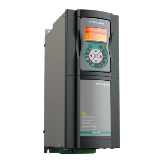
Page 66: Use Of The Keypad
6 - Use of the keypad This chapter describes the keypad and methods of use for display and program- ming of inverter parameters. 6.1 Description LCD display led is lit 7 virtual leds line: ILim led is off 01 MONITOR 02 DRIVE INFO Four alphanumeric lines 03 STARTUP WIZARD... -
Page 67: Navigation
LED’s meaning: the LED is lit, when the drive operates with a positive torque the LED is lit, when the drive operates with a negative torque the LED is lit, when the drive is enabled The led is lit when the drive is in local mode and OFF when in remote mode. -
Page 68: Scanning Of The Parameters
Description of the parameter. Depends on the type of parameter: ● Numeric parameter: displays the numeric value of the parameter, in the format required, and unit of measurement (figure A). ● Binary selection: the parameter may assume only 2 states, indicated as OFF-ON or 0 - 1 (figure B). -
Page 69: Parameter Modification
This function permits access to any parameter entering only the software number of the parameter (PAR). When the parameter reached by the “Goto” command is displayed, it is possible to navigate all the parameters forming part of the same group using the ▲ and ▼ keys. -
Page 70: How To Save Parameters
● LINK type parameter The parameter may assume the number of another parameter as value. ILim 0 5 . 0 4 PA R : 6 1 0 Ram ref 1 src Analo g in p ut 2 mon Value: 1550 ILim ILim ILim... -
Page 71: Configuration Of The Display
6.5 Configuration of the display 6.5.1 Language selection Menu 04 DRIVE CONFIG, parameter 04.15 Language select, PAR: 578, default=English. Used to set one of the languages available : English, Italian, Francais, Deutsch, Polish, Romanian, Russian, Turkish and Portuguese. ILim ILim ILim 0 4 . -
Page 72: Alarms
Menu 04 DRIVE CONFIG, parameter 04.16 Display backlight, PAR : 576. Sets lighting of the display the light of the display remains always on. (default) the light switches off after approx. 3 minutes from pressing of the last key. 6.6 Alarms The alarms page is displayed automatically when an alarm occurs. -
Page 73: Saving And Recovery Of New Parameter Settings
ILim Message Load default Code: 0001H-1 Press ESC to exit MESSAGE : identifies a message. xx indicate show many messages are enqueued. The queue may contain a maximum of 10 messages and the message with the highest number is the most recent. -
Page 74: Load Parameters From Keypad
If an error occurs during transfer, the following message is displayed: ILim Message Save par failed Code: Press ESC to exit paragraph 8.2. The code XX indicates the type of error, see To exit from the error message, press the ESC key. 6.8.3 Load parameters from keypad Menu 04 DRIVE CONFIG, parameter 04.20 Load par from keypad, PAR : 592. -
Page 75: Commissioning Via Keypad (Startup Wizard)
7 - Commissioning via keypad (STARTUP WIZARD) Adjustable frequency drives are electrical apparatus for use in industrial installations. Parts of the Drives are energized during operation. The electrical installation and the opening of the device should therefore only be carried out by qualified personnel. Im- Warning! proper installation of motors or Drives may therefore cause the failure of the device as well as serious injury to persons or material damage. - Page 76 the Americas, but may need to be considered in equipment being shipped to Europe. Selon les normes EEC, les drives ADV et leurs accessoires doivent être employés seule- ment après avoir verifié que la machine ait été produit avec les même dispositifs de sécurité demandés par la réglementation 89/392/EEC concernant le secteur de l’industrie.
- Page 77 Protect the device from impermissible environmental conditions (temperature, humidity, shock etc.). Protéger l’appareil contre des effets extérieurs non permis (température, humidité, chocs etc.). Caution To the output of the drive (terminals U, V, W) : - no voltage should be connected to the output of the drive - the parallel connection of several drives are not permissible.
-
Page 78: Startup Wizard
7.1 Startup Wizard 7.1.1 Startup Wizard for Asynchronous Motors Introduction The ADV200 can operate with regulation modes : V/f control (Voltage/Frequency) , Flux vector OL (open loop) and Flux vector CL (field-oriented control, closed loop). Menu 04 DRIVE CONFIG, parameter 04.2 Regulation mode, PAR: 552, default=V/f control. - Page 79 Step 1 - Connections Connect the drive to the power supply as illustrated in the following diagrams: Connection to the mains and motor L1 L2 L3 BR1 BR2 C 3 ph (3ph - 400 V / 460 V 50/60 Hz) “5.1.6 Power line For ADV-...-DC versions please refer to the diagrams in paragraph connection”, page 33...
- Page 80 Checks to be performed before powering the drive • Check that the supply voltage is correct (TN,TT for ADV200 standard series ; IT for ADV200...-IT series) and that the input terminals on the drive (L1, L2 and L3 or C and D for ADV-...-DC) are connected correctly. •...
- Page 81 Step 2 - Setting motor parameter (Set motor data) Set the rating data of the motor connected: rated voltage, rated frequency, rated current, rated speed, rated power, power factor (cosφ). Motor & Co. Type: ABCDE IEC 34-1 / VDE 0530 Motor: 3 phase 12345-91 50 Hz...
- Page 82 f = motor rated frequency (menu 16 MOTOR DATA par. 2006) nN = motor rated speed (menu 16 MOTOR DATA par. 2004) Rated power [kW]: motor rated power, for a motor rating plate with a HP power value, set the rated power kW = 0.736 x motor power Hp value.
- Page 83 Note ! At the end of the self-tuning procedure there is a request to open the Enable contact (terminals 7 – S3); the Take tune parameters command (menu 16 MOTOR DATA, PAR: 2078) is automatically executed. The calculated parameters are saved in a RAM memory to enable the drive to perform the neces- sary calculations.
- Page 84 Step 4 - Setting the maximum speed reference value (Set max speed) This step is used to define the maximum motor speed value that can be reached with each single reference signal (analog or digital). ILim ILim ILim ILim S E Q . 0 1 PA R : 6 8 0 S E Q .
- Page 85 Step 7 - Speed regulation setting In this step the basic settings in order to perform a functional test of the drive- motor system are described. This functional test uses factory settings as far as the analog and digital commands of the drive are concerned. The regulation mode is that set in PAR 552 Regulation mode, default is V/f control.
- Page 86 8. If the motor does not reach its maximum speed, self-tuning of the analog input may be necessary‘: set the input signal to its maximum value and set the An inp 1 gain tune parameter (PAR: 1508) to 1. 9. If the motor still rotates with a reference of zero, eliminate the condition by self-tuning the analog input offset: set the input signal to its minimum value and set 1 for An inp 1 offset tune (PAR: 1506).
- Page 87 Step 8 - Setting the motor in “Flux Vect OL” mode (sensorless) Menu 04 DRIVE CONFIG, parameter 04.2 Regulation mode, PAR: 552, set = [1] Flux vector OL. Test with no load applied to the motor Set the value of PAR 2308 OverFlux perc to 120%. 2.
-
Page 88: Startup Wizard For Synchronous Motors
7.1.2 Startup Wizard for Synchronous Motors Introduction The ADV200 can operate with regulation modes: field-oriented vector control Flux vector CL and Flux vector OL of permanent magnet synchronous motors (brushless). Note! Before starting, check the factory setting: Menu 04 DRIVE CONFIG, parameter 04.2 Regulation mode, PAR: 552, default=Flux vector CL. - Page 89 Step 1 - Connections “5.1.6 Power For ADV-...-4-DC versions please refer to the diagrams in paragraph line connection”, page 33 “5.1.8 Motor connection”, page Connect the drive to the power supply as illustrated in the following diagrams: Connection to the mains and motor L1 L2 L3 BR1 BR2 C 3 ph (3ph - 400 V...
- Page 90 Checks to be performed before powering the drive • Check that the supply voltage is correct (TN,TT for ADV200 standard series; IT for ADV200...-IT series) and that the input terminals on the drive (L1, L2 and L3 or C and D for ADV-...-DC) are connected correctly. •...
- Page 91 Step 2 - Setting motor parameter (Set motor data) Set the rating data of the motor connected. The self-tuning procedure is described below using the data of an imaginary motor by way of example. Rated Voltage [V]: motor rated voltage as indicated on the data plate. Rated current [A]: motor rated current, approximately, the value should not be less than 0.3 times the rated current of the drive, output current class 1 @ 400V on the rating plate of the drive.
- Page 92 Step 3 - Autotune of the motor The drive carries out the motor autotune procedure (real measurement of motor parameters). Autotune may last a few minutes. Note ! If this operation generates an error message (example Error code 1), check the connections of the Step 1 Step 2 power and control circuits (see...
- Page 93 Note ! Autotuning can be cancelled at any time by pressing ILim ILim ILim ILim ILim S E Q . 0 1 PA R : 2 0 2 4 STARTUP WIZARD STARTUP WIZARD Autotune STARTUP WIZARD Run autotune still ? Close Enable input Autotune still Open Enable input...
- Page 94 PAR: 552, default=Flux vector CL). Note! This procedure can be avoided if “SBM” series motors (supplied by Gefran) are used. The drives have a command to start automatic phasing of the encoder. This proce- dure can be run with the motor shaft in rotation and with the shaft stopped (the brake must be blocked).
- Page 95 Step 6 - Setting the maximum speed reference value (Set max speed) This step is used to define the maximum motor speed value that can be reached with each single reference signal (analog or digital). ILim ILim ILim ILim S E Q . 0 1 PA R : 6 8 0 S E Q .
- Page 96 Step 9 – Setting the synchronous motor in “Flux Vect OL” mode (sensorless) for a typically variable torque-type load with OL control Menu 04 CONFIG DRIVE, parameter 04.2 Regulation mode, PAR: 552, set = [1] Flux vector OL . Test with no load applied to the motor 1.
- Page 97 ILim ILim ILim 2 1 . 0 7 PA R : 7 0 2 0 2 1 . 0 7 PA R : 7 0 2 0 18 SPEED REG GAINS SLS id sel ctrl SLS id sel ctrl 19 REGULATOR PARAM Normal Advanced 20 TORQUE CONFIG...
-
Page 98: First Customized Start-Up
7.2 First customized start-up In this section a startup test is performed, using a standard configuration, to check drive functioning and command connections. A programming sequence has to be run to achieve a first simple customisation in order to be able to set the drive for the requested application. Note ! The main sections to be used, depending on the desired configuration, are described below. - Page 99 • Selecting the type of reference After setting the regulation mode, the source of the speed reference must be set in the Ramp ref 1 src parameter (05 REFERENCES menu, PAR: 610). This source can be selected from among those listed in the L_MLTREF selection list: Analog input 1 mon parameter (PAR: 1500) to use the signal applied to terminals 1 –...
- Page 100 Also in this case the ramps can be set in the Acceleration time 0 parameter (06 - RAMPS menu, PAR: 700) and Deceleration time 0 parameter (PAR: 702) parameters. • Motor potentiometer To use the motor potentiometer, the signals to increase or decrease the reference must be defined: set the Mpot up src parameter (08 - MOTOPOTENTIOMETER menu, PAR: 884) and Mpot down src parameter (PAR: 886) parameters respec- tively to increase and decrease the reference using selection list L_DIGSEL2.
- Page 101 Signals for the digital outputs can be programmed using the Digital output 1...4 src parameters (13 - DIGITAL OUTPUTS menu, PAR: from 1310 to 1316) using the settings in the L_DIGSEL1 selection list. The drive also includes two analog outputs which are not factory-set. These outputs must be enabled by setting Analog out 1 src (15 - ANALOG OUTPUTS menu, PAR: 1800) and Analog out 2 src parameters (PAR: 1802) with a signal selected from selection list L_ANOUT.
- Page 102 displays the motor temperature in °C (if KTY84 is selected). On the ALARM CONFIG menu, the MotorOT mon parameter (PAR 4536) • displays sensor resistance in ohms or °C. • On the ANALOG INPUTS menu, the Analog inp 1 filter parameter (PAR 1510) or Analog inp 2 filter parameter (PAR 1560) can be used to filter the resistance and temperature measurements.
- Page 103 Setting of the brake opening speed threshold Based on customer 22.13.4 3176 Brake open spd thr value application Setting of the brake closing speed threshold Based on customer 22.13.5 3178 Brake close spd thr value application Selection of the type of comparison between Torque ref% 22.13.6 3182...
- Page 104 • Keypad Use the LOC / REM key with the Enable input open (terminal 7 on terminal strip T2) to control running, to stop and reverse the direction of rotation of the motor using the operator keypad on the drive. Use the potentiometer or an analog signal to control speed.
-
Page 105: For Synchronous Motors, Flux Vector Cl And Flux Vector Ol Control
7.2.2 For Synchronous Motors, Flux vector CL and Flux vector OL control Note ! At start-up, the synchronous motor may turn slightly in the direction opposite to that of rotation. This may depend on the parameter settings, the position of the rotor and the inertia/load applied. •... - Page 106 log inp 1 type parameter (14 - ANALOG INPUTS menu, PAR.1502): ± 10V 0-20mA o 0-10V 4-20mA As well as programming the Analog inp 1 type parameter (PAR:1502) you must also verify the position of the switches on the regulation card, as showed on chapter 5.2.4.
- Page 107 Speed ref top lim (PAR: 670). Upper speed limit: the maximum setting is 200% of the Full scale speed. Speed ref bottom lim (PAR: 672). Lower speed limit: the maximum setting is -200% of the Full scale speed. Overspeed threshold (24 - ALARM CONFIG menu, PAR: 4540). Overspeed alarm limit.
- Page 108 • Setting an analog output for reading a temperature sensor Analog input 1 Analog output 1 Analog input 2 Analog output 2 The following is a description of the commissioning procedure to use the drive’s ADV200 regulation card to acquire the temperature of a motor with KTY84 / PTC sensors: •...
- Page 109 tor starts the acceleration ramp and moves to the speed set in the FWD direction. With the motor running you can adjust the speed using the PAR 602 Dig ramp ref 2 (or PAR 604 Dig ramp ref 3, in this case modify also the selection PAR 614 Ramp ref 3 src to PAR 604 Dig ramp ref 3) and the acceleration/deceleration ramps using Acceleration time 0 (PAR: 700) and Deceleration time 0 (PAR: 702).
-
Page 110: Programming
7.3 Programming 7.3.1 Menu display modes The programming menu can be displayed in two modes, which can be selected using the Access mode parameter (04 - DRIVE CONFIG menu), see chapter 6.5.2: • Easy (default) only the main parameters are displayed. •... -
Page 111: Variable Interconnections Mode
7.3.3 Variable interconnections mode The source (src) allows the desired control signal to be assigned to the function block input. This operation is performed by using specific selection lists. Possible control signal sources: 1 – Physical terminal The analog and digital signals come from the terminal strip of the regulation card and/or from those of the expansion cards. - Page 112 * -1 Terminal input Analog input 1 Block Analog input 1 mon * +1 An inp 1 alt value An inp 1 sign src Null Null An inp 1 alt sel src Ramp Setpoint Block Ramp ref 1 src Ramp ref 1 mon Ramp ref invert src Null The diagrams above illustrate the internal processing philosophy of the single...
-
Page 113: Multiple Destination
7.3.4 Multiple destination Several functions can be assigned together to each input: to display which and how many functions have been assigned to each input, check the relative “dest” parameter to see whether there is a number shown in square brackets to the right of the number of the selected parameter (as shown in the figure below). -
Page 114: Troubleshooting
8 - Troubleshooting 8.1 Alarms Note ! paragraph 6.6.1. To reset alarms, see In the following table, the Code is visible only from serial line. Code Error message shown Sub-code Description on the display No alarm Condition: No alarm present Condition: DC link overvoltage alarm due to energy recovered from the motor. - Page 115 HeatsinkS OTUT Condition: IGBT modules temperature too high or too low alarm Solution: - Verify the correct operation of the cooling fan. - Check that the heatsinks are not clogged - Check that the openings for the cabinet cooling air are not blocked. Condition: Intake drive air temperature too high alarm.
- Page 116 Condition: Speed feedback loss alarm. The encoder is not connected, not connected properly or not powered: verify encoder operation Speed fbk loss by selecting the PAR 260 Motor speed parameter in the MONITOR menu. Solution: - Check encoder wiring for integrity. - Check that the encoder is connected to the power supply.
- Page 117 Condition: Enabled application developed in the IEC 61131-3 environment has found the condi- Plc1 fault 33 ... tions for generating this specific alarm to be true. The meaning of the alarm depends on the type of application. For more information, refer to the documentation concerning the specific Plc8 fault application..
- Page 118 The information received from the encoder is not reliable Solution: Contact Gefran in order to update the firmware on the optional encoder card. Condition: this may occur when powering the drive if an expansion card has been removed or replaced or the incorrect enable key is inserted for a given firmware function.
-
Page 119: Speed Fbk Loss Alarm According To The Type Of Feedback
Condition: Enabled application developed in the IEC 61131-3 environment has found the condi- tions for generating this specific alarm to be true. The meaning of the alarm depends on the type of application. For more information, refer to the documentation concerning the specific Plc9 fault 53 ... - Page 120 below: D7..D4 Value For each D0, D1, D2, D3 value other than 0x0 search for the sub-values it can be divided into in table 1. D0 D1 D2 D3 For each D0, D1, D2, D3 value other than 0x0 search for the sub-values it can be divided into in table 1.
- Page 121 Value Description Name D7..D4 Solution: Check the connection of the encoder-drive channel B, check the connection of the screen, check the Encoder 1 supply voltage. Check parameters 2102 Encoder 1 supply and 2104 Encoder 1 input cfg (if encoder 1 is used). Check parameters 5102 Encoder 2 supply and 5104 Encoder 2 input cfg (if encoder 2 is used).
- Page 122 Value Description Name D7..D4 Solution: Check the connection of the the encoder-drive channels A-B, check the connection of the screen, check the encoder supply voltage, check parameter 2102 Encoder 1 supply, check parameter 2108 Encoder 1 signal Vpp. CRC_CKS_P Cause: SSI signals not present or disturbed. Solution: Check the connection of the clock and encoder-drive data, check the connection of the screen, check the encoder supply volt- age, check parameter 2102 Encoder 1 supply, check parameter 2112...
- Page 123 Value Description Name D7..D4 Signal amplitude Erroneous (1) Position value Erroneous (1) Over voltage Yes (1) Under voltage Under voltage supply (1) Over current Yes (1) Battery Change the battery (2) 7..15 (1) Can also be set after the power supply is switched off or on. (2) Only for battery-buffered encoders Speed fbk loss [22] alarm with Hiperface absolute encoder ●...
- Page 124 Value Description Name D7..D4 Checksum of transmitted data is wrong Incorrect command code Wrong number of transmitted data Illegal transmitted command argument Wrong access authorization specified Selected field has READ ONLY status Data field (re) definition not executable due to field size Specified address is not available in selected field Selected field does not yet exist...
- Page 125 Cause: Firmware on option card incompatible with firmware on Compatibility regulation card. error When this has been signalled the information obtained from the encoder is not reliable. Solution: Contact Gefran in order to update the firmware on the optional card. ADV200 • Quick start up guide...
-
Page 126: Extio Fault" Alarm
8.1.2 “ExtIO fault” Alarm The drive may generate an “ExtIO fault” alarm for a series of reasons. At drive startup there may be problems with configuration, associated with the EXP-FL- XCAN-ADV card or parameter settings. During the Config phase the alarm might depend on an SDO communication error. -
Page 127: Fastlink" Alarm
Cause: The firmware on the optional FastLink card is incompatible with that on the Compatibil- regulation card. ity error Solution: Contact Gefran in order to update the firmware on the optional FastLink card. Slave an- Cause: situation in which an interrogated Slave does not reply swer NOK Solution: check FastLink connection ADV200 •... -
Page 128: Messages
8.2 Messages Note ! chapter 6.7. For more information see Index Error message shown Sub-code Description on the display Condition: may occur during loading of the parameter database saved in flash normally appears in the following conditions: at initial power-on when a new firmware version is downloaded, when the regulation is installed on a new size, when the region is changed. - Page 129 Solution: Close the enable contact before sending the Autotune command Internal calculation error concerning IGBT control Solution: Perform autotuning once more, if the problem persists, contact the Gefran technical support centre. The drive has measured a stator resistance value exceeding the set limit.
- Page 130 Index Error message shown Sub-code Description on the display 0020H-32 The power card is configured for a drive that is incompatible with the regulation card 0021H-33 The configuration of the power card is not compatible with the regulation card 0017H-23 The configuration required is not available on the power card Solution: Download the correct configuration on the power card Save par failed...
- Page 131 0001H-1 Incorrect PLC key. PLC application not available. Solution: Ask Gefran to supply the correct key to enable the desired firmware function. Condition: this may occur at drive power-on if the incorrect enabling key was inserted for a given Key expiring firmware function.
- Page 132 The information received from the encoder is not reliable Solution: Contact Gefran in order to update the firmware on the optional encoder card. Condition: this may occur when powering the drive if an expansion card has been removed or Options cfg changed replaced or the incorrect enable key is inserted for a given firmware function.
-
Page 133: Other Anomalies
Index Error message shown Sub-code Description on the display Incremental encoder impulse count sign inverted with respect to the absolute encoder impulse count. Solution: Invert the A+ and A- signal of the incremental encoder. Incremental encoder impulse count sign inverted with respect to the absolute encoder impulse count. -
Page 134: Specification
9 - Specification 9.1 Environmental Conditions Installation location ������������������Pollution degree 2 or lower (free from direct sunligth, vi- bration, dust, corrosive or inflammable gases, fog, vapour oil and dripped water, avoid saline environment) Installation altitude ������������������Max 2000m (6562 feet) above sea level (up to 1000m without current derating). -
Page 135: Speed Control
Loop sampling time �������������������125µs Response time ����������������������600 - 1600µs PWM frequency ���������������������2, 4, 6, 8, 10, 12 kHz (size dependent) 9.3.2 Speed control Type ������������������������������Flux vector CL (Field Oriented Control with feedback) and Flux vector OL (Open Loop Field Oriented Control) Loop sampling time �������������������125µs Response time ����������������������5 - 10ms Speed measurement ������������������FP, F mode... -
Page 136: Initial Torque Limit
Band width �������������������������< 100Hz (Flux vector CL), <10Hz (Flux vector OL) Control range �����������������������1:1,5 of Rated speed (5). The flux reduction range depends on the type of motor. Please contact Gefran for further details. 9.5 DC circuit Overvoltage threshold (Overvoltage) ������820 V Undervoltage threshold (Undervoltage) ����390 V... -
Page 137: Input Electrical Data
9.6 Input electrical data 9.6.1 AC power supply AC Input voltage, U �����������������3 ph 380 V -15% ... 500 V +5%, AC Input frequency �������������������50/60 Hz, ± 5% Choke �����������������������������integrated (DC) up to size 61320 Total harmonic distortion (THD) ���������40% Light duty, 50% Heavy duty (at nominal current) Connection to TT and TN Networks �������yes, standard version Connection to IT Networks �������������yes, special version ADV200...-IT only (upon request). -
Page 138: Dc Power Supply
3 x 780 1 MW 3 x 780 3 x 850 (*) RMS input current in case of power from 6 impulse bridge. Nota! Contact Gefran if an AFE200 series regenerative power supply is used. ADV200 • Quick start up guide... -
Page 139: Output Electrical Data
9.7 Output electrical data U2 Max output voltage ����������������0,94 x U =AC Input voltage) f2 Max output frequency ���������������500 Hz (Sizes 1007 ... 72000) , 200 Hz (≥ Size 72500): see section 9.3.3 for more details. Braking IGBT Unit ��������������������KBX models: standard internal with external resistor, KXX: not included;... - Page 140 Rated output current Rated output current (For Asynchronous motors) (For Synchronous motors) =400Vac =460Vac =400Vac =460Vac Sizes Heavy duty Light duty Heavy duty Light duty Heavy duty Light duty Heavy duty Light duty 1007 1015 1022 1030 1040 11.7 11.7 10.5 2055 16.5...
-
Page 141: Derating Factors
Rated output current Rated output current (For Asynchronous motors) (For Synchronous motors) Sizes ADV200-DC @540 Vdc @540 Vdc @650 Vdc @650 Vdc @540 Vdc @540 Vdc @650 Vdc @650 Vdc Heavy duty Light duty Heavy duty Light duty Heavy duty Light duty Heavy duty Light duty... - Page 142 Derating factor Kv =400Vac =460...480Vac Sizes from AFE200 from aFE200 Tamb = 40°C Tamb ≤ 30°C Tamb = 40°C Tamb ≤ 30°C Tamb 31 ... 40°C Tamb ≤ 30°C Tamb 31 ... 40°C 1007 ... 1 MW 0.81 Derating factor Switching frequency Sizes Default...
- Page 143 Output Current derating factor at Ambient Temperature of: Installation altitude above sea level 20°C 25°C 30°C 35°C 40°C 45°C 50°C 0 … 1000 m 0.95 0.90 Input voltage derating factor : Derating factor of the input voltage based on altitudes Figure 9.7.1: K derating factor based on altitudes 1000...
-
Page 144: Overload For Output Frequency
9.7.2 Overload for output frequency For Asynchronous motors Heavy duty Light duty Sizes K1 SP [%] K2 SP [Hz] K3 SP [Hz] K1 SL [%] K2 SL [Hz] 1007 1015 1022 1030 1040 2055 2075 2110 3150 3185 3220 4300 4370 4450 5550... -
Page 145: Voltage Level Of The Inverter For Safe Operations
For Synchronous motors Heavy duty Light duty Sizes K1 SP [%] K2 SP [Hz] K3 SP [Hz] K1 SL [%] K2 SL [Hz] 2075 2110 3150 3185 3220 4300 4370 4450 5550 5750 5900 61100 61320 71600 72000 72500 73150 73551 400 kW 500 kW... -
Page 146: Cooling
9.9 Cooling All the Drives have internal fans. Airflow of fan Dissipated power Sizes Heatsink (m Internal (m 1007 1015 1022 1030 1040 2055 2075 56 x 2 2110 56 x 2 3150 80 x 2 3185 80 x 2 3220 80 x 2 4300... -
Page 147: Weight And Dimensions
9.10 Weight and dimensions Sizes Weight (kg) Weight (lbs) Sizes Weight (kg) Weight (lbs) ADV200-...-4 ADV200-...-4-DC 1007 ... 1040 12.8 2055 ... 2110 10.2 22.5 3150 ... 3185 16.4 36.2 3185 26.5 3220 48.5 3220 39.7 4300 ... 4450 70.6 4300 ... - Page 148 118 mm (4.65”) 100 [3.94”] 82 mm (3.23”) Figure 9.10.1: Size 1 Dimensions 150 mm (5.91”) 120 [4.72”] 110 mm (4.33”) Figure 9.10.2: Size 2 dimensions ADV200 • Quick start up guide...
- Page 149 180 mm (7.09”) 150 [5.91”] 135 mm (5.31”) Figure 9.10.3: Size 3 dimensions (ADV200-...-4) 180 mm (7.09”) 150 [5.91”] Figure 9.10.4: Size 3 dimensions (ADV200-...-4-DC) ADV200 • Quick start up guide...
- Page 150 268 [10.55”] Figure 9.10.5: Size 4 dimensions (ADV200-...-4) 268 [10.55”] Figure 9.10.6: Size 4 dimensions (ADV200-...-4-DC) ADV200 • Quick start up guide...
- Page 151 311 [12.24”] 220 [8.66”] 265 [10.43”] 279 [10.98”] Figure 9.10.7: Size 5 dimensions (ADV200-...-4) 311 [12.24] 325 [12.80] 45.5 190 [7.48] DETAIL DETAIL SCALE 1:1 DETAIL DETAIL 265 [10.43] SCALE 1:1 Figure 9.10.8: Size 5 dimensions (ADV200-...-4-DC) ADV200 • Quick start up guide...
- Page 152 422 [16.61”] 350 [13.78”] 175 [6.89”] Figure 9.10.9: Size 6 dimensions (ADV200-...-4) 421 [16.57”] 360 [14.17”] 275 [10.83”] 175 [6.89”] 350 [13.78”] Figure 9.10.10: Size ADV61110-...-DC dimensions ADV200 • Quick start up guide...
- Page 153 421 [16.57”] 360 [14.17”] 275 [10.83”] 175 [6.89”] 350 [13.78”] Figure 9.10.11: Size ADV61320...-DC dimensions 355.6 (16.4) (14.0) 177.8 Vista senza protezioni (*) Protezione in policarbonato trasparente View without protections (*) Protective trasparent policarbonate (19.1) Figure 9.10.12: Size 7 dimensions ADV200 •...
- Page 154 [33.0] Quote senza protezioni vedere taglia 7 See Size 7 for dimensions without protections. (*) Protezione in policarbonato trasparente (*) Protective trasparent policarbonate (Optional BARS KIT) [19.1] 177.8 177.8 Figure 9.10.13: Sizes 400 ... 710 kW dimensions ADV200 • Quick start up guide...
- Page 155 1257 [49.49] (*) Protezione in policarbonato trasparente (*) Protective trasparent policarbonate Quote senza protezioni vedere taglia 7 See Size 7 for dimensions without protections. (Optional BARS KIT) [19.1] 177.8 Figure 9.10.14: Sizes 900 kW - 1 MW dimensions ADV200 • Quick start up guide...
-
Page 156: Options
10 - Options 10.1 Optional external fuses 10.1.1 AC input side fuses (F1) The inverter must be fused on the AC Input side. Use fast fuses only. F1 - AC input side fuses DC link EUROPE AMERICA Sizes capacitors Type Code Type Code... -
Page 157: External Fuses Of The Power Section Dc Input Side (F2)
10.1.2 External fuses of the power section DC input side (F2) The following fuses must be used with an external DC power supply or regenerative converter (for further details refer to the converter instruction manual): F2 - External fuses for DC input side Sizes EUROPE AMERICA... -
Page 158: Optional Internal Fuses For The Dc Connection (F2)
10.1.3 Optional internal fuses for the DC connection (F2) F2 - External fuses for DC input side Sizes EUROPE, AMERICA Type Code 71600 20 623 32.500 / 170M5160 S8B21BF 72000 20 623 32.630 / 170M5162 S8B22BF 72500 20 623 32.800 / 170M5164 S8B23BF 73150 - 73551 20 623 32.1000 / 170M5166... -
Page 159: Choke
Use of mains chokes with an impedance of at least 3% is recommended. The table below shows the minimum inductance values and current ratings with the codes proposed by Gefran. In case of a Master and Slave connection (400 kW to 1 MW devices) the use of... - Page 160 The ADV200 drive can be used with general purpose standard motors or with motors specially designed for drive use. The latter usually have a higher isolation rating to better withstand PWM voltage. Examples of reference regulations are provided below: Motors designed for use with Adjustable Frequency Drives do not require any spe- cific filtering of the voltage waveform from the drive.
- Page 161 Sizes 400 kW ... 1 MW The use of output chokes is mandatory for for parallel units; as a function of the application/connec- tion, according to the following criteria: • for applications with short motor cables (≤ 100 m long) bus bars with an integrated ferrites (see Table 1) or Only Ferrites may be used (see Table 2) or single distributor chokes may be used (see Table 3);...
- Page 162 Table 2: Ferrites Motor cable lenght distance ≤ 100 m @400Vac … 460Vac Inverter Sizes output Dimensions (mm) Weights Q.ty (*) Type Code Ferrite -N 57L 34P 22H t1.6 400 kW SP / SL 500 kW SP / SL 630 kW SP / SL 11.5 S7DDV...
- Page 163 Table 4: output choke Motor cable lenght distance > 100 m Inverter @400Vac … 460Vac Sizes output Type Code Q.ty Dimensions and Weights ADV-72000-KXX-4-MS 04 W x H x d: 300 x 270 x 230 mm 400 kW LU3-200 S7AF0 33 kg ADV-72000-XXX-4-SL ADV-72000-KXX-4-MS 04...
-
Page 164: External Emc Filter (Optional)
10.3 External EMC filter (optional) ADV200 series inverters (except ADV200-...-DC models) are equipped with an internal EMI filter able to guarantee the performance levels required by EN 61800- 3 standard (according to 2nd environment, category C3) with a maximum of 20 meters of shielded motor cable (up to 50 metres for size 5 and above). - Page 165 AC mains voltage 400V -15% … 480V +10% Heavy duty Light duty EN 61800-3 : Sizes Category / Environment Type Code Type Code / Motor cable length ADV-73551-KXX-4-MS 07 EMI-480-800 S7DGM EMI-480-800 S7DGM C3 / 2nd / 100 m 710 kW ADV-73551-XXX-4-SL EMI-480-800 S7DGM...
-
Page 166: External Filters To Reduce Grid Harmonics (Optional)
10.4 External filters to reduce grid harmonics (optional) ADV200-RHF filters are used to reduce total harmonic distortion (current) on the power supply line. The choice of filter depends on the rated characteristics of the motor, on its ser- vice conditions (LD or HD), and on the performance levels you want to achieve in terms of line THDi. -
Page 167: Connection Diagrams
Calculation of filter current I filter [A] = Uln * √3 * ηf * ηl * ηm Example: Rated motor power Pm 18.5 [kW] Motor efficiency ηm Mains voltage Uln 400 [V] Mains frequency 50 [Hz] Inverter efficiency ηl Passive filter efficiency ηf 99.0% Filter current 29.0 [A]... - Page 168 Figura 10.4.2: Parallel connection of RHF-A-... and RHF-B-... models RHF-A/B-... RHF-A/B-... X2.1 X2.2 X2.3 X2.1 X2.2 X2.3 Auxiliary circuit (Pulse lock) ADV200 K2M = Capacitor disconnect (optional) Figura 10.4.2: RHF-AS-... and RHF-BS-... models 230Vac,1ph RHF-AS/BS-... RHF-R* Fan supply X4.1 X4.2 X4.3 Auxiliary circuit (Pulse lock) ADV200...
-
Page 169: Matching Motors, Rhf Filters And Adv200 Drives
10.4.3 Matching motors, RHF filters and ADV200 drives Grid: 380V / 50Hz Drive Output: Light Duty RHF Passive Filter Line Input Motor Motor Drive Current Power 4 Rated Rated Efficiency Size Overload Type (1) Current @ 380V poles IE2 Power Current [kW] 82.8... - Page 170 Grid: 400 - 415V / 50Hz Drive Output: Light Duty Line Input RHF Passive Filter Motor Drive Motor Current Rated Rated Efficiency Size Power 4 Overload Type (1) Current @ 400V Power Current poles IE2 [kW] 18,5 91,2 3150 18,5 RHF-A/B 29-400-50-20-A 30,3 91,6...
- Page 171 Grid: 380V / 60Hz Drive Output: Light Duty RHF Passive Filter Line Motor Motor Power Drive Size Input Current Rated Rated Efficiency 4 poles IE2 Overload Type (1) Current @ 380V Power Current [kW] 94.7 61100 RHF-A/B 217-380-60-20-A 217.0 219.4 94.9 61320 RHF-A/B 252-380-60-20-A...
-
Page 172: Dimensions And Weights Of Rhf Filters
Grid: 460V / 60Hz - Motor voltage: 460V Drive Output: Light Duty RHF Passive Filter Line Motor Motor Power Drive Size Input Current Rated Rated Efficiency 4 poles IE2 Overload Type (1) Current @ 380V Power Current [kW] 96.5 630 kW 1107 On request 96.7... -
Page 173: Dimensions And Weights Of L0-Rhf Chokes
10.4.5 Dimensions and weights of L0-RHF chokes L0-RHF-AS/BS mais chokes are included in delivery of the RHF-AS/BS module filters series (RHF-AS/BS = L0 RHF-AS/BS choke + n filters RHF-R). L0 RHF-AS/BS Dimensions: W * H * d (mm) Weight (kg) External choke L0-RHF-AS 480-400-50-230-A 420 * 370 * 325... -
Page 174: Braking Resistor (Optional)
10.5 Braking resistor (optional) Recommended resistors for use with internal braking unit (except ADV200-DC models): List and technical data of standard external resistors Max Overload Max Overload Braking resis- Resistance Sizes energy, 1”- duty- energy, 30”- duty- tor nominal value Resistor type Code Enclosure... -
Page 175: Installation Of Optional Cards
10.6 Installation of optional cards Up to three optional cards can be inserted in the three slots under the top cover: • Slot 1 : dedicated to IO cards (EXP-IO-...-ADV , EXP-FL-XCAN-ADV) • Slot 2: dedicated to Encoder cards (EXP-...-ADV) and I/O cards •... -
Page 176: Slot / Encoder Card Management
10.6.1 SLOT / Encoder Card Management Configurations other than those described below are not allowed. Attention Note ! Encoder 1 = Encoder menu, parameters 21XX. Encoder 2 = Encoder menu, parameters 51XX. Encoder 3 = Encoder menu, parameters 52XX. 1 encoder managed (one optional card) Optional Card SLOT Software recognition... - Page 177 3 encoders managed (two optional cards) Optional Card SLOT Software recognition Optional Card SLOT Software recognition EXP-DE-I1R1F2-ADV EXP-SE-I1R1F2-ADV EXP-SESC-I1R1F2-ADV EXP-EN/SSI-I1R1F2-ADV Encoder 1 EXP-DE-I2R1F2-ADV Encoder 2 / Encoder 3 (o slot 3 EXP-HIP-I1R1F2-ADV EXP-ASC-I1-ADV EXP-RES-I1R1-ADV 3-encoder managed (three optional cards) Prohibited combination. ADV200 •...
-
Page 178: Procedure
10.6.2 Procedure paragraph 5.2.1. 1. Remove the bottom cover as indicated in 2. To remove the top cover, loosen screws B by about 2 turns and slide out cover C as shown in the figure. 3. To prevent damage to the connection of the keypad, the top cover can be positioned as indicated in the figure. -
Page 179: Shielding Of Optional Card Connections
4. Position and fasten the metallic shield (S), provided with the optional card, with the screws S1 and S2 (x1) as shown in the figure. SLOT 1 5. Position the optional card in the dedicated Slot (in the example, the EXP-IO card is inserted in Slot 1). -
Page 180: Wiring Connection Using Sbm Motor Series
Following paragraphs specify the connection between the drive ADV200 and sen- sors feedback installed on SBM standard series synchronous motors. 10.7.1 Resolver wiring (RES) Following table shows the connections needed using Resolver sensor mounted on SBM5, SBM7, SBM8, SBM9 Gefran series motor: Resolver 19poles SBM motor connector EXP-RES-I1R1-ADV board... -
Page 181: Sinusoidal Encoder Sincos Wiring (Sesc)
10.7.2 Sinusoidal Encoder SinCos wiring (SESC) Following table shows the connections needed using SinCos encoder mounted on SBM5, SBM7, SBM8, SBM9 Gefran series motor (it cannot be applied those type of encoder with SBM3): SinCos 19poles SBM motor connector SBM5, SBM7, SBM8, SBM9... -
Page 182: Appendix 1 - Parallel Connection (400 Kw
Appendix 1 - Parallel connection (400 kW ... 1 MW sizes) A 1.1 Introduction To obtain a drive of more than 355 kW connect a number of single units of be- tween 200 kW and 355 kW in parallel. A parallel connection of several drives basically consists of one MASTER unit and one or more SLAVE units. - Page 183 The INT-SLAVE card is factory-set. In the event of a failure, the INT-P-ADV card may only be replaced by trained and specialized Gefran personnel. The drives mounting the INT-P-ADV cards rev L and higher, can not be connected in parallel with drives that mount the INT-P-ADV card rev F or lower.
-
Page 184: A 1.2 Ms-Sl Interface Cable Wiring Sizes 400
A 1.2 MS-SL interface cable wiring sizes 400...710 kW Fit the ADV200 MASTER and SLAVE inverters inside the electrical panel. Connect all the power section cables and connect the signal cable for interfacing between the 2 drives. The cable (code 8S860B) for connecting 2 drives is one metre long and has two quick coupling male MDR connectors at the ends. -
Page 185: A 1.3 Ms-Sl Interface Cable Wiring Sizes 900 Kw
A 1.3 MS-SL interface cable wiring sizes 900 kW ... 1 MW Fit the ADV200 MASTER and SLAVE inverters inside the electrical panel. Con- nect all the power section cables and connect the 2 signal cables for interfacing between the 3 drives. The cable (code 8S860B, x 2) for connecting the drives is one metre long and has two quick coupling male MDR connectors at the ends. -
Page 186: A 1.4 Jumpers And Switches
A 1.4 Jumpers and Switches INT-P-ADV (MASTER and SLAVE) cards The jumpers and switches on these cards are factory-set. DO NOT change these settings. A 1.5 LEDs The cards incorporate a LED diagnostics system for rapid analysis of everything happening on a multi-unit drive. INT-P-ADV (MASTER and SLAVE) cards INT-P-ADV (≥... - Page 187 LEDS Normal Colour FUNCTION functioning ≤ F (*) ≥ L (*) D127 It lights up to indicate overtemperature of the air inside the drive D132 IGBT U They light up to indicate loss of the feedback signal relating D130 IGBT V to the moment the IGBT devices are switched on.
-
Page 188: A 1.6 Safety Sto Interface
For instructions on connecting and commissioning the safety card with the SIL2 or SIL3 safety level function, please see chapter 7 “Application Examples” in the Safety manual (code 1S5F94) in the CD Caution supplied with the drive or which you can download from www.gefran.com. A 1.6.2 ADV-...-MS-SI models (INT-P-ADV card, from revision “L”) L1(*) The ADV200 size 7 (and parallel unit ADV-...-MS) does not have the EXP-SFTy-... - Page 189 For instructions on connecting and commissioning the safety card with the SIL2 or SIL3 safety level function, please see chapter 7 “Application Examples” in the STO Safety Interface manual (code 1S5F94) in the CD supplied with the drive or which you can download from www.gefran.com. TB1 terminal...
- Page 190 CONTROLLER ENABLE (SFTY ENABLE) FB2 Feedback (SAFETY ENABLE) OPEN OPEN Open Close In this way, when the (SFTy ENABLE) command is high, the control input pro- grammed as DRIVE INTERLOCK is also high and the drive can be enabled. Figure A1: Connection of safety terminals TB1 and TB2 on INT-P-ADV card R-ADV200 INT-P-ADV 1 2 3...
-
Page 191: Appendix 2 - Miscellaneous
900kW 75600 5550 4700 1 MW 75600 You cannot add an external on 1007 ... 61320 sizes. You can add an external capacitor from sizes 71600 and higher (ask Gefran for more details). Attention ADV200 • Quick start up guide... -
Page 192: A 2.2 Encoders
A 2.2 Encoders Encoders provide motor speed and position feedback The regulation algorithms in the ADV200 drive are capable of controlling asyn- chronous and permanent magnet synchronous (brushless) motors. The regulation algorithm may or may not use the speed measurement obtained from the encoder reading. - Page 193 Use this setting when the value in mechanical degrees of the distance of the rotor pole from the “zero” of the encoder is known. This value must be entered manually before starting the phasing (contact Gefran’s Customer Service for further informa- tion).
- Page 194 see chapter 8.2 Messages, is drive, one of the codes listed in Autotune (phasing), shown. Possible faults: - faults in electric signals not detected with a “Speed fbk loss [22]” alarm - error in the PAR 2008 Pole pairs parameter setting - error in the PAR 2100 Encoder pulses parameter setting Static phasing Using this method, in which the motor cannot move, the encoder and motor data...
-
Page 195: Appendix 3 - Adv200-Eh/Ehr Models
Appendix 3 - ADV200-EH/EHR models The following tables shows the electrical specifications of external heatsink drive models with IP54 protection degree. Although not shown, the previous chapters also apply to ADV200-EH/EHR mod- els. A3.1 Rated total power dissipated side card Dissipated power Sizes ADV200-EH-2075... - Page 196 Figure 3.2.1: Size 2 dimensions (ADV200-...-EH) 7 (8x) ADV200 • Quick start up guide...
- Page 197 Figure 3.2.2: Size 3 dimensions (ADV200-...-EH) 7 (x12) ADV200 • Quick start up guide...
- Page 198 Figure 3.2.3: Size 4 dimensions (ADV200-...-EH) 247.5 7 (8x) ADV200 • Quick start up guide...
- Page 199 Figure 3.2.4: Size 5 dimensions (ADV200-...-EH) 9 (8x) ADV200 • Quick start up guide...
- Page 200 Figure 3.2.5: Size 6 dimensions (ADV200-...-EH) STADIO 2 INSIDE BOX STADIO 1 EXTERNAL BOX 222.5 GASKET ADV200 • Quick start up guide...
- Page 201 Figure 3.2.6: Size 2 dimensions (ADV200-...-EHR) STADIO 2 INSIDE BOX STADIO 1 EXTERNAL BOX 7 (8x) GASKET ADV200 • Quick start up guide...
- Page 202 Figure 3.2.7: Size 3 dimensions (ADV200-...-EHR) STADIO 2 INSIDE BOX STADIO 1 EXTERNAL BOX 7 (x12) ADV200 • Quick start up guide...
- Page 203 Figure 3.2.8: Size 4 dimensions (ADV200-...-EHR) STADIO 2 INSIDE BOX STADIO 1 EXTERNAL BOX 247.5 GASKET ADV200 • Quick start up guide...
- Page 206 Ph. +44 (0) 8452 604555 Fax +91 20 6614 6501 Fax +44 (0) 8452 604556 gefran.india@gefran.in sales@gefran.co.uk SENSORMATE AG GEFRAN MIDDLE EAST ELEKTRIK VE GEFRAN INC. ELEKTRONIK SAN. VE TIC. LTD. STI Steigweg 8, 8 Lowell Avenue Yesilkoy Mah. Ataturk...