Sign In
Upload
Manuals
Brands
gefran Manuals
Controller
ADV200-...-DC Series
gefran ADV200-...-DC Series Manuals
Manuals and User Guides for gefran ADV200-...-DC Series. We have
3
gefran ADV200-...-DC Series manuals available for free PDF download: Quick Start Up Manual, Specification And Installation, Quick Start Up Manual
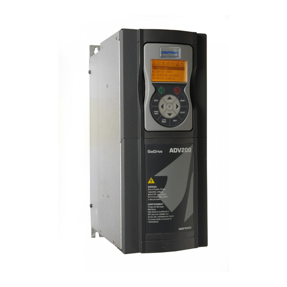
gefran ADV200-...-DC Series Quick Start Up Manual, Specification And Installation (206 pages)
Field oriented vector AC Drive for synchronous/asynchronous motors
Brand:
gefran
| Category:
Controller
| Size: 13.59 MB
Table of Contents
Information about this Manual
2
Table of Contents
3
1 Safety Precautions
6
Symbols Used in the Manual
6
Safety Precaution
7
General Warnings
7
Instruction for Compliance with UL Mark (UL Requirements), U.S. and Canadian Electrical Codes
9
2 Introduction to the Product
11
Drive Type Designation
12
Parallel Inverters
13
3 Transport and Storage
14
General
14
Permissible Environmental Conditions
15
Disposal of the Device
15
4 Mechanical Installation
16
Inclination and Mounting Clearance
16
Fastening Positions
17
5 Wiring Procedure
22
Power Section
26
Cable Cross Section
26
Connection of Shielding
28
EMC Guide Line
29
Block Diagram Power Section
30
Internal EMC Filter
32
Power Line Connection
33
Input Mains Choke (L1)
36
Motor Connection
37
Braking Unit Connection (Optional)
38
Parallel Connection on the AC (Input) and DC (Intermediate Circuit) Side of Several Inverters
39
Parallel DC Connection
40
Connection of Fans
41
Regulation Section
43
Removing the Terminal Cover
43
Cable Cross Section
43
Regulation Section Connection
43
Switches, Jumpers and LED
45
R-PSM Pre-Charge Card (Only for Sizes ≥ 71600)
48
R-SM3-ADV Pre-Charge Card (Only for Sizes ≥ 71600)
54
Braking
56
Braking Unit
56
Encoder
58
Serial Interface (XS Connector)
58
Drive / RS 485 Port (Not Insulated) Point-To-Point Connection
58
Drive / RS485 Port Point-To-Point Connection (with Insulation)
60
RS 485 Multi-Drop Connection
60
Typical Connection Diagrams
62
6 Use of the Keypad
66
Description
66
Navigation
67
Scanning of the First and Second Level Menus
67
Display of a Parameter
67
Scanning of the Parameters
68
List of the Last Parameters Modified
68
Goto Parameter" Function
68
Parameter Modification
69
How to Save Parameters
70
Configuration of the Display
71
Language Selection
71
Selection of Easy / Export Mode
71
Startup Display
71
Back-Lighting of the Display
71
Alarms
72
Alarm Reset
72
Messages
72
Saving and Recovery of New Parameter Settings
73
Selection of the Keypad Memory
73
Saving of Parameters on the Keypad
73
Load Parameters from Keypad
74
Transfer of Parameters between Drives
74
7 Commissioning Via Keypad (STARTUP WIZARD)
75
Startup Wizard
78
Startup Wizard for Asynchronous Motors
78
Startup Wizard for Synchronous Motors
88
First Customized Start-Up
98
For Asynchronous Motors
98
For Synchronous Motors, Flux Vector CL and Flux Vector OL Control
105
Programming
110
Menu Display Modes
110
Programming of "Function Block" Analog and Digital Input Signals
110
Variable Interconnections Mode
111
Multiple Destination
113
8 Troubleshooting
114
Alarms
114
Speed Fbk Loss Alarm According to the Type of Feedback
119
Extio Fault" Alarm
126
Fastlink" Alarm
127
Messages
128
Other Anomalies
133
9 Specification
134
Environmental Conditions
134
Standards
134
Accuracy (Asyncronous)
134
Current Control
134
Speed Control
135
Speed Control Limits
135
Torque Control
135
Overload
135
Accuracy (Synchronous)
135
Current Control
135
Initial Torque Limit
136
Overload
136
Flux Reduction
136
DC Circuit
136
Input Electrical Data
137
AC Power Supply
137
DC Power Supply
138
Output Electrical Data
139
Derating Factors
141
Overload for Output Frequency
144
Voltage Level of the Inverter for Safe Operations
145
Cooling
146
Weight and Dimensions
147
10 Options
156
Optional External Fuses
156
AC Input Side Fuses (F1)
156
External Fuses of the Power Section DC Input Side (F2)
157
Optional Internal Fuses for the DC Connection (F2)
158
Choke
159
Optional Input Chokes (L1)
159
Optional External Choke (L2)
159
External EMC Filter (Optional)
164
External Filters to Reduce Grid Harmonics (Optional)
166
Choice of Performance and Calculation of Current in RHF Filters
166
Connection Diagrams
167
Matching Motors, RHF Filters and ADV200 Drives
169
Dimensions and Weights of RHF Filters
172
Dimensions and Weights of L0-RHF Chokes
173
Braking Resistor (Optional)
174
Installation of Optional Cards
175
SLOT / Encoder Card Management
176
Procedure
178
Shielding of Optional Card Connections
179
Wiring Connection Using SBM Motor Series
180
Resolver Wiring (RES)
180
Sinusoidal Encoder Sincos Wiring (SESC)
181
Appendix 1 - Parallel Connection (400 Kw
182
A 1.2 MS-SL Interface Cable Wiring Sizes 400
184
A 1.3 MS-SL Interface Cable Wiring Sizes 900 Kw
185
A 1.4 Jumpers and Switches
186
A 1.5 Leds
186
A 1.6 Safety STO Interface
188
A 1.6.1 Adv
188
A 1.6.2 Adv
188
Appendix 2 - Miscellaneous
191
A 2.1 DC-Link Capacity
191
A 2.2 Encoders
192
Phasing
192
Appendix 3 - ADV200-EH/EHR Models
195
A3.1 Rated Total Power Dissipated Side Card
195
A3.2 Weight and Dimensions
195
Advertisement
gefran ADV200-...-DC Series Quick Start Up Manual (163 pages)
Field oriented vector AC Drive for syncronous/asyncronous motors
Brand:
gefran
| Category:
DC Drives
| Size: 5.04 MB
Table of Contents
Information about this Manual
2
Table of Contents
3
Safety Precautions
6
Symbols Used in the Manual
6
Safety Precaution
7
General Warnings
7
Instruction for Compliance with UL Mark (UL Requirements), U.S. and Canadian Electrical Codes
9
Introduction to the Product
11
Drive Type Designation
12
Parallel Inverters
13
Transport and Storage
14
General
14
Permissible Environmental Conditions
15
Mechanical Installation
16
Inclination and Mounting Clearance
16
Fastening Positions
17
Wiring Procedure
22
Power Section
25
Cable Cross Section
25
Connection of Shielding
27
EMC Guide Line
28
Block Diagram Power Section
29
Internal EMC Fi Lter
31
Power Line Connection
32
Input Mains Choke (L1)
35
Motor Connection
36
Braking Unit Connection (Optional)
37
Parallel Connection on the AC (Input) and DC (Intermediate Circuit) Side of Several Inverters
38
Parallel DC Connection
39
Connection of Fans
40
Regulation Section
42
Removing the Terminal Cover
42
Cable Cross Section
42
Regulation Section Connection
42
Switches, Jumpers and LED
44
Power Supply Unit Regulation Card (Only for Sizes ≥ 71600)
47
Braking
49
Braking Unit
49
Encoder
51
Serial Interface (XS Connector)
51
Drive / RS 485 Port (Not Insulated) Point-To-Point Connection
51
Drive / RS485 Port Point-To-Point Connection (with Insulation)
53
RS 485 Multi-Drop Connection
53
Typical Connection Diagrams
54
Use of the Keypad
58
Description
58
Navigation
59
Scanning of the Fi Rst and Second Level Menus
59
Display of a Parameter
59
Scanning of the Parameters
60
List of the Last Parameters Modifi Ed
60
Goto Parameter" Function
60
Parameter Modifi Cation
61
How to Save Parameters
62
Confi Guration of the Display
63
Language Selection
63
Selection of Easy / Export Mode
63
Startup Display
63
Back-Lighting of the Display
63
Alarms
64
Alarm Reset
64
Messages
64
Saving and Recovery of New Parameter Settings
65
Selection of the Keypad Memory
65
Saving of Parameters on the Keypad
65
Load Parameters from Keypad
66
Transfer of Parameters between Drives
66
Commissioning Via Keypad (STARTUP WIZARD)
67
Startup Wizard
71
Startup Wizard for Asynchronous Motors
71
Startup Wizard for Synchronous Motors
79
First Customized Start-Up
86
For Asynchronous Motors
86
For Synchronous Motors and FOC-CL Control
90
Programming
94
Menu Display Modes
94
Variable Interconnections Mode
95
Multiple Destination
97
Troubleshooting
98
Alarms
98
Speed Fbk Loss Alarm According to the Type of Feedback
104
Messages
110
Specifi Cation
116
Environmental Conditions
116
Standards
116
Accuracy (Asyncronous)
116
Current Control
116
Speed Control
116
Speed Control Limits
117
Torque Control
117
Overload
117
Accuracy (Synchronous)
117
Current Control
117
Speed Control
117
Initial Torque Limit
117
Flux Reduction
118
DC Circuit
118
Input Electrical Data
119
AC Power Supply
119
DC Power Supply
120
Output Electrical Data
121
Derating Values for Switching Frequency
123
Overload for Output Frequency
124
Voltage Level of the Inverter for Safe Operations
126
Cooling
127
Weight and Dimensions
128
Options
137
Optional External Fuses
137
AC Input Side Fuses (F1)
137
Fuses of the Power Section DC Input Side (F2)
138
Choke
139
Optional Input Chokes (L1)
139
Optional External Choke (L2)
139
External EMC Fi Lter (Optional)
144
Braking Resistor (Optional)
146
Installation of Optional Cards
147
SLOT / Encoder Card Management
148
Procedure
149
Shielding of Optional Card Connections
150
Appendix 1 - Parallel Connection (400
151
A 1.1 Introduction
151
A 1.2 MS-SL Interface Cable Wiring Sizes 400
153
A 1.2 MS-SL Interface Cable Wiring Sizes 900
154
A 1.4 Jumpers and Switches
155
A 1.5 Leds
155
A 1.6 Scheda EXP-Sfty-ADV
157
Appendix 2 - Miscellaneous
158
A 2.1 DC-Link Capacity
158
A 2.2 Encoders
159
Phasing
161
gefran ADV200-...-DC Series Quick Start Up Manual, Specification And Installation (173 pages)
Field oriented vector AC Drive
Brand:
gefran
| Category:
Controller
| Size: 4.43 MB
Table of Contents
Information about this Manual
2
Table of Contents
3
Table of Contents
4
Table of Contents
5
Safety Precautions
6
Safety Precaution
7
Introduction to the Product
10
Drive Type Designation
11
Transport and Storage
12
Permissible Environmental Conditions
13
Mechanical Installation
14
Fastening Positions
15
Wiring Procedure
19
Power Section
22
Connection of Shielding
24
EMC Guide Line
25
Block Diagram Power Section
26
Internal EMC Fi Lter (Standard)
27
Input Mains Choke (L1)
29
Braking Unit Connection (Optional)
30
DC Connection
32
Regulation Section
34
Switches, Jumpers and LED
36
Braking
41
Encoder
42
Drive / RS485 Port Point-To-Point Connection (with Insulation)
44
Typical Connection Diagrams
45
Use of the Keypad
48
Navigation
49
Scanning of the Parameters
50
Parameter Modifi Cation
51
How to Save Parameters
52
Confi Guration of the Display
53
Alarms
54
Saving and Recovery of New Parameter Settings
55
Load Parameters from Keypad
56
Commissioning Via Keypad (STARTUP WIZARD)
57
Startup Wizard
61
First Customized Start-Up
69
Programming
73
Variable Interconnections Mode
74
Multiple Destination
75
Parameters List
77
78
Parameters List
78
Parameters Not Present in the Menu
114
Selection Lists
116
Troubleshooting
121
Speed Fbk Loss Alarm According to the Type of Feedback
127
Messages
131
Specifi Cation
136
Speed Control Limits
137
Input Electrical Data
138
Output Electrical Data
139
Derating Values for Switching Frequency
142
Overload for Output Frequency
143
Voltage Level of the Inverter for Safe Operations
144
Cooling
145
Weight and Dimensions
146
Options
152
Fuses of the Power Section DC Input Side (F2)
153
Choke
154
External EMC Fi Lter (Optional)
159
Braking Resistor (Optional)
161
Installation of Optional Cards
162
SLOT / Encoder Card Management
163
Procedure
164
Shielding of Optional Card Connections
165
Appendix 1 - Parallel Connection (400 ... 1000Kw Sizes)
166
A 1.2 MS-SL Interface Cable Wiring Sizes 400...710 Kw
167
A 1.2 MS-SL Interface Cable Wiring Sizes 900...1000 Kw
168
A 1.4 Jumpers and Switches
169
A 1.6 Scheda EXP-Sfty-ADV
171
Appendix 2 - Miscellaneous
172
Advertisement
Advertisement
Related Products
gefran ADV20 series
gefran ADV200 Series
gefran SIEIDrive ADV200-x-6 Series
gefran SIEIDrive ADV200-x-6-DC Series
gefran SIEIDrive ADV100
gefran SIEIDrive ADV50-2075 Series
gefran SIEIDrive ADV50-1007-XXX-2T
gefran SIEIDrive ADV50-2037-XBX-2T
gefran SIEIDrive ADV50-3110-XBX-4F
gefran SIEIDrive ADV50-2022-XBX-4F
gefran Categories
Controller
Control Unit
Relays
Inverter
DC Drives
More gefran Manuals
Login
Sign In
OR
Sign in with Facebook
Sign in with Google
Upload manual
Upload from disk
Upload from URL