
Related Manuals for gefran SIEIDrive ADV100


Summary of Contents for gefran SIEIDrive ADV100
- Page 1 Field oriented vector AC Drive ADV100 ..Quick start up guide Specification and installation...
-
Page 2: Information About This Manual
Gefran S.p.A has the right to modify products, data and dimensions without notice. The data can only be used for the product description and they can not be understood as legally stated properties. -
Page 3: Table Of Contents
Table of Contents Information about this manual ....................... 2 1 - Safety Precautions ........................5 1.1 Safety Precautions ................................5 1.2 Safety precaution ................................. 5 1.3 General warnings ................................6 1.4 Instruction for compliance with UL Mark (UL requirements), U.S. and Canadian electrical codes ........7 2 - Introduction to the product ...................... - Page 4 7.6 CAN interface ..................................43 7.7 Keypad interface (keypad connector) ..........................44 7.8 Saving data on the Memory Card ............................44 7.9 Braking ....................................45 7.9.1 Braking unit (standard internal) ................................45 8. Use of the keypad ........................47 8.1 Description ..................................47 8.1.1 Membrane keypad ....................................47 8.1.2 Meaning of LEDs ....................................48 8.2 Navigation ..................................
-
Page 5: Safety Precautions
Use for intended purpose only The power drive system (electrical drive + application plant) may be used only for the application stated in the manual and only together with devices and components recommended and authorized by Gefran. Utiliser uniquement dans les conditions prévues Le système d’actionnement électrique (drive électrique + installation) ne peut être utilisé... -
Page 6: General Warnings
Specific instructions that apply to particular actions are listed at the beginning of each chapters. Les instructions suivantes sont fournies pour la sécurité de l’utilisateur tout comme pour éviter l’endommagement du produit ou des composants à l’intérieur des machines raccordées. Ce paragraphe dresse la liste des instructions généralement applicables lors de la manipulation des drives électriques. -
Page 7: Instruction For Compliance With Ul Mark (Ul Requirements), U.s. And Canadian Electrical Codes
1.4 Instruction for compliance with UL Mark (UL requirements), U.S. and Cana- dian electrical codes Short circuit ratings ADV100 inverters must be connected to a grid capable of supplying a symmetrical short-circuit power of less than or equal to “xxxx A rms (at 480 V +10% V max). The values of the “xxxx”... -
Page 8: Introduction To The Product
2 - Introduction to the product The new inverter series “SIEIDrive ADV100” represents an innovative concept in drive technology, as a result of the constant technological research and of the experience that the Gefran Group has acquired keeping a constant pres- ence aside that of the major sector players. -
Page 9: Product Identification
6. Configurable control section Cards for controlling and regulating the closed and open-loop power section. Commands, references and reactions are connected to these. 7. Output voltage Three-phase AC voltage. 8. Speed feedback encoder (see section 7.2.3 and Appendix) 2.2 Product identification The basic technical data of the inverter are included in the product code and data plate Name of model (code) ADV 120 - 1 040 - X X X - F - 4 - C... -
Page 10: Standard Configurations
Firmware and card revision plate Firmware HW release 09012345 Prod. Release CONF SW . CFG ------ ------ Firmware revision Cards revision Position of plates on the drive 2.3 Standard configurations I/O card EXP-IO-D6A4R2-F-ADL Encoder card EXP-DE-I1-ADL Regulation card R-ADL ADV100 • Quick installation guide - Specifications and connection... - Page 11 Type / Description Code KB-ADV100 S5P2T Programming keypad with memory SD-ADL S574L Adapter for SD card (data loading memory) POWER SHIELD KIT S72610 Power cable shielding kit (size 1-2) POWER SHIELD KIT ...
-
Page 12: Transport And Storage
3 - Transport and storage Correct transport, storage, erection and mounting, as well as careful operation and maintenance are essential for proper and safe operation of the equipment. Protect the inverter against physical shocks and vibration during transport and storage. Also be sure to protect it Caution against water (rainfall) and excessive temperatures. -
Page 13: Specification
4 - Specification 4.1 Environmental Conditions Installation location �������������������� Pollution degree 2 or lower (free from direct sunligth, vibration, dust, corrosive or inflammable gases, fog, vapour oil and dripped water, avoid saline environment) Installation altitude �������������������� Max 2000m (6562 feet) above sea level. With 1.2% reduction in output current for every 100 m starting from 1000 m. -
Page 14: Input Electrical Data
4.4 Input electrical data Input voltage, U ���������������������� three-phase network 230 V (-15%) ... 500 V (+5%) Power supply system �������������������� TT, TN with EMI filter, IT without EMI filter (no UL) Maximum line voltage unbalance ����������� 3% Input frequency ������������������������ 50/60 Hz, ± 2% Overvoltage threshold �������������������... -
Page 15: Current Limits Positions According To Output Frequency
Size Overload 150 % x I ( 1’ each 5‘ ) 180 % x I ( 0.5’‘ each 5' ) [°C] 1040 14,3 17,1 1055 19,5 23,4 2075 24,8 29,7 2110 34,5 41,4 3150 46,5 55,8 3185 57,0 68,4 3220 69,0 82,8 4300... -
Page 16: Switching Frequency
Size Overload 150 % K1 [%] K2 [Hz] 1040 1055 2075 16,5 2110 3150 3185 3220 4300 4370 4450 5550 5750 5900 4.5.2 Switching frequency 1) PAR 568 Switching freq mode = [0] Constant PAR 562 Switching frequency = see chapter 4.5, default column "Switching frequency". It is possible to set a fixed switching frequency (from 4 to 12 kHz depending on the size and with derating where ap- plicable). -
Page 17: Voltage Level Of The Inverter For Safe Operations
4.6 Voltage level of the inverter for safe operations The minimum time between the moment in which an ADV100 inverter is disabled from the mains and that in which an operator can operate on internal parts of the inverter, without the danger of electric shock, is 5 minutes. This value takes into account the time to turn off an inverter supplied at 460 V + 10%, without any options (time indicated for disabled inverter condition). -
Page 18: Weights And Dimensions
4.8 Weights and dimensions 115 (4.53”) 159.2 (6.27”) 131.5 (5.18”) 27 (1.06”) (inches) ADV100 (5.31”) (4.53”) Figure 4.8.1: Size 1 dimensions 131.2 159.2 27 (1.06”) (5.17”) (6.27”) (4.53”) (inches) ADV100 (4.53”) (5.31”) Figure 4.8.2: Size 2 dimensions ADV100 • Quick installation guide - Specifications and connection... - Page 19 227.8 (inches) (8.97”) 151.2 (5.95”) (1.06”) (6.61”) (6.46”) (6.5”) Figure 4.8.3: Size 3 dimensions mm (inches) 268 (10.55”) 250 (9.84”) 27 (1.06”) 220 (8.66”) 254 (10”) 254 (10”) Figure 4.8.4: Size 4 dimensions ADV100 • Quick installation guide - Specifications and connection...
- Page 20 mm (inches) 304.1 (12.24") (11.97") 30 (1.18") (7.48") (10.43") Figure 4.8.5: Size 5 dimensions Size Weight (kg) Weight (lbs) 1040 - 1055 12,8 2075 - 2110 17,2 3150 ... 3220 10,5 23,15 4300 ... 4450 70,6 5550 ... 5900 132.28 Note! Weights referred to standard drive without keypad, no options, packaging not included.
-
Page 21: Options
5 - Options 5.1 Optional external fuses 5.1.1 Network side fuses (F1) The inverter must be fused upstream on the network side. Use fast-acting fuses only. F1 - External network side fuses EUROPE AMERICA DC link capacitor hours of Size service life [h] Type Code... -
Page 22: Input Chokes
LDC-022 S7AI15 Note! Refer to the Gefran Accessories catalogue (1S9I09) for choke weights and dimensions. 5.3 AC output chokes Output chokes are used to reduce dv/dt of power modules (IGBT). Voltage fronts can cause damage to motor isolation systems or, if the motor cables are long (normally more than 100 m) or highly capacitive, they can cause drive malfunc- tions and repeated signalling of overcurrent (OC) or desaturation (DESAT) conditions. -
Page 23: External Emc Filter (Optional)
être utilisé conjointement à celui du dispositif de protection thermique. Note! Refer to the Gefran Accessories catalogue (1S9I09) for resistor weights and dimensions. ADV100 • Quick installation guide - Specifications and connection... -
Page 24: Mechanical Installation
6 - Mechanical installation The Drive must be mounted on a wall that is constructed of heat resistant material. While the Drive is operating, the temperature of the Drive’s cooling fins can rise to a temperature of 158° F (70°C). Le drive doit être monté... -
Page 25: Fastening Positions
6.2 Fastening positions Fissaggio a muro 227.8 (8.97”) 159.2 (6.3”) 115 (4.5”) 168 (6.61”) Wall mounting 159.2 (6.3”) 115 (4.5”) Taglia 1 Taglia 3 Taglia 2 Size 1 Size 3 Size 2 115 (4.5”) 115 (4.5”) 135 (5.3”) 135 (5.3”) 164 (6.46”) 220 (8.66”) 30 (1.18) - Page 26 Recommended screws for fastening Size 1 (ADV...-1...) 4 x M5 x 12 mm screws + Grover (spring-lock) washer + flat washer Size 2 (ADV...-2...) 4 x M5 x 12 mm screws + Grover (spring-lock) washer + flat washer Size 3 (ADV...-3...) 4 x M5 x 12 mm screws + Grover (spring-lock) washer + flat washer Size 4 (ADV...-4...) 4 x M6 x 16 mm screws + Grover (spring-lock) washer + flat washer...
-
Page 27: Wiring Procedure
7 - Wiring Procedure Adjustable frequency drives are electrical apparatus for use in industrial installations. Parts of the Drives are energized during operation. The electrical installation and the opening of the device should therefore only be carried out by qualified personnel. Improper installation of motors or Drives may therefore cause the failure of the device as Warning! well as serious injury to persons or material damage. - Page 28 Functioning of the Drive without a ground connection is not permitted. To avoid disturbances, the armature of the motor must be grounded using a separate ground connector from those of other appliances. Caution Défense de faire fonctionner le drive sans qu’il y ait eu raccordement de mise à la terre préalable. Pour éviter les perturbations, la carcasse du moteur doit être mise à...
-
Page 29: Power Section
7.1 Power section 7.1.1 Cable cross-sections Terminals: L1 - L2 - L3 - BR - C1 - C - D - U - V - W Maximum cable cross-section Recommended Recommended Tightening Size (flexible conductor) stripping terminal torque (min) (mm) (mm) (Nm) 1040... -
Page 30: Emc Guide Line
Note! For further information regarding electro-magnetic compatibility standards, according to Directive 2004/108/EEC, conformity checks carried out on Gefran appliances, connection of filters and mains inductors, shielding of cables, ground connections, etc., consult the “Electro-magnetic compatibility guide” on the CD attached to this drive. -
Page 31: Internal Emc Filter
7.1.5 Internal EMC filter ADV100 series inverters from 4300 size and higher are equipped with an internal EMI filter able to guarantee the per- formance levels required by EN 61800-3 standard (according to 2nd environment, category C3) with a maximum of 20 meters of shielded motor cable (up to 30 metres for size 5 and above). -
Page 32: Motor Connection
7.1.8 Motor connection 1040 - 3220 L1 L2 L3 BR C1 C 3 ph ≥ 4300 L1 L2 L3 BR1 BR2 C 3 ph 7.1.9 Connection of braking resistor (optional) 1040 - 3220 L1 L2 L3 BR C1 C Braking resistor ≥... -
Page 33: Parallel Connection On The Ac (Input) And Dc (Intermediate Circuit) Side Of Several Inverters
7.1.10 Parallel connection on the AC (Input) and DC (Intermediate Circuit) side of several inverters INVERTER 1 INVERTER 2 INVERTER .. INVERTER 6 B y-... (MASTER) The inverters used have to be all the same size. The mains power supply has to be simultaneous for all inverters, i.e. a single switch /line contactor has to be used. Such connection is suitable for a maximum of 6 inverters. -
Page 34: Dc Connection
7.1.11 DC connection In the case of DC power supply, insertion of an AC mains inductance on the power supply input of the power supply unit is compulsory (for the type of inductance, consult the manual of the power supply unit). Caution Regenerative converters must not be used to supply DC to the ADV100 drive ≥... -
Page 35: Cable Cross-Sections
7.2 Regulation section Figure 7.2.1: Identification of cards and terminals 7.2.1 Cable cross-sections Maximum cable cross-section Recommended stripping Tightening torque (min) Terminals (AWG) (mm) (Nm) 0,2 ... 2,5 (1 cable) 26 ... 12 T3, T2, T1 0,2 ... 0,75 (2 cables) 26 ... -
Page 36: Connection Of Standard Exp-De-I1-Adl Feedback Card (Adv120 Series)
7.2.3 Connection of standard EXP-DE-I1-ADL feedback card (ADV120 series) Note! This section describes the connections of standard card, for more information see Appendix. All feedback card terminal strips are extractable. Figure 7.2.4: Connection of shielding (recommended) Note ! The encoder power supply must be adequate considering the cable length and the absorption rates as shown in table (1) at the end of this chapter. Digital Incremental Encoder. -
Page 37: Leds
7.3 LEDs Up to 6 LEDs indicating the drive status are located on the front of the ADV100 drive. ADV100 ADV100 SIEIDrive SIEIDrive SD Card Alarm Alarm I Lim I Lim CAN Run CAN Error WARNING: WARNING: Alarm Risk of Electric Shock. Risk of Electric Shock. -
Page 38: Connection Diagrams
7.4 Connection diagrams Note! This chapter describes the typical wiring diagrams with reference to ADV100 1.X drives with standard configuration. 7.4.1 Regulation potentials, digital I/O Shielded cable Analog input 1 (Multiref 0 src) Shielded cable Analog output 1 Analog input 2 Chassis Analog output 2 Chassis... -
Page 39: Typical Connection Diagram
7.4.2 Typical connection diagram Stop Drive ok ON / Start Mains contactor EMERGENCY-OFF ON / OFF t = 1 s Start / Stop Figure 7.4.3: Auxiliary control circuits ADV100 • Quick installation guide - Specifications and connection... - Page 40 Figure 7.4.4: Typical connection diagram, sizes ADV120-1040-F-C ... ADV120-3220-F-C ADV100 • Quick installation guide - Specifications and connection...
- Page 41 Figure 7.4.5: Typical connection diagram, sizes ≥ ADV120-4300-F-C ADV100 • Quick installation guide - Specifications and connection...
-
Page 42: Serial Interface (Pc Connector)
7.5 Serial interface (PC connector) Funzione / Function Interfaccia elettr./ Elect. Interface PIN 1 – – ADV100 SIEIDrive PIN 2 RS232 PIN 3 RS232 SD Card PIN 4 – – Alarm I Lim PIN 5 0V (Ground) – Alimentazione / Supply CAN Run PIN 6 –... -
Page 43: Can Interface
Connection to a PC with RS232 port (not isolated) The following are required for connection: • a shielded cable (code 8S8F59) for connection to the RS232 PC port of the drive to the RS232 connector of the PC, see figure 7.5.1-B. Connection to a PC with USB port (not isolated) The following are required for connection: •... -
Page 44: Keypad Interface (Keypad Connector)
7.7 Keypad interface (keypad connector) SIEIDrive ADV100 SD Card Alarm I Lim CAN Run WARNING: CAN Error Risk of Electric Shock. Capacitive voltages above 50V may remain for 5 minutes after power is disconnected. AVERTISSEMENT: Risque de décharge électrique. Des tensions supérieures à 50V peuvent subsister aux bornes des condensateurs durant 5 minutes après la coupure de l’alimentation. -
Page 45: Braking
7.9 Braking There are various possible types of braking: Internal Braking Unit Injection of direct current from the Inverter into the motor (D.C. braking) There are two essential differences between the two braking methods: A braking unit can be used for speed reduction (e.g.: from 1000 to 800 rpm), whereas D.C. braking can only be usedfor braking to standstill. - Page 46 Braking resistors may be subject to unexpected overloads due to faults. Resistors MUST be protected using thermal cutouts. These devices must not interrupt the circuit in which the resistor is inserted but their auxiliary contact must cut off the power supply to the power section of the drive. If the resistor requires a Warning! protection contact, this must be used together with that of the thermal cutout.
-
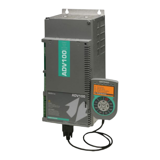
Page 47: Use Of The Keypad
8. Use of the keypad This chapter describes the optional KB-ADV100 keypad and methods of use for displaying and programming inverter parameters. 8.1 Description → Drive status indicator LEDs ← 5-line x 21 character alphanumerical LCD display → Membrane keypad The programming keypad is used to display the status and diagnostics parameters during operation. -
Page 48: Meaning Of Leds
8.1.2 Meaning of LEDs LEDs Colore Significato dei Led Yellow The LED is lit, when the drive operates with a positive torque Yellow The LED is lit, when the drive operates with a negative torque Green The LED is lit during IGBT modulation (drive operating) ILIM When this LED is lit the drive has reached a current limit condition. -
Page 49: Scanning Of The Parameters
• ENUM type parameter: displays the numeric value corresponding to the current selection. • Command: in the case of an error in the command, indicates that ESC must be pressed to terminate the com- mand. • Messages and error conditions: Param read only attempt to modify a read-only parameter Password active... -
Page 50: How To Save Parameters
● Binary parameters (BIT type) The parameter may assume only two states which are indicated as On-Off or 0-1. 13 DIGITAL OUTPUTS 13 DIGITAL OUTPUTS 13 DIGITAL OUTPUTS 13 DIGITAL OUTPUTS 14 ANALOG INPUTS 05/8 PAR: 1430 05/8 PAR: 1430 05/8 PAR: 1430 ... -
Page 51: Configuration Of The Display
8.5 Configuration of the display 6.5.1 Language selection Menu 04 DRIVE CONFIG, parameter 04.14 Language select, PAR: 578, default=English. This is used to set one of the languages available: English, Italian, French, German, Spanish, Polish, Romanian, Russian (*), Turkish and Portuguese. 01 MONITOR 04 DRIVE CONFIG 04 DRIVE CONFIG... -
Page 52: Alarm Reset
8.6.1 Alarm reset • If the alarm page is displayed: Pressing the RST key, the alarms are reset and all alarms that have been reset are eliminated from the list. If, after this operation, the list of alarms is empty, the alarm page is closed. If the list is not empty, press the ► key to exit the alarms page. -
Page 53: Saving Of Parameters On The Keypad
8.8.2 Saving of parameters on the keypad 01 MONITOR 04 DRIVE CONFIG 02 DRIVE INFO 16/20 PAR: Drive - - > K2006- 1 03 STARTUP WIZARD Save par to keypad Press E to execute 04 DRIVE CONFIG 05 REFERENCES Menu 04 DRIVE CONFIG, parameter 04.16 Save par to keypad, PAR: 590. -
Page 54: Saving And Recovery Of New Parameter Settings On Memory Card
8.9 Saving and recovery of new parameter settings on memory card To save drive parameters on the memory card (SD-Secure Digital): Menu 04 DRIVE CONFIG, parameter 04.19 Save to SD card, PAR: 01 MONITOR 04 DRIVE CONFIG Salva par-> card SD Salva par->... -
Page 55: Commissioning Via Keypad
9 - Commissioning via keypad Adjustable frequency drives are electrical apparatus for use in industrial installations. Parts of the Drives are energized during operation. The electrical installation and the opening of the device should therefore only be carried out by qualified personnel. Improper installation of motors or Drives may therefore cause the failure of the device as well as serious injury to persons or material Warning! damage. - Page 56 Ne pas utiliser cet appareil en tant que « dispositif d’arrêt d’urgence » (cf. EN 60204, 9.2.5.4). Never open the device or covers while the AC Input power supplyis switched on. Minimum time to wait before working on the terminals or inside the device is listed in section 4.6.
-
Page 57: Asynchronous Motor Startup Wizard
9.1 Asynchronous motor startup wizard The ADV100 can operate with regulation modes: Voltage/Frequency (SSC) , Sensorless (open loop) and field-oriented vector control (closed loop). Note! Before starting, check the factory settings: Menu 02 DRIVE INFO, parameter 02.1 Drive series, PAR: 482, default=7. 01 MONITOR 02 DRIVE INFO 02 DRIVE INFO... - Page 58 Step 1 - Electrical connections Make the connections as described in paragraph 7.4.2. Checks to be performed before powering the drive • Check that the supply voltage is correct and that the input terminals on the drive (L1, L2 and L3) are connected correctly.
- Page 59 Rated speed [rpm]: rated speed of the motor; this value must reflect the speed of the fully loaded motor at rated frequency. If slip is indicated on the motor data plate, set the Rated speed parameter as follows: Rated speed = Synchronous speed - Slip (e.g. for a 4-pole motor Rated speed = 1500 - 70 = 1430).
- Page 60 Step 3B - Self-tuning with motor at stand-still or coupled to the load (Autotune still) Use this procedure when the motor is coupled to the transmission and cannot rotate freely. May cause limited rotation of the shaft. Peut entraîner une rotation de l’arbre limitée. Caution Note ! Autotuning can be cancelled at any time by pressing...
- Page 61 STARTUP WIZARD ▲ 10.01 s SEQ. 01 PAR: 700 SEQ. 02 PAR: Set ramps ? Acceleration time 0 Deceleration time 0 ▼ 10.00 s 10.00 s 9.99 s E=Yes Down=Next Def: 10.00 Def: 10.00 STARTUP WIZARD Set application par? E=Yes Down=Next Note !
- Page 62 Step 7 - Speed tests In this step the basic settings in order to perform a functional test of the drive-motor system are described. This functional test uses factory settings as far as the analog and digital commands of the drive are concerned. The preset regulation mode is V/f.
-
Page 63: First Customized Start-Up
16.6 2010 Rated power Motor rated power 16.9 2022 Autotune rotation Self-tuning with motor rotating 16.10 2024 Autotune still Self-tuning with motor at stand-still or coupled to the load 5.24 Full scale speed Maximum speed setting Acceleration time 0 Acceleration time 0 Deceleration time 0 Deceleration time 0 Save parameters... - Page 64 • Setting the type of analog reference If the analog input has been selected, choose the type of signal to use in the Analog inp 1X type parameter (14 - ANALOG INPUTS menu, PAR.1602): ± 10V 0-10V In addition to programming the Analog inp 1X type (PAR.1602) the position of switches S5-S4-S3 on the I/O card must also be checked.
- Page 65 • Input and Output terminals The default setting of the input terminals is as follows: - Terminal 9 Digital input E Enable - Terminal 8 Digital input 1 FR forward src, PAR 1042 - Terminal 7 Digital input 2 FR reverse src, PAR 1044 - Terminal 6 Digital input 3 Multi ref sel 0 src...
-
Page 66: Troubleshooting
10 - Troubleshooting 10.1 Alarms Note ! To reset alarms, see paragraph 8.6.1. In the following table, the Code is visible only from serial line Code Error message shown Sub-code Description on the display No alarm Condition: No alarm present Condition: DC link overvoltage alarm due to energy recovered from the motor. - Page 67 Code Error message shown Sub-code Description on the display Condition: Drive overload alarm. Drive overload The overload threshold of the accumulator of the I²t drive thermal image has been exceeded. Solution: Check that the size of the drive is suitable for the application. Condition: Motor overload alarm.
- Page 68 0001H-1 Incorrect PLC key. PLC application not available. Solution: Contact Gefran to request the key to enable the desired firmware function. Encoder error Condition: this condition may occur when the drive is powered during encoder setup each time parameter 552 Regulation mode is set.
-
Page 69: Speed Fbk Loss Alarm According To The Type Of Feedback
Solution: Contact Gefran in order to update the firmware on the optional encoder card. Condition: an optional card has been removed with respect to the configuration present when the last Save parameters command was executed or No opt card there is a fault on the optional card or on the regulation card. -
Page 70: Messages
10.3 Messages Note ! For more information see chapter 8.7. Index Error message shown Sub-code Description on the display Condition: may occur during loading of the parameter database saved in flash normally appears in the following conditions: at initial power-on when a new firmware version is downloaded, when the regulation is installed on a new size, Load default param when the region is changed. - Page 71 Incorrect PLC key. PLC application not available. Solution: Ask Gefran to supply the correct key to enable the desired firmware function. Condition: this may occur at drive power-on if the incorrect enabling key was inserted for a given firmware function. At this stage the firmware function can Key expiring still be used freely, but this time limit is about to expire.
- Page 72 Solution: Contact Gefran in order to update the firmware on the optional encoder card. Condition: this may occur when powering the drive if an expansion card has been removed or replaced or the incorrect enable key is inserted for a given Options cfg changed firmware function.
-
Page 73: Parameters List
11 - Parameters list 11.1 Legend Menu Description Type Type FB 22 - FUNCTIONS (Level 1 menu) 22.1 - FUNCTIONS/INERTIA COMP (Level 2 menu) 22.1.1 3100 Inertia comp kgm2 FLOAT 100.0 ERWS... -
Page 74: Parameters List (Easy - Expert)
11.2 Parameters list (Easy - Expert) Menu Description Type Type FB 1 - MONITOR Output current FLOAT 16/32BIT Output voltage FLOAT 16/32BIT Output frequency FLOAT 16/32BIT Ramp setpoint INT16 16/32BIT Speed setpoint INT16 16/32BIT Motor speed INT16 16/32BIT DC link voltage FLOAT 16/32BIT Heatsink temperature... - Page 75 Menu Description Type Type FB Enc 2 Enc 3 Enc 4 1032 Enc 5 Can/Dnet Unknown 2.20 Slot3 card type ENUM None None I/O 1 1281 I/O 2 2305 I/O 3 3841 I/O 4 4865 I/O 5 5377 I/O 6 Enc 1 Enc 2 Enc 3...
- Page 76 Menu Description Type Type FB 4.13 Display backlight 4.14 Language select ENUM English English Italian French German Spanish Polish Romanian Russian Turkish Portuguese 4.15 Load default 4.16 Save par to keypad 4.17 Load par from keypad 4.18 Keypad memory select UINT16 4.19 Save to SD card...
- Page 77 Menu Description Type Type FB 6.18 Decel jerk time 2 FLOAT 0.02 10.0 6.19 Accel jerk time 3 FLOAT 0.02 10.0 6.20 Decel jerk time 3 FLOAT 0.02 10.0 6.21 Ramp in zero src LINK 16BIT 6000 16384 L�DIGSEL2 6.22 Ramp out zero src LINK 16BIT...
- Page 78 Menu Description Type Type FB Ramp&Follow Fine&Last val Fine&Follow 8.13 Monitor uscita Mpot INT16 16/32BIT 9 - JOG FUNCTION Jog setpoint INT16 CALCI CALCI Jog acceleration FLOAT 0.01 1000.0 Jog deceleration FLOAT 0.01 1000.0 Jog cmd + src LINK 16BIT 6000 16384 L�DIGSEL2...
- Page 79 Menu Description Type Type FB L�DIGSEL2 11.20 1048 FR start mon 16BIT 11.21 1050 FR reverse mon 16BIT 11.22 1052 FR cmd mon UINT16 12 - DIGITAL INPUTS 12.1 1240 Dig inp 1X inversion 12.2 1242 Dig inp 2X inversion 12.3 1244 Dig inp 3X inversion...
- Page 80 Menu Description Type Type FB L�DIGSEL2 14.29 1678 An inp 2X altsel src LINK 16BIT 6000 16384 L�DIGSEL2 14.30 1682 Analog input 2X dest ILINK 15 - ANALOG OUTPUTS 15.1 1850 Analog out 1X src LINK 16/32BIT 6000 16384 L�ANOUT 15.2 1852 Analog out 2X src...
- Page 81 Menu Description Type Type FB 17.6 2110 Encoder1signal check ENUM Contr A-B ERWZ Check disabled Check A-B Check A-B-Z Check A-B-SE 17.7 2112 Encoder 1 SSI bits UINT16 ERWZ 17.8 2130 Encoder 1 direction ENUM Not inverted Not inverted Inverted 17.9 2132 Encoder 1 mode...
- Page 82 Menu Description Type Type FB LimCop pos/neg 20.4 2358 Torque lim sym/p src LINK 16/32BIT 6000 16384 ERWZ F�S L�LIM 20.5 2370 Torque lim neg src LINK 16/32BIT 6000 16384 ERWZ F�S L�LIM 20.6 2360 Torque lim Pos Inuse FLOAT 16/32BIT 20.7 2362...
- Page 83 Menu Description Type Type FB 22.4 - FUNCTIONS/BRES OVERLOAD 22.4.1 3250 Bres control ERWZ 22.4.2 3252 Bres value FLOAT SIZE 1000.0 ERWS 22.4.3 3254 Bres cont power FLOAT SIZE 100.0 ERWS 22.4.4 3256 Bres overload factor FLOAT SIZE 10.0 ERWS 22.4.5 3258 Bres overload time...
- Page 84 Menu Description Type Type FB 23.1.1 3800 Drive address UINT16 23.1.2 3802 Serial baudrate ENUM 38400 9600 19200 38400 23.1.3 3810 Serial parameter ENUM None,8,1 None,8,1 None,8,2 Even,8,1 Odd,8,1 23.1.4 3804 Serial protocol ENUM Modbus Modbus Jbus 23.1.5 3806 Serial delay UINT16 1000 23.1.6...
- Page 85 Menu Description Type Type FB Eu float Par16 Par32 23.3.7 4034 Fieldbus M->S2 mon INT32 32 BIT 23.3.8 4036 Fieldbus M->S2 div float 1000.0 23.3.9 4040 Fieldbus M->S3 ipa FBM2SIPA 20000 23.3.10 4042 Fieldbus M->S3 sys ENUM Not assigned Not assigned Count16 Count32 Fill16...
- Page 86 Menu Description Type Type FB Eu float Par16 Par32 23.3.27 4084 Fieldbus M->S7 mon INT32 32 BIT 23.3.28 4086 Fieldbus M->S7 div float 1000.0 23.3.29 4090 Fieldbus M->S8 ipa FBM2SIPA 20000 23.3.30 4092 Fieldbus M->S8 sys ENUM Not assigned Not assigned Count16 Count32 Fill16...
- Page 87 Menu Description Type Type FB Par16 Par32 23.3.47 4134 Fieldbus M->S12 mon INT32 32 BIT 23.3.48 4136 Fieldbus M->S12 div float 1000.0 23.3.49 4140 Fieldbus M->S13 ipa FBM2SIPA 20000 23.3.50 4142 Fieldbus M->S13 sys ENUM Not assigned Not assigned Count16 Count32 Fill16 Fill32...
- Page 88 Menu Description Type Type FB Eu float Par16 Par32 23.4.3 4184 Dig Fieldbus S->M1 INT3232 BIT 23.4.4 4186 Fieldbus S->M1 mul float 1000.0 23.4.5 4190 Fieldbus S->M2 ipa FBS2MIPA 20000 23.4.6 4192 Fieldbus S->M2 sys ENUM Not assigned Not assigned Count16 Count32 Fill16...
- Page 89 Menu Description Type Type FB Par16 Par32 23.4.23 4234 Dig Fieldbus S->M6 INT32 32 BIT 23.4.24 4236 Fieldbus S->M6 mul float 1000.0 23.4.25 4240 Fieldbus S->M7 ipa FBS2MIPA 20000 23.4.26 4242 Fieldbus S->M7 sys ENUM Not assigned Not assigned Count16 Count32 Fill16 Fill32...
- Page 90 Menu Description Type Type FB Par32 23.4.43 4284 Dig Fieldbus S->M11 INT32 32 BIT 23.4.44 4286 Fieldbus S->M11 mul float 1000.0 23.4.45 4290 Fieldbus S->M12 ipa FBS2MIPA 20000 23.4.46 4292 Fieldbus S->M12 sys ENUM Not assigned Not assigned Count16 Count32 Fill16 Fill32 Mdplc16...
- Page 91 Menu Description Type Type FB 23.4.63 4334 Dig Fieldbus S->M16 INT32 32 BIT 23.4.64 4336 Fieldbus S->M16 mul float 1000.0 23.5 - COMMUNICATION/WORD COMP 23.5.1 4400 Word bit0 src LINK 16 BIT 6000 16384 L�DIGSEL1 23.5.2 4402 Word bit1 src LINK 16 BIT 6000...
- Page 92 Menu Description Type Type FB 24.7 4520 MotorOT src LINK 16 BIT 6000 16384 L�DIGSEL2 24.8 4522 MotorOT activity ENUM Warning Ignore Warning Disable Stop Fast stop 24.9 4524 MotorOT restart ENUM Disable Disable Enable 24.10 4526 MotorOT restart time UINT16 1000 30000...
- Page 93 Menu Description Type Type FB Enable 24.33 4622 IOverC restart time UINT16 2000 1000 10000 24.34 4630 OverV restart ENUM Disable Disable Enable 24.35 4632 OverV restart time UINT16 2000 1000 10000 24.36 4640 UnderV restart ENUM Enable Disable Enable 24.37 4642 UnderV restart time...
- Page 94 Menu Description Type Type FB Overcurrent Desaturation MultiUndervolt MultiOvercurr MultiDesat Heatsink OT HeatsinkS OTUT Intakeair OT Motor OT Drive overload Motor overload Bres overload Phaseloss Opt Bus fault Opt 1 IO fault Opt 2 IO fault Opt Enc fault External fault Speed fbk loss Overspeed Speed ref loss...
- Page 95 Menu Description Type Type FB Plc6 fault Plc7 fault Plc8 fault 24.48 4706 Alarm dig sel 4 ENUM No alarm No alarm Overvoltage Undervoltage Ground fault Overcurrent Desaturation MultiUndervolt MultiOvercurr MultiDesat Heatsink OT HeatsinkS OTUT Intakeair OT Motor OT Drive overload Motor overload Bres overload Phaseloss...
- Page 96 Menu Description Type Type FB 27.3.2 2154 E1 Virtual position UINT32 32 BIT 27.3.3 2156 E1 Revolutions INT32 32 BIT 27.3.4 2168 E1 Abs pulses UINT32 CALCI 27.3.5 2164 E1 Abs position UINT32 32 BIT 27.3.6 2166 E1 Abs revolutions UINT32 32 BIT 27.4 - SERVICE/FIELDBUS SERV...
-
Page 97: Selection Lists
11.3 Selection lists Description Menu Description Menu Description Menu Output frequency Speed thr 1_2 mon 0.0 (*) Torque current ref Set speed 0.0 (*) L_ANOUT Magnet current ref 1.10 Speed thr 3 mon 0.0 (*) 6000 Null 0.0 (*) Torque current 1.11 Current thr mon 0.0 (*) - Page 98 Description Menu Description Menu Description Menu 4464 Bit5 decomp mon 23.6.8 4472 Bit9 decomp mon 23.6.12 4094 Fieldbus M->S8 mon 23.3.31 4466 Bit6 decomp mon 23.6.9 4474 Bit10 decomp mon 23.6.13 4104 Fieldbus M->S9 mon 23.3.35 4468 Bit7 decomp mon 23.6.10 4476 Bit11 decomp mon...
- Page 99 Description Menu Description Menu Description Menu 1600 Analog input 1X mon 14.1 3702 Pad 2 22.7.2 1650 Analog input 2X mon 14.16 3704 Pad 3 22.7.3 4024 Fieldbus M->S1 mon 23.3.3 3706 Pad 4 22.7.4 4034 Fieldbus M->S2 mon 23.3.7 3708 Pad 5 22.7.5...
-
Page 100: Appendix
Appendix A.1 - ADV100 Basic Configuration ADV100 is coded as the BASIC version (see chepter 2.3 Standard configurations) and does not implement any I/O or encoder expansion cards. The user may integrate any of the available options, to meet specific system requirements. These integrations can be performed quickly and simply, by inserting the cards in the relative connectors on the regulation card (provided as standard with the drive and not interchangeable). -
Page 101: I/O Cards
A.2 - I/O Cards ● EXP-IO-D6A4R2-F-ADL (standard) 1 enable input (Enable) + 6 digital inputs (DI) + 2 analog inputs (AI) + 2 analog outputs (AO) + 2 relay outputs (RO). The terminals of this card are not extractable. EXP-IO-D6A4R2-F-ADL ... - Page 102 ● EXP-IO-D8R4-ADL (optional) 1 enable input (Enable) + 8 digital inputs (DI) + 4 relay outputs (RO) EXP-IO-D8R4-ADL 50 51 52 53 54 55 56 57 10 11 12 ● EXP-IO-D8A4R4-ADL (optional) 1 enable input (Enable) + 8 digital inputs (DI) + 2 analog inputs (AI) + 2 analog outputs (AO) + 4 relay outputs (RO) EXP-IO-D8A4R4-ADL ...
- Page 103 ● EXP-IO-D16R4-ADL (optional) 1 enable input (Enable) + 12 digital inputs (DI) + 4 digital outputs (DO) + 4 relay outputs (RO) EXP-IO-D16R4-ADL 50 51 52 53 54 55 56 57 20 21 22 23 24 25 26 27 28 29 10 11 12 ADV100 •...
-
Page 104: Input/Output Features
A.2.1 Input/Output features 24V DC power supply Tolerance ± 10% Maximum current 150 mA Isolation 1 KV ● Digital inputs (DI) and enable hardware inputs (EN-HW) Description Features Type 24 V PNP / NPN Operating voltage 0 V to + 24 V (+ 30 V max) Load 5 mA @ +24 V - R = 4.7 kΩ... - Page 105 Isolation AI-X AI-X AI-X (*) Selezione ingresso V/I (V=OFF, I=ON) ● Analog outputs (AO) Description Features Type Single-ended in voltage Input voltage ± 10 V (± 12.5 V full scale) Load 5 mA @ ± 10 V - R = 2.2 kΩ Resolution 12 Bits (11 + sign) Precision...
-
Page 106: Encoders And Encoder Expansion Cards
A.3 Encoders and encoder expansion cards A.3.1 Encoders Encoders provide motor speed and position feedback The regulation algorithms in the ADV100 drive are capable of controlling asynchronous motors, it may or may not use the speed measurement obtained from the encoder reading. The regulation algorithm needs an encoder that also allows the absolute motor position to be verified. -
Page 107: Encoder Cards
A.3.2 Encoder cards Note ! The encoder power supply must be adequate considering the cable length and the absorption rates as shown in table (1) at the end of this chapter. EXP-DE-I1-ADL (Standard) Digital Incremental Encoder. This is the default card supplied with drives ADV120-...- to control asynchronous motors in field-oriented flux vector mode (FOC). - Page 108 INCREMENTAL DIGITAL ENCODER (DE) SINGLE ENDED NPN O.C. 0VE out +VE out INCREMENTAL DIGITAL ENCODER (DE) SINGLE ENDED PNP O.C. 0VE out +VE out (*) Connection of shielding, see figure 7.2.4 ADV100 • Quick installation guide - Specifications and connection...
- Page 109 EXP-DE-I1R1F2-ADL Digital Incremental Encoder, to control asynchronous motors in field-oriented flux vector mode (FOC). EXP-DE-I1R1F2-ADL 20 21 22 23 10 11 12 13 14 15 (TTL Line-driver) Channels ������������������������������� A+ A-, B+ B-, Z+ Z-, differential line drivers, optoisolated. Management of loss of encoder signals Max frequency ��������������������������...
- Page 110 INCREMENTAL DIGITAL ENCODER (DE) SINGLE ENDED NPN O.C. 0VE out +VE out INCREMENTAL DIGITAL ENCODER (DE) SINGLE ENDED PNP O.C. 0VE out +VE out (*) Connection of shielding, see figure 7.2.4 Internal power supply The internal power supply of the encoder can be selected from the keypad (ENCODER CONFIG menu, parameter Encoder supply (PAR 2102) to balance the loss of voltage due to the length of the encoder cable and load current, minimum step 0.1 V Encoder option type Enc 1...
- Page 112 GEFRAN BENELUX GEFRAN FRANCE GEFRAN SIEI Electric Pte Ltd Lammerdries-Zuid, 14A 4, rue Jean Desparmet - BP 8237 Block B, Gr.Flr, No.155, Fu Te Xi Yi Road, B-2250 OLEN 69355 LYON Cedex 08 Wai Gao Qiao Trade Zone Ph. +32 (0) 14248181 Ph.
Need help?
Do you have a question about the SIEIDrive ADV100 and is the answer not in the manual?
Questions and answers