
Related Manuals for gefran ADV20 series


Summary of Contents for gefran ADV20 series
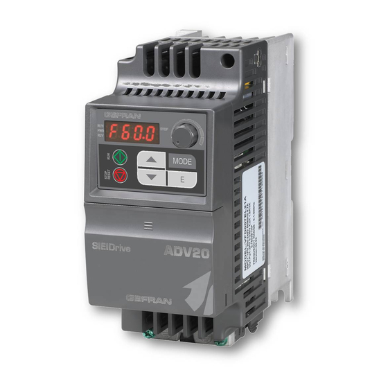
- Page 1 Compact V/f AC Drive 0.4 to 3.7 kW 115-230 Vac 1ph, 230-460 Vac 3ph ADV20 Italiano - English ..Quick Start-up and specification...
- Page 2 Drive & Motion Control Unit V/f control V/f & Sensorless Vector Vector Field Oriented Technology Vettoriale Orientam. di Flusso Controllo Model ADV20 ADV50 ADV200 Modello Specifications - Specifiche 0.5 … 5 Hp 0.5 … 15 Hp 1 … 60 Hp Power 0,4…...
- Page 3 Profibus DP, Profibus DP, CANopen, CANopen, CANopen CANopen FastLink, GDNet Interbus S GEFRAN S.p.A. Drive & Motion Control Unit Headquarters Technical Assistance Via Carducci 24 Via Sebina 74 technohelp@gefran.com 21040 Gerenzano [VA] - ITALY 25050 Provaglio d’Iseo (BS) - ITALY Customer Service Ph.
- Page 4 Drive & Motion Control Unit V/f control V/f & Sensorless Vector Vector Field Oriented Technology Vettoriale Orientam. di Flusso Controllo Model ADV20 ADV50 ADV200 Modello Applications - Applicazioni Centrifugal Pumps & Fans ● ● ● Pompe Centrifughe e Ventilatori Conveyors ●...
- Page 5 Torque Vector Flux Vector Digital DC Servo Vettoriale di coppia Vettoriale di flusso Convertitori Digitali AGy-EV XVy-EV TPD32 Applications - Applicazioni ● ● ● ● ● ● ● ● ● ● ● ● ● ● ● ● ● ● ● ●...
- Page 6 This page intentionally left blank.
- Page 7 Introduzione Grazie per avere scelto la serie multifunzione ADV20 di GEFRAN. La serie ADV20 è realizzata con componenti e materiali di alta qualità integrando le più recenti tecnologie a microprocessori disponibili. Prima di iniziare Queste brevi informazioni saranno utili nell'installazione e nell'impostazione dei parametri dei drive CA.
- Page 8 Specifiche Classe 115 V Classe di tensione Numero modello ADV20-XXXX 1004 2007 Max. potenza motore applicabile (kW) 0,75 Max. potenza motore applicabile (Hp) Potenza nominale in uscita (kVA) Corrente nominale in uscita (A) Massima tensione in uscita (V) 3 fasi proporzionali al doppio della tensione in ingresso Frequenza in uscita (Hz) 0,1~600 Hz Frequenza portante (kHz)
- Page 9 Specifiche generali Controllo V/f con modulazione SPWM (Modulazione ad ampiezza di impulso Sistema di controllo sinusoidale) Risoluzione impostazione di 0,01 Hz frequenza Risoluzione frequenza di uscita 0,01 Hz Compresa funzione auto-torque/auto compensazione di slittamento; la coppia di Caratteristiche di coppia spunto può...
- Page 10 Schema di base del cablaggio Gli utenti devono effettuare i collegamenti attenendosi allo schema del circuito sottostante. Figura 1 per i modelli ADV20-…-…-1M/2M Resistore di frenatura (opzionale) Unità di frenatura (opzionale) usibile Interruttore senza fusibile) /NFB ( Motore R(L1) R(L1) U(T1) S(L2) S(L2)
- Page 11 Figura 2 per i modelli ADV20-…-…-4 Resistore di frenatura (opzionale) Unità di frenatura (opzionale) usibile Interruttore senza fusibile) /NFB ( Motore R(L1) R(L1) U(T1) S(L2) S(L2) V(T2) T(L3) T(L3) W(T3) Circuito raccomandato quando l'alimentazione Contatti di Uscita multifunzione viene scollegata per 240Vac 2.5A Max.
- Page 12 C. Modalità PNP senza alimentazione D. Modalità PNP con alimentazione esterna esterna +24V +24V FWD/Stop FWD/Stop REV/Stop REV/Stop Multi-step 1 Multi-step 1 Impostazione Impostazione di fabbrica di fabbrica Multi-step 2 Multi-step 2 Multi-step 3 Multi-step 3 Multi-step 4 Multi-step 4 V dc Morsetti di alimentazione e morsetti di controllo Dimensione A...
- Page 13 Descrizione dei morsetti Simbolo morsetto Descrizione della funzione del morsetto R/L1, S/L2, T/L3 Morsetti di ingresso linea CA (monofase/trifase) Morsetti di uscita drive CA per il collegamento del motore trifase a U/T1, V/T2, W/T3 induzione Collegamenti per l’unità di frenatura esterna (serie BU-2/4- +, - ADV20/50) Collegamento a terra, nel rispetto delle normative locali.
- Page 14 Simbolo Impostazioni di fabbrica (modalità NPN) Funzione del morsetto morsetto ON: Collegamento al DCM Comune per ingressi digitali e utilizzato per la Comune segnale digitale modalità NPN. Uscita a relè multifunzione Carico resistivo: (N.O.) a 5 A (N.O.)/3 A (N.C.) 240 VCA 5 A (N.O.)/3 A (N.C.) 24 VCC Carico induttivo: Uscita a relè...
- Page 15 Descrizione del tastierino digitale STOP MODE Visualizzazione stato Tasti SU e GIÙ Visualizza lo stato attuale del drive. Imposta il numero di parametro e cambia i dati numerici, come la frequenza master. Visualizzazione LED MODE Indica frequenza, tensione, corrente, unità Cambia tra varie modalità...
- Page 16 Sintesi delle impostazioni dei parametri : Il parametro può essere impostato durante il funzionamento. Impostazioni Parametro Descrizione Impostazioni NOTA di fabbrica Gruppo 0: Parametri utente 00.00 Codice di Sola lettura identificazione del drive CA 00.01 Visualizzazione della Sola lettura corrente nominale del drive CA 0: Il parametro può...
- Page 17 Impostazioni Parametro Descrizione Impostazioni NOTA di fabbrica Valore 1 definito 0 a 9999 dall’utente 00.13 00.13 (corrisponde alla frequenza max.) Posizione del Punto 0 a 3 00.14 Decimale del Valore 1 definito dall’utente Gruppo 1: Parametri di base Massima frequenza in 01.00 da 50,00 a 600,0 Hz 60.00...
- Page 18 Impostazioni Parametro Descrizione Impostazioni NOTA di fabbrica Gruppo 2: Parametri metodo di funzionamento 0: Tasti SU/GIÙ del tastierino digitale o ingressi multifunzione SU/GIÙ. Memorizzazione dell'ultima frequenza utilizzata. Sorgente del 02.00 1: da 0 a +10 V da AVI comando principale 2: da 4 a 20 mA da ACI frequenza master 3: Comunicazione RS-485 (RJ-45)
- Page 19 Impostazioni Parametro Descrizione Impostazioni NOTA di fabbrica 0: Tasti SU/GIÙ del tastierino digitale o ingressi multifunzione SU/GIÙ. Memorizzazione dell'ultima frequenza utilizzata. Sorgente del 1: da 0 a +10 V da AVI 02.09 comando della 2: da 4 a 20 mA da ACI seconda frequenza 3: Comunicazione RS-485 (RJ-45) 4: Potenziometro tastierino digitale...
- Page 20 Impostazioni Parametro Descrizione Impostazioni NOTA di fabbrica Gruppo 3: Parametri funzioni di uscita 0: Nessuna funzione 1: Drive CA operativo 2: Frequenza master raggiunta 3: Velocità zero 4: Rilevamento sovraccoppia 5: Indicazione blocco basi (B.B.) 6: Indicazione bassa tensione 7: Indicazione modalità di funzionamento 8: Indicazione guasto 9: Frequenza desiderata raggiunta 10: Valore conteggio morsetto raggiunto...
- Page 21 Impostazioni Parametro Descrizione Impostazioni NOTA di fabbrica Visualizza lo stato 03.13 Sola lettura del relè Gruppo 4: Parametri funzioni di ingresso Regolazione bias 04.00 potenziometro del da 0,0 a 100,0 % tastierino Polarità bias 0: Bias positivo 04.01 1: Bias negativo potenziometro del tastierino Guadagno...
- Page 22 Impostazioni Parametro Descrizione Impostazioni NOTA di fabbrica Tempo antirimbalzo in 04.10 ingresso del morsetto da 1 a 20 (*2ms) digitale 04.11 Tensione minima AVI da 0,0 a 10,0 V Frequenza minima da 0,0 a 100,0% 04.12 Tensione massima 04.13 da 0,0 a 10,0 V 10.0 Frequenza massima 04.14...
- Page 23 Impostazioni Parametro Descrizione Impostazioni NOTA di fabbrica 05.12 Frequenza 13ª da 0,00 a 600,0 Hz 0.00 velocità 05.13 Frequenza 14ª da 0,00 a 600,0 Hz 0.00 velocità 05.14 Frequenza 15ª da 0,00 a 600,0 Hz 0.00 velocità Gruppo 6: Parametri di protezione Serie 115 V/230 V: da 330,0 V a 410,0 V 390,0 V Prevenzione di stallo...
- Page 24 Impostazioni Parametro Descrizione Impostazioni NOTA di fabbrica 13: Riservato 14: Perdita di fase (PHL) 15: Riservato celerazione (CFA) 16: Errore autoaccelerazione/de 17: Protezione password/SW (codE) 18: Errore di SCRITTURA CPU scheda di alimentazione (cF1.0) 19: Errore di LETTURA CPU scheda di alimentazione (cF2.0) Registrazione 06.10...
- Page 25 Livello di allarme 07.15 0,1~10,0 V surriscaldamento PTC del motore Livello di reimpostazione 07.16 Gefran per 0,1~5,0 V surriscaldamento PTC del motore Trattamento del 0: Avvisa e si arresta con RAMPA 07.17 surriscaldamento 1: Avvisa e si arresta per INERZIA...
- Page 26 Impostazioni Parametro Descrizione Impostazioni NOTA di fabbrica Tempo di ripristino da 0,1 a 6000 sec 08.16 automatico al riavvio 60.0 dopo guasto Risparmio 0: Disattiva 08.17 automatico di 1: Attiva energia 0: Attiva funzione AVR 1: Disattiva funzione AVR 08.18 Funzione AVR 2: Disattiva funzione AVR in fase di decelerazione.
- Page 27 Impostazioni Parametro Descrizione Impostazioni NOTA di fabbrica 0: Retroazione PID positivo da morsetto esterno AVI (0 ~ +10 VCC) 1: Retroazione PID negativo da morsetto Terminale di esterno AVI (0 ~ +10 VCC) 10.01 ingresso per 2: Retroazione PID positivo da morsetto retroazione PID esterno ACI (4 ~ 20 mA) 3: Retroazione PID negativo da morsetto...
- Page 28 Impostazioni Parametro Descrizione Impostazioni NOTA di fabbrica Tempo ritardo riavvio 10.21 dopo livello errato di 1 a 9999 sec deviazione PID Impostazione livello 10.22 0 a 100% deviazione Tempo rilevazione 10.23 dell'impostazione 0 a 9999 sec livello deviazione Livello Offset della 10.24 0 a 50% dispersione liquido...
- Page 29 Sovraccarico 2 Sovraccarico del motore. sovraccoppia a un valore appropriato (da Pr.06.03 a Pr.06.05). CC (morsetto corrente) Contattare l’Assistenza Tecnica di Gefran. Errore hardware OV Errore hardware GFF Contattare l’Assistenza Tecnica di Gefran. Errore hardware OC Quando il morsetto di ingresso esterno (B.B.) è...
- Page 30 La potenza di uscita del drive CA è troppo bassa: Sostituire il drive CA con un modello di potenza immediatamente superiore. Impossibile programmare il circuito Contattare l’Assistenza Tecnica di Gefran. integrato EEPROM. Impossibile programmare il circuito Contattare l’Assistenza Tecnica di Gefran.
- Page 31 Utilizzare il calcolo corretto del checksum Per informazioni dettagliate vedere il gruppo 9 al capitolo 5 (Manuale Utente ADV20, sul cd-rom).. Contattare l’Assistenza Tecnica di Gefran. Errore di protezione software Controllare il cablaggio ACI Errore di segnale analogico...
- Page 32 Questa pagina lasciata Intenzionalmente bianca ADV20 QS, V1.02 Italiano English...
- Page 33 ADV20 series is used only to control variable speed of 3-phase induction motors, NOT for 1-phase motors or other purpose. ADV20 series shall NOT be used NOT for those devices that may cause personal injury, such as life support equipment or any life safety situation.
- Page 34 Specifications Voltage Class 115V Class Model Number ADV20-XXXX 1004 2007 Max. Applicable Motor Output (kW) 0.75 Max. Applicable Motor Output (hp) Rated Output Capacity (kVA) Rated Output Current (A) Maximum Output Voltage (V) 3-Phase Proportional to Twice the Input Voltage Output Frequency (Hz) 0.1~600 Hz Carrier Frequency (kHz)
- Page 35 General Specifications Control System SPWM(Sinusoidal Pulse Width Modulation) control (V/f control) Frequency Setting Resolution 0.01Hz Output Frequency Resolution 0.01Hz Including the auto-torque/auto-slip compensation; starting torque can be Torque Characteristics 150% at 5.0Hz Overload Endurance 150% of rated current for 1 minute Skip Frequency Three zones, setting range 0.1-600Hz Accel/Decel Time...
- Page 36 Basic Wiring Diagram Users must connect wiring according to the following circuit diagram shown below. Figure 1 for models of ADV20-…-…-1M/2M Series braking resistor (optional) braking unit (optional) None Fuse Breaker) Fu se/NF B( Motor R(L1) R(L1) U(T1) S(L2) S(L2) V(T2) W(T3) Recommended Circuit...
- Page 37 Figure 2 for models of ADV20-…-…-4 Series braking resistor (optional) braking unit (optional) None Fuse Breaker) Fu se/NF B( Motor R(L1) R(L1) U(T1) S(L2) S(L2) V(T2) T(L3) T(L3) W(T3) Recommended Circuit when power supply Multi-function contact output is turned OFF by a 240Vac 2.5A Max.
- Page 38 C. PNP mode without external power D. PNP mode with external power +24V +24V FWD/Stop FWD/Stop REV/Stop REV/Stop Multi-step 1 Multi-step 1 Factory Factory Multi-step 2 Multi-step 2 setting setting Multi-step 3 Multi-step 3 Multi-step 4 Multi-step 4 Power Terminals and Control Terminals Frame A Frame B Frame...
- Page 39 Terminal Explanations Terminal Symbol Explanation of Terminal Function R/L1, S/L2, T/L3 AC line input terminals (1-phase/3-phase) U/T1, V/T2, W/T3 AC drive output terminals for connecting 3-phase induction motor +, - Connections for External Brake unit (BU-2/4-ADV20/50 series) Earth connection, please comply with local regulations. The specification for the control terminals The position of the control terminals MI1 MI3 MI5...
- Page 40 Terminal Factory Settings (NPN mode) Terminal Function Symbol ON: Connect to DCM +24V DC Voltage Source +24VDC, 50mA used for PNP mode. Common for digital inputs and used for NPN Digital Signal Common mode. Multi-function Relay output Resistive Load: (N.O.) a 5A(N.O.)/3A(N.C.) 240VAC 5A(N.O.)/3A(N.C.) 24VDC Multi-function Relay output...
- Page 41 Description of the Digital keypad STOP MODE Status Display UP and DOWN Key Display the driver’s current status Set the parameter number and changes the numerical data, such as Master Frequency. LED Display MODE Indicates frequency, voltage, current, user defined Change between different display mode.
- Page 42 Summary of Parameter Settings : The parameter can be set during operation. Factory Parameter Explanation Settings NOTE Setting Group 0 User Parameters 00.00 Identity Code of the Read-only AC motor drive 00.01 Rated Current Read-only Display of the AC motor drive 0: Parameter can be read/written 1: All parameters are read only 8: Keypad lock...
- Page 43 Factory Parameter Explanation Settings NOTE Setting Position of Decimal 0 to 3 00.14 Point of User- defined Value 1 Group 1 Basic Parameters Maximum Output 01.00 50.00 to 600.0 Hz 60.00 Frequency (Fmax) Maximum Voltage 01.01 0.10 to 600.0 Hz 60.00 Frequency (Fbase) Maximum Output...
- Page 44 Factory Parameter Explanation Settings NOTE Setting 0: Digital keypad 1: External terminals. Keypad STOP/RESET enabled. 2: External terminals. Keypad STOP/RESET Source of First disabled. 02.01 Operation 3: RS-485 (RJ-45) communication. Keypad Command STOP/RESET enabled. 4: RS-485 (RJ-45) communication. Keypad STOP/RESET disabled. 0: STOP: ramp to stop;...
- Page 45 Factory Parameter Explanation Settings NOTE Setting 0: First Master Frequency Command Combination of the 1: First Master Frequency Command+ First and Second 02.10 Second Master Frequency Command Master Frequency 2: First Master Frequency Command - Command Second Master Frequency Command Keypad Frequency 0.00 to 600.0Hz 02.11...
- Page 46 Factory Parameter Explanation Settings NOTE Setting Group 3 Output Function Parameters 0: No function 1: AC drive operational 2: Master frequency attained 3: Zero speed 4: Over torque detection 5: Base-Block (B.B.) indication 6: Low-voltage indication 7: Operation mode indication 8: Fault indication 9: Desired frequency attained 10: Terminal count value attained...
- Page 47 Factory Parameter Explanation Settings NOTE Setting Display the Status of 03.13 Read only Relay Group 4 Input Function Parameters Keypad 04.00 0.0 to 100.0 % Potentiometer Bias Keypad 0: Positive bias 04.01 Potentiometer Bias 1: Negative bias Polarity Keypad 04.02 0.1 to 200.0 % 100.0 Potentiometer Gain...
- Page 48 Factory Parameter Explanation Settings NOTE Setting Digital Terminal 04.10 Input Debouncing 1 to 20 (*2ms) Time 04.11 Min AVI Voltage 0.0 to 10.0V 04.12 Min AVI Frequency 0.0 to 100.0% 04.13 Max AVI Voltage 0.0 to 10.0V 10.0 04.14 Max AVI Frequency 0.0 to 100.0% 100.0 04.15...
- Page 49 Factory Parameter Explanation Settings NOTE Setting 05.12 13th Step Speed 0.00 to 600.0 Hz 0.00 Frequency 05.13 14th Step Speed 0.00 to 600.0 Hz 0.00 Frequency 05.14 15th Step Speed 0.00 to 600.0 Hz 0.00 Frequency Group 6 Protection Parameters 390.0V 115/230V series: 330.0V to 410.0V Over-Voltage Stall...
- Page 50 Factory Parameter Explanation Settings NOTE Setting during steady state operation (ocn) 12: Ground fault (GFF) 13: Reserved 14: Phase-Loss (PHL) 15: Reserved 16: Auto Acel/Decel failure (CFA) 17: SW/Password protection (codE) 18: Power Board CPU WRITE failure (cF1.0) Third Most Recent 06.10 19: Power Board CPU READ failure (cF2.0) Fault Record...
- Page 51 Factory Parameter Explanation Settings NOTE Setting Motor PTC 07.15 Overheat Warning 0.1~10.0V Level Motor PTC 07.16 Overheat Reset 0.1~5.0V Delta Level Treatment of the 0: Warn and RAMP to stop 07.17 Motor PTC 1: Warn and COAST to stop Overheat 2: Warn and keep running Group 8 Special Parameters DC Braking Current...
- Page 52 Factory Parameter Explanation Settings NOTE Setting 0: Disable 08.17 Auto Energy Saving 1: Enable 0: AVR function enable 1: AVR function disable 08.18 AVR Function 2: AVR function disable for decel. 3: AVR function disable for stop 08.19 Reserved Compensation 0.0~5.0 08.20 Coefficient for Motor...
- Page 53 Factory Parameter Explanation Settings NOTE Setting 0: Positive PID feedback from external terminal AVI (0 ~ +10VDC) 1: Negative PID feedback from external Input Terminal for terminal AVI (0 ~ +10VDC) 10.01 PID Feedback 2: Positive PID feedback from external terminal ACI (4 ~ 20mA) 3: Negative PID feedback from external terminal ACI (4 ~ 20mA)
- Page 54 Factory Parameter Explanation Settings NOTE Setting Set Point Deviation 10.22 0 to 100% Level Detection Time of 10.23 Set Point Deviation 0 to 9999 sec Level Offset Level of 10.24 0 to 50% Liquid Leakage Liquid Leakage 10.25 0 to 100% (0: disable) Change Detection Time Setting for 10.26...
- Page 55 Overload 2 Adjust the over-torque detection setting to an Motor overload. appropriate setting (Pr.06.03 to Pr.06.05). CC (current clamp) Please contact the Gefran Technical Assistance. OV hardware error GFF hardware error Please contact the Gefran Technical Assistance. OC hardware error When the external input terminal (B.B) is...
- Page 56 AC motor drive output power is too small: Replace the AC motor drive with the next higher power model. Internal EEPROM can not be Please contact the Gefran Technical Assistance. programmed. Internal EEPROM can not be Please contact the Gefran Technical Assistance.
- Page 57 Use the correct checksum calculation. Please refer to group 9 in the chapter 5 for detail information (ADV20 User manual on CD). Please contact the Gefran Technical Assistance. Software protection failure Check the wiring of ACI Analog signal error...
- Page 58 This page intentionally left blank. ADV20 QS, V1.02 Italiano English...
- Page 60 Fax +55 (0) 1155851425 info@sieiareg.de Ph. +86 21 5866 7816 gefran@gefran.com.br Ph. +86 21 5866 1555 GEFRAN INC GEFRAN SIEI - UK Ltd. gefransh@online.sh.cn Automation and Sensors GEFRAN DEUTSCHLAND 7 Pearson Road, Central Park 8 Lowell Avenue Philipp-Reis-Straße 9a...
Need help?
Do you have a question about the ADV20 series and is the answer not in the manual?
Questions and answers