Eaton Power Xpert C445 User Manual
Global motor management relay
Hide thumbs
Also See for Power Xpert C445:
- User manual (317 pages) ,
- Safety manual (34 pages) ,
- Installation leaflet (4 pages)
Table of Contents
Advertisement
Quick Links
Advertisement
Table of Contents

Related Manuals for Eaton Power Xpert C445


Summary of Contents for Eaton Power Xpert C445
- Page 1 Power Xpert C445 Global Motor Management Relay User Manual Effective January 2019 Supersedes February 2017 EU: Eaton Industries GmbH Hein-Moeller-Str. 7-11 53115 Bonn, Germany US: Eaton Corporation W126N7250 Flint Drive Menomonee Falls, WI 53051...
- Page 3 OBLIGATION OF EATON. THE CONTENTS OF THIS DOCUMENT SHALL NOT BECOME PART OF OR MODIFY ANY CONTRACT BETWEEN THE PARTIES. In no event will Eaton be responsible to the purchaser or user in contract, in tort (including negligence), strict liability or otherwise for any special, indirect, incidental or consequential...
- Page 4 Power Xpert C445 Global Motor Management Relay Support Services The goal of Eaton is to ensure your greatest possible satisfaction with the operation of our products. We are dedicated to providing fast, friendly, and accurate assistance. That is why we offer you so many ways to get the support you need. Whether it is by phone, fax, or email, you can access Eaton’s support information 24 hours a day, seven days a week.
-
Page 5: Table Of Contents
Pre-Defined Operation Modes ........Power Xpert C445 Global Motor Management Relay MN042003EN—January 2019 www.eaton.com... - Page 6 Ground Fault Monitoring Methods ........Power Xpert C445 Global Motor Management Relay MN042003EN—January 2019 www.eaton.com...
- Page 7 Licenses ............Power Xpert C445 Global Motor Management Relay MN042003EN—January 2019 www.eaton.com...
- Page 8 Figure 45. 120 Vac Input Terminal Diagram ........Power Xpert C445 Global Motor Management Relay MN042003EN—January 2019 www.eaton.com...
- Page 9 Figure 94. C445UM: Monitoring User Interface ....... Figure 95. Isolated 24 Vdc Inputs/24 Vdc Outputs/24 Vdc Power ....Power Xpert C445 Global Motor Management Relay MN042003EN—January 2019 www.eaton.com...
- Page 10 Figure 133. Installing the PROFIBUS Communication Card ..... Figure 134. Base Control Module DIP Switches with PROFIBUS Card ... . . viii Power Xpert C445 Global Motor Management Relay MN042003EN—January 2019 www.eaton.com...
- Page 11 Table 51. High Power ........... Power Xpert C445 Global Motor Management Relay MN042003EN—January 2019 www.eaton.com...
- Page 12 Table 99. Overload Object—Class 0x2C (44) ....... . . Power Xpert C445 Global Motor Management Relay MN042003EN—January 2019 www.eaton.com...
- Page 13 Table 128. C445 Modbus Register Map ........Power Xpert C445 Global Motor Management Relay MN042003EN—January 2019 www.eaton.com...
-
Page 14: Definitions And Symbols
Disconnect time. power before checking controllers performing maintenance. Be sure equipment is properly grounded. Wear safety glasses whenever working on electronic controllers or rotating machinery. Power Xpert C445 Global Motor Management Relay MN042003EN—January 2019 www.eaton.com... -
Page 15: Chapter 1-Power Xpert C445 Overview
Eaton Power Xpert C445 global motor management relay. Keep this operating manual handy and distribute to all users, technicians and maintenance personnel for reference. Power Xpert C445 Global Motor Management Relay MN042003EN—January 2019 www.eaton.com... -
Page 16: Catalog Numbering
Frame Size 90 mm A = 45 mm (0.3–45 A) 090 = 11–90 A B = 55 mm (9–72 A) 136 = 17–136 A C = 90 mm (17–136 A) Power Xpert C445 Global Motor Management Relay MN042003EN—January 2019 www.eaton.com... -
Page 17: Figure 4. User Interface Catalog Numbering
ELC-PT04ANNN = 4 platinum thermocouple (PT-100-Ohm) inputs ELC-EX08NNNR = 8 relay outputs ELC-EX08NNNT = 8 24 Vdc transistor outputs ELC-EX06NNNI = 6 high current relay outputs (6 amp/point) ELC-EX08NNSN = 8 toggle switch inputs Power Xpert C445 Global Motor Management Relay MN042003EN—January 2019 www.eaton.com... -
Page 18: Accessories
User interface wiring harnesses are required to utilize the digital inputs on the Control Family of User Interfaces. Use one wiring harness per user interface to connect to these inputs. Power Xpert C445 Global Motor Management Relay MN042003EN—January 2019 www.eaton.com... -
Page 19: Table 4. Catalog Numbers: C445Xu
Standard USB A Male to Micro USB Male cable C445XS-USBMICRO Standard USB A Male to RJ12 cable C445XS-USBRJ12 Standard USB A Male to Loose Leads cable (for use with Modbus Serial terminals) C445XS-USBLEADS Power Xpert C445 Global Motor Management Relay MN042003EN—January 2019 www.eaton.com... -
Page 20: Modules Overview
Module and the user interface through the cable connection Communication Cards: Optional modules to provide communications. PROFIBUS DVP0 and DVP1 (Shown) ● Ethernet for Modbus/TCP and EtherNet/IP ● Power Xpert C445 Global Motor Management Relay MN042003EN—January 2019 www.eaton.com... -
Page 21: Figure 9. Base Module Features And Connections-Bottom View
Cannot be installed in the field. RJ-12 Terminal: Connection port to the Base Control Module. Pass through current measurement: for measuring motor lead current from 0.3 to 136 A. Power Xpert C445 Global Motor Management Relay MN042003EN—January 2019 www.eaton.com... -
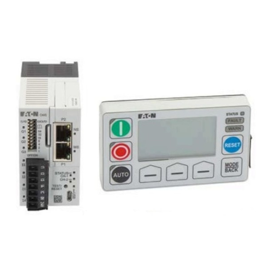
Page 22: Figure 12. C445Um Monitoring User Interface Image
Optional control buttons ● Running, stopped and auto status LEDs ● Fault and warning LEDs ● Micro-USB for connection to PC ● Optional password protection ● Safe remote mounting ● Power Xpert C445 Global Motor Management Relay MN042003EN—January 2019 www.eaton.com... -
Page 23: Chapter 2-Receipt/Unpacking
Inspect the equipment upon delivery. Report any crate or carton damage to the carrier prior to accepting the delivery. Have this information noted on the freight bill. Eaton is not responsible for damage incurred in shipping. Unpacking Remove all packing material from the unit. -
Page 24: Chapter 3-Installation And Wiring
IL043001EN for C44B… Base Control Module IL043003EN for C445M... Measurement Modules IL043002EN for C445UC… Control User Interface IL042004EN for C445UM Monitoring User Interface IL042005EN for C445XG-MOD Ground Fault Module Power Xpert C445 Global Motor Management Relay MN042003EN—January 2019 www.eaton.com... -
Page 25: Clearance
Surrounding air temperature must be less than or equal to 60 °C. A 10 mm clearance between C445 and the enclosure door is recommended. Figure 14. Clearance Dimensions 10 mm ≥ 0.39") ≥ 10 mm ≥ 0.39") ≥ Power Xpert C445 Global Motor Management Relay MN042003EN—January 2019 www.eaton.com... -
Page 26: C445 Module Assembly
(C445XO-RTC) Module and/or Communication Card (C445XC…). If installing only the Memory/RTC module, put the blank cover back in place. If installing a Communication Card, the blank cover can be discarded. Power Xpert C445 Global Motor Management Relay MN042003EN—January 2019 www.eaton.com... -
Page 27: Figure 17. Real-Time Clock And Memory Backup Module Installation
The C445XO-RTC module installation is facilitated by a notch on the upper right corner of the module to provide proper orientation of the module. Firmly push the module into the C445B... pocket until the module is completely seated. Reinstall Option Cover. Power Xpert C445 Global Motor Management Relay MN042003EN—January 2019 www.eaton.com... -
Page 28: Figure 18. Communication Card Installation
Align the modules so there is an offset of 0.098–0.157 in (2.3–4.0 mm). Slide the C445B... Base Module downward on the C445MA... Measurement Module until the locking tab moves into place. Power Xpert C445 Global Motor Management Relay MN042003EN—January 2019 www.eaton.com... -
Page 29: C445 Mounting
All C445 devices may be panel mounted The C445B… base module and C445MA… Measurement Module utilize To aid with the panel layout of the Power Xpert C445 optional mounting feet that are snapped into place. A modules, refer to the dimension drawings. -
Page 30: C445
[1.78] (2) M5 OR #10 [3.97] [1.48] [3.74] [3.15] MTG. 35mm DIN RAIL MOUNT [1.67] [1.34] [.22] MTG. PANEL MOUNT (2) M5 OR #10 [2.72] [2.43] PANEL MOUNT OPTION 2 Power Xpert C445 Global Motor Management Relay MN042003EN—January 2019 www.eaton.com... -
Page 31: Figure 23. Measurement Module-C445Ma
[1.48] 35mm DIN RAIL MOUNT [3.15] [3.15] [1.67] [1.77] [2.90] [1.34] [2.43] [2.72] [3.81] PANEL MOUNT [3.15] [4.31] 2X M5 (SAE #10) PANEL MOUNT PANEL MOUNT OPTION 2 OPTION 1 Power Xpert C445 Global Motor Management Relay MN042003EN—January 2019 www.eaton.com... -
Page 32: Figure 24. Stacked Base Control Module C445B
Figure 24. Stacked Base Control Module C445B… and Measurement Module C445MA… Mounting Dimensions 37.0 [1.46] 80.0 [3.15] 43.0 [1.69] 45.0 156.3 [1.77] [6.15] 167.1 [6.58] PANEL MOUNT (4) M5 OR #10 [3.15] [2.72] [3.74] [2.43] [2.91] PANEL MOUNT OPTION 3 Power Xpert C445 Global Motor Management Relay MN042003EN—January 2019 www.eaton.com... -
Page 33: Figure 25. Measurement Module C445Mb
(2) M5 OR #10 Figure 26. Measurement Module C445MC… Mounting Dimensions [0.31] [3.56] [1.48] 35mm DIN RAIL [3.94] MOUNT [3.31] [4.41] MTG. [1.80] PANEL MOUNT [2.95] MTG. (4) M5 OR #10 Power Xpert C445 Global Motor Management Relay MN042003EN—January 2019 www.eaton.com... -
Page 34: Monitoring User Interface C445Um Mounting Dimensions
Chapter 3—Installation and Wiring Monitoring User Interface C445UM Mounting Dimensions Figure 27. User Interface—Monitoring Option Figure 28. Panel Cutout Options Power Xpert C445 Global Motor Management Relay MN042003EN—January 2019 www.eaton.com... -
Page 35: Figure 29. C445Xg-Mod-C445 External Ground Fault Module
Chapter 3—Installation and Wiring Figure 29. C445XG-MOD—C445 External Ground Fault Module Note: Remove mounting tabs for DIN rail mount. Power Xpert C445 Global Motor Management Relay MN042003EN—January 2019 www.eaton.com... -
Page 36: Figure 30. C445Xg-Ct2-28 Mm Diameter Zero Sequencing Ground Fault Ct
Chapter 3—Installation and Wiring Figure 30. C445XG-CT2—28 mm Diameter Zero Sequencing Ground Fault CT Power Xpert C445 Global Motor Management Relay MN042003EN—January 2019 www.eaton.com... -
Page 37: Figure 31. C445Xg-Ct3-52 Mm Diameter Zero Sequencing Ground Fault Ct
Chapter 3—Installation and Wiring Figure 31. C445XG-CT3—52 mm Diameter Zero Sequencing Ground Fault CT Power Xpert C445 Global Motor Management Relay MN042003EN—January 2019 www.eaton.com... -
Page 38: Figure 32. C445Xg-Ct4-63 Mm Diameter Zero Sequencing Ground Fault Ct
Chapter 3—Installation and Wiring Figure 32. C445XG-CT4—63 mm Diameter Zero Sequencing Ground Fault CT Power Xpert C445 Global Motor Management Relay MN042003EN—January 2019 www.eaton.com... -
Page 39: Figure 33. C445Xg-Ct7-80 X 175 Rectangular Zero Sequencing Ground Fault Ct
Chapter 3—Installation and Wiring Figure 33. C445XG-CT7—80 x 175 Rectangular Zero Sequencing Ground Fault CT Power Xpert C445 Global Motor Management Relay MN042003EN—January 2019 www.eaton.com... -
Page 40: Motor Wiring Connections-Typical
24 0 PE Q1 Q2 Q3 C Q3 I1 I2 I3 I4 C QV 24V C445M... V1 V2 V3 T1 T2 M2, 5 UL-use inch lb-in 1 x 0.2–2.5 1 x 0.2–2.5 1 x 24–12 0.275 0.6 x 3.5 mm PH0, PZ0 0.4–0.5 3.5–4.4 Power Xpert C445 Global Motor Management Relay MN042003EN—January 2019 www.eaton.com... -
Page 41: Motor Connections For Standard Overload Control
C445U... Optional Modbus C445M... C445BD... (+) Us 24 VDC (-) Us MOTOR Legend Q1 = Cable and motor protection. Q11 = Run contactor. PTC = Positive Temperature Coefficient (PTC) sensor. Power Xpert C445 Global Motor Management Relay MN042003EN—January 2019 www.eaton.com... -
Page 42: Figure 36. Motor Connections For Standard Overload Control With C445Ba
C445U... Optional Modbus C445M... C445BA... (+) Us 120-240 VAC (-) Us MOTOR Legend Q1 = Cable and motor protection. Q11 = Run contactor. PTC = Positive Temperature Coefficient (PTC) sensor. Power Xpert C445 Global Motor Management Relay MN042003EN—January 2019 www.eaton.com... -
Page 43: Figure 37. Xct300-5, Xct600-5 (Inches)
Each XCT_CT comes with a bracket mounting kit for panel mounting. Secondary terminals are 8-32 brass terminals with one flatwasher, lockwasher and regular nut. Dimensions (XCT_ CTs) Figure 37. XCT300-5, XCT600-5 (inches) XCT800-5 (inches) Power Xpert C445 Global Motor Management Relay MN042003EN—January 2019 www.eaton.com... -
Page 44: Table 8. External Ct Settings
When using external CTs, CT ratio must be set in the C445 using the following parameters: Parameter Units Increment Minimum Maximum Default Modbus Register CT Ratio—Primary Amps CT Ratio—Secondary Amps Power Xpert C445 Global Motor Management Relay MN042003EN—January 2019 www.eaton.com... -
Page 45: Figure 38. External Ct Wiring Diagram
Customer supplied CTs may have different terminal designations or wiring. Follow manufacturer’s instructions for customer supplied CTs. Figure 38. External CT Wiring Diagram 1/L1 3/L2 5/L3 C445MA-005… 2/T1 4/T2 6/T3 MOTOR Power Xpert C445 Global Motor Management Relay MN042003EN—January 2019 www.eaton.com... -
Page 46: Figure 39. Motor Connections For Standard Overload Control Using Potential Transformers With C445Bd
Legend Q1 = Cable and motor protection. Q11 = Run contactor. External CT = External Current Transformer, connect in accordance with manufacturer’s instructions. PTC = Positive Temperature Coefficient (PTC) sensor. Power Xpert C445 Global Motor Management Relay MN042003EN—January 2019 www.eaton.com... -
Page 47: Figure 40. Motor Connections For Standard Overload Control Using Potential Transformers With C445Ba
Legend Q1 = Cable and motor protection. Q11 = Run contactor. External CT = External Current Transformer, connect in accordance with manufacturer’s instructions. PTC = Positive Temperature Coefficient (PTC) sensor. Power Xpert C445 Global Motor Management Relay MN042003EN—January 2019 www.eaton.com... -
Page 48: Power And I/O Wiring
DIP Switches Communication Relay Outputs Modules 1 & 2 RS-485 Output Status RTC Module Relay Output 3 Input Status Status LEDs CH1 Port Inputs Input Power CH2 Port USB Port Test/Reset Power Xpert C445 Global Motor Management Relay MN042003EN—January 2019 www.eaton.com... -
Page 49: Figure 42. Base Control Module Led Overview
Real time clock memory module option ● Multiple fieldbus communication options ● Status LEDs ● Provides power and communications to the Measurement ● Module and the user interface through RJ-12 cables. Power Xpert C445 Global Motor Management Relay MN042003EN—January 2019 www.eaton.com... -
Page 50: Figure 44. Ac Field Input Terminal
AC Field Input 3 AC Field Input 4 Common for AC Field Input Common for AC Field Input Common for AC Field Input Figure 45. 120 Vac Input Terminal Diagram Power Xpert C445 Global Motor Management Relay MN042003EN—January 2019 www.eaton.com... -
Page 51: Figure 46. Dc Field Input Terminal
DC Field Input 2 DC Field Input 3 DC Field Input 4 Common for DC Field Input Figure 48. DC Input Wiring Option 2 (Non-Isolated) Digital Electronics Ground Source for DC Field Inputs Power Xpert C445 Global Motor Management Relay MN042003EN—January 2019 www.eaton.com... -
Page 52: Digital Outputs
28: Motor Control Status – Running 2 configuration Software Tool provides a user friendly way to 29: Motor Control Status – Running 1 configure the outputs for the various selections. Power Xpert C445 Global Motor Management Relay MN042003EN—January 2019 www.eaton.com... - Page 53 Management Relay, one of the options is to obtain a Base Control Module where Output 3 is either a standard form C relay output or a latching form C relay output. Power Xpert C445 Global Motor Management Relay MN042003EN—January 2019 www.eaton.com...
-
Page 54: Figure 49. 4-Point Form A (No) Output Connector
Modbus Serial Port (RS-485) Setting Default Range Address 1 to 247 Baud Rate 19200 9600, 19200, 115200 Stop Bits 1 or 2 Parity Even Even or Odd Mode RTU or ASCII Power Xpert C445 Global Motor Management Relay MN042003EN—January 2019 www.eaton.com... -
Page 55: Base Control Module Dip Switches
Figure 54. Base Control Module DIP Switches with PROFIBUS Card Note: See Appendix C Optional Communication Cards for detailed information on each Communication Option. Table 9. Modbus Data Rate Rate Software Configurable 9600 115200 19200 Power Xpert C445 Global Motor Management Relay MN042003EN—January 2019 www.eaton.com... - Page 56 To make this PTC input a Trip or Warning, enable it as such using the Power Xpert inControl Software Tool under the Protections category. Power Xpert C445 Global Motor Management Relay MN042003EN—January 2019 www.eaton.com...
-
Page 57: Figure 56. Measurement Module Led Overview
-Green/Rapid (50ms ON/50ms OFF) = Device Discovery Fault/Warning -Green/Mostly ON (1.45s ON/50ms OFF) = Device connected, data being exchanged -Green/Mostly OFF (50ms ON/1.45s OFF) = Device connected, no data being exchanged Power Xpert C445 Global Motor Management Relay MN042003EN—January 2019 www.eaton.com... -
Page 58: Figure 57. C445 System Connection
The Ground Fault Module has 2 RJ12 ports on the bottom for connecting to the Base Control Module and the User Interface Module or the Measurement Module. Figure 58. C445 System Connection with Ground Fault Included Power Xpert C445 Global Motor Management Relay MN042003EN—January 2019 www.eaton.com... -
Page 59: Chapter 4-System Configuration And Commissioning
Monitoring User Interface The Power Xpert inControl Software configuration and monitoring tool. This Software Tool may be downloaded free of change from the Eaton website. It is a powerful Software Tool with many features including: (1) Start-up wizard for configuring the most critical motor nameplate parameters. - Page 60 Eaton as catalog number: C445XS-USBMICRO. To access the C445 via the RS-485 serial port, a USB to RS-485 flying leads cable is also available from Eaton as catalog number: C445XS-USBLEADS. Power Xpert C445 Global Motor Management Relay MN042003EN—January 2019 www.eaton.com...
- Page 61 Enter key. In a few seconds, the Web Pages for the C445 will open as follows: All parameters can be accessed or parameters in specific categories. The Web Pages can be used to configure parameters, monitor and control. Power Xpert C445 Global Motor Management Relay MN042003EN—January 2019 www.eaton.com...
- Page 62 Optional Real-Time Clock and memory backup module (RTC module) continually reads the C445 configuration and downloads it to a replacement unit. This module is discussed in more detail later in this section. Power Xpert C445 Global Motor Management Relay MN042003EN—January 2019 www.eaton.com...
-
Page 63: Power Xpert Incontrol Commissioning Software Tool
If that is selected no changes are saved and you will Exit the wizard. Note: When a wizard opens on an online C445 DTM, the parameters contained in the wizard are read from the C445. Power Xpert C445 Global Motor Management Relay MN042003EN—January 2019 www.eaton.com... - Page 64 To go back to page 1, select the left arrow key. To Exit the Wizard and not save any changes, select the Close button at the bottom right of the screen. Power Xpert C445 Global Motor Management Relay MN042003EN—January 2019 www.eaton.com...
- Page 65 For additional information on the Power Xpert inControl Software Tool including the C445 parameter categories and the many features included in this tool, refer to the User Manual, publication MN040013EN. Power Xpert C445 Global Motor Management Relay MN042003EN—January 2019 www.eaton.com...
-
Page 66: Real-Time Clock And Memory Backup Module (Rtc Module)
(1) Once online with the C445, select the Real Time Clock icon as shown below. The Real Time Clock window will open as below. Select the proper time zone. Power Xpert C445 Global Motor Management Relay MN042003EN—January 2019 www.eaton.com... - Page 67 (01/01/2000 00:00:00). If a real time clock board is not present then the date and time will reset to this value every time the C445 powers up. If a RTC module is installed, the time and date will increment continually. Power Xpert C445 Global Motor Management Relay MN042003EN—January 2019 www.eaton.com...
- Page 68 UNIX format (day of week–month–day of month–time HH:MM:SS–time zone–year). If a real time clock board is not present then time stamping will use the number of seconds that have elapsed since the Base Control Module started up. Power Xpert C445 Global Motor Management Relay MN042003EN—January 2019 www.eaton.com...
- Page 69 Module will simply result in resuming normal operation. No configuration download from the memory module to the C445 will take place. The RTC module uses a non-volatile memory to store the configuration parameters of the host C445/Base Control Module device. Power Xpert C445 Global Motor Management Relay MN042003EN—January 2019 www.eaton.com...
-
Page 70: Parameter Lock Features
The Admin password can also be set using the Power Xpert inControl Software Tool, under the Security category. Parameters that are locked in Admin mode are indicated in Appendix D Modbus Register Map Power Xpert C445 Global Motor Management Relay MN042003EN—January 2019 www.eaton.com... - Page 71 Parameters that are locked with the Running Lock option are indicated in Appendix D Modbus Register Map. Power Xpert C445 Global Motor Management Relay MN042003EN—January 2019 www.eaton.com...
- Page 72 The following is a step by step process demonstrating how to set passwords for the Web Pages. After opening the Web Pages, select user name/password: Power Xpert C445 Global Motor Management Relay MN042003EN—January 2019 www.eaton.com...
- Page 73 Chapter 4—System Configuration and Commissioning Enter a user name and password for each level. Power Xpert C445 Global Motor Management Relay MN042003EN—January 2019 www.eaton.com...
- Page 74 Chapter 4—System Configuration and Commissioning After entering the username & password, select the Set User/Password button for each level. A successful status message will be displayed per the following: Power Xpert C445 Global Motor Management Relay MN042003EN—January 2019 www.eaton.com...
- Page 75 Select an access level to change the access level to something other than Super-User. Select the Control Level then the Change Button and enter a User Name and Password when prompted. Power Xpert C445 Global Motor Management Relay MN042003EN—January 2019 www.eaton.com...
- Page 76 The following message will be displayed if successful. Repeat this process to change the User Name and Password for other access levels. Note: User Names and Passwords are case sensitive and must be 6-16 characters in length. Power Xpert C445 Global Motor Management Relay MN042003EN—January 2019 www.eaton.com...
-
Page 77: Chapter 5-System Configuration And Operation
Refer to Appendix C for more source. The default wiring method is 2-wire control. 3-wire information. control is an option. Wiring options for all modes are shown later in this chapter. Power Xpert C445 Global Motor Management Relay MN042003EN—January 2019 www.eaton.com... -
Page 78: Pre-Defined Operation Modes
Ground Fault Module” . In the General Purpose I/O mode, only a Base Control Module is required. In Stand Alone Ground Fault Module mode, a Base Control Module and a Ground Fault Module are required. Power Xpert C445 Global Motor Management Relay MN042003EN—January 2019 www.eaton.com... -
Page 79: Figure 59. C445Um: Monitoring User Interface
User Interface Settings. Monitoring, Navigation, and Parameter settings are all available. Test Trip is also available in PRG R Service. Power Xpert C445 Global Motor Management Relay MN042003EN—January 2019 www.eaton.com... -
Page 80: Table 11. Overload Only Configuration Parameters
1= C445 fault present the motor is determined to be up to speed and the AtRef bit will be set. Power Xpert C445 Global Motor Management Relay MN042003EN—January 2019 www.eaton.com... -
Page 81: Figure 60. Isolated 24 Vdc Inputs/24 Vdc Outputs/24 Vdc Power
(+) Uc 24 VDC (-) Uc MOTOR Figure 61. Non-isolated 24 Vdc Inputs/24 Vdc Outputs/24 Vdc C445 Power C445U… Optional Modbus C445M... C445BD-SD... (+) Us 24 VDC (-) Us MOTOR Power Xpert C445 Global Motor Management Relay MN042003EN—January 2019 www.eaton.com... -
Page 82: Figure 62. 120 Vac Inputs And 120/230 Vac Outputs/C445 Power
Power Xpert C445 Global Motor Management Relay MN042003EN—January 2019 www.eaton.com... -
Page 83: Figure 63. Timing Diagram For The Direct Mode Operation
Control Status delay expires LEDs indicating running, stopped and Auto status will still function. Figure 63. Timing Diagram for the Direct Mode Operation Timing Diagram Control Fault delay Power Xpert C445 Global Motor Management Relay MN042003EN—January 2019 www.eaton.com... -
Page 84: Table 12. Direct Configuration Parameters
1= Running1 (Run1 command is present) bit will be set. Bit 2 0 = local control source active 1= remote control source is active Bit 3 0 = no fault present 1= C445 fault present Power Xpert C445 Global Motor Management Relay MN042003EN—January 2019 www.eaton.com... -
Page 85: Figure 65. Isolated 24 Vdc Inputs/24 Vdc Outputs/24 Vdc Power
(+) Uc 24 VDC (-) Uc MOTOR Figure 66. Non-isolated 24 Vdc Inputs/24 Vdc Outputs/24 Vdc C445 Power C445U… Optional Modbus C445M... C445BD-SD... (+) Us 24 VDC (-) Us MOTOR Power Xpert C445 Global Motor Management Relay MN042003EN—January 2019 www.eaton.com... -
Page 86: Figure 67. 120 Vac Inputs And 120/230 Vac Outputs/C445 Power
Power Xpert C445 Global Motor Management Relay MN042003EN—January 2019 www.eaton.com... -
Page 87: Figure 68. Timing Diagram For The Reverse Operation Mode
Note: Even with the control fault disabled, the C445 will NOT transition to a new direction until current readings decrease to zero. Figure 68. Timing Diagram for the Reverse Operation Mode Timing Diagram Interlock Time Control Fault Delay Power Xpert C445 Global Motor Management Relay MN042003EN—January 2019 www.eaton.com... -
Page 88: Table 13. Reverser Configuration Parameters
Bit 0/1 00 = Stopped (No active Run commands) 01= Running1 (Run FWD command is active) 10= Running2 (Run REV command is active) Bit 2 0 = local control source active 1= remote control source is active Power Xpert C445 Global Motor Management Relay MN042003EN—January 2019 www.eaton.com... -
Page 89: Figure 70. Isolated 24 Vdc Inputs/24 Vdc Outputs/24 Vdc Power
(-) Us (+) Uc 24 VDC (-) Uc Figure 71. Non-isolated 24 Vdc Inputs/24 Vdc Outputs/24 Vdc C445 Power C445U… Optional Modbus C445M... C445BD-SD... (+) Us 24 VDC MOTOR (-) Us Power Xpert C445 Global Motor Management Relay MN042003EN—January 2019 www.eaton.com... -
Page 90: Figure 72. 120 Vac Inputs And 120/230 Vac Outputs/C445 Power
Power Xpert C445 Global Motor Management Relay MN042003EN—January 2019 www.eaton.com... -
Page 91: Figure 73. Timing Diagram For The Star/Delta Operation Mode
Figure 73. Timing Diagram for the Star/Delta Operation Mode Timing Diagram Settle Time Control Fault Delay Max Star Time LINE STAR Settle Time DELTA Control Fault Delay Power Xpert C445 Global Motor Management Relay MN042003EN—January 2019 www.eaton.com... -
Page 92: Table 14. Star/Delta Configuration Parameters
AtRef bit will be set. 1= Running1 (Run1 command is present) Bit 2 0 = local control source active 1= remote control source is active Power Xpert C445 Global Motor Management Relay MN042003EN—January 2019 www.eaton.com... -
Page 93: Figure 75. Isolated 24 Vdc Inputs/24 Vdc Outputs/24 Vdc Power
24 VDC (-) Uc Figure 76. Non-isolated 24 Vdc Inputs/24 Vdc Outputs/24 Vdc C445 Power C445U… Optional Modbus C445M... C445BD-SD... LINE DELTA STAR (+) Us 24 VDC MOTOR (-) Us Power Xpert C445 Global Motor Management Relay MN042003EN—January 2019 www.eaton.com... -
Page 94: Figure 77. 120 Vac Inputs And 120/230 Vac Outputs/C445 Power
Power Xpert C445 Global Motor Management Relay MN042003EN—January 2019 www.eaton.com... -
Page 95: Figure 78. Timing Diagram For The Two Speed Operation Mode
AtRef bit will be indicating running, stopped and Auto status will still function. set. This time delay parameter can be found in the General Protections category in the Power Xpert inControl Software Tool. Power Xpert C445 Global Motor Management Relay MN042003EN—January 2019 www.eaton.com... -
Page 96: Table 15. Two Speed Two Winding Configuration Parameters
Status Bits bit will be set. Bit 0/1 00 = Stopped (No active Run commands) 01 = Running1 (Run Slow command is active) 10 = Running2 (Run Fast command is active) Power Xpert C445 Global Motor Management Relay MN042003EN—January 2019 www.eaton.com... -
Page 97: Figure 80. Isolated 24 Vdc Inputs/24 Vdc Outputs/24 Vdc Power
(+) Uc 24 VDC (-) Uc Figure 81. Non-isolated 24 Vdc Inputs/24 Vdc Outputs/24 Vdc C445 Power C445U… Optional Modbus C445M... C445BD-SD... FAST SLOW (+) Us 24 VDC MOTOR (-) Us Power Xpert C445 Global Motor Management Relay MN042003EN—January 2019 www.eaton.com... -
Page 98: Figure 82. 120 Vac Inputs And 120/230 Vac Outputs/C445 Power
Power Xpert C445 Global Motor Management Relay MN042003EN—January 2019 www.eaton.com... -
Page 99: Figure 83. Timing Diagram For The Two Speed Dahlander Operation Mode
Start, Stop and Auto buttons will be disabled. If pressed, the screen will notify the user that this functionality is not enabled. Control Status LEDs indicating running, stopped and Auto status will still function. Power Xpert C445 Global Motor Management Relay MN042003EN—January 2019 www.eaton.com... -
Page 100: Table 16. Two Speed Dahlander Configuration Parameters
AtRef Status Bits bit will be set. Bit 0/1 00 = Stopped (No active Run commands) 01= Running1 (Run Slow command is active) 10= Running2 (Run Fast command is active) Power Xpert C445 Global Motor Management Relay MN042003EN—January 2019 www.eaton.com... -
Page 101: Figure 85. Isolated 24 Vdc Inputs/24 Vdc Outputs/24 Vdc Power
(+) Uc 24 VDC (-) Uc Figure 86. Non-isolated 24 Vdc Inputs/24 Vdc Outputs/24 Vdc C445 Power C445U… Optional Modbus C445M... C445BD-SD... FAST SLOW (+) Us 24 VDC MOTOR (-) Us Power Xpert C445 Global Motor Management Relay MN042003EN—January 2019 www.eaton.com... -
Page 102: Figure 87. 120 Vac Inputs And 120/230 Vac Outputs/C445 Power
Power Xpert C445 Global Motor Management Relay MN042003EN—January 2019 www.eaton.com... -
Page 103: Figure 88. Timing Diagram For The Auto Transformer Operation Mode
● coil (NO) Figure 88. Timing Diagram for the Auto Transformer Operation Mode Timing Diagram Max star time STAR START Settle Time Control Fault Delay Control Fault Delay Settle Time Power Xpert C445 Global Motor Management Relay MN042003EN—January 2019 www.eaton.com... -
Page 104: Table 17. Auto Transformer Configuration Parameters
AtRef bit will be set. Bit 0 0 = Stopped (No active Run1 command) 1= Running1 (Run1 command is present) Power Xpert C445 Global Motor Management Relay MN042003EN—January 2019 www.eaton.com... -
Page 105: Figure 90. Isolated 24 Vdc Inputs/24 Vdc Outputs/24 Vdc Power
24 VDC (-) Uc MOTOR Figure 91. Non-isolated 24 Vdc Inputs/24 Vdc Outputs/24 Vdc C445 Power C445U… Optional Modbus C445M... C445BD-SD... START STAR (+) Us 24 VDC (-) Us MOTOR Power Xpert C445 Global Motor Management Relay MN042003EN—January 2019 www.eaton.com... -
Page 106: Figure 92. 120 Vac Inputs And 120/230 Vac Outputs/C445 Power
Power Xpert C445 Global Motor Management Relay MN042003EN—January 2019 www.eaton.com... -
Page 107: Figure 93. Timing Diagram For The Solenoid Valve Operation Mode
Output 2 – open for user configuration and their function can be selected by the user. Output 3 – open for user configuration and their function can be selected by the user. Power Xpert C445 Global Motor Management Relay MN042003EN—January 2019 www.eaton.com... -
Page 108: Table 18. Solenoid Configuration Parameters
1= C445 warning present Bit 5 0 = No action 1= The C445 will issue a “Test Trip” fault causing t he Output 1 control relay to open. Power Xpert C445 Global Motor Management Relay MN042003EN—January 2019 www.eaton.com... - Page 109 De-energize command is active and Closed feedback ● detected Normally open valve Energize command is active and closed feedback detected ● De-energize command is active and open feedback ● detected. Power Xpert C445 Global Motor Management Relay MN042003EN—January 2019 www.eaton.com...
-
Page 110: Figure 95. Isolated 24 Vdc Inputs/24 Vdc Outputs/24 Vdc Power
(-) Us (+) Uc 24 VDC (-) Uc Figure 96. Non-isolated 24 Vdc Inputs/24 Vdc Outputs/24 Vdc C445 Power C445U… Optional Modbus C445BD-SD... SOLENOID COIL (+) Us 24 VDC (-) Us Power Xpert C445 Global Motor Management Relay MN042003EN—January 2019 www.eaton.com... -
Page 111: Figure 97. 120 Vac Inputs And 120/230 Vac Outputs/C445 Power
(default) is selected, Inputs 2 and 3 are unused by this operation mode. They can be used as general purpose or selected as the feedback source for the solenoid limit switches. Power Xpert C445 Global Motor Management Relay MN042003EN—January 2019 www.eaton.com... -
Page 112: Figure 98. Timing Diagram For Mccb Feeder Operation Mode
LEDs indicating running, stopped and Auto status will still CLOSE Issue Control fault function. Output Pulse Width OPEN Output Control Fault Delay If CB ON aux = closed Issue Control fault Power Xpert C445 Global Motor Management Relay MN042003EN—January 2019 www.eaton.com... -
Page 113: Table 19. Mccb Configuration Parameters
Control Status Word 1= MCCB feeder is in closed position (CB on = true) The control status word of the MCCB feeder control profile can be accessed over the fieldbus network. Power Xpert C445 Global Motor Management Relay MN042003EN—January 2019 www.eaton.com... -
Page 114: Figure 100. Isolated 24 Vdc Inputs/24 Vdc Outputs/24 Vdc Power
24 VDC (-) Uc CB MOTOR OPERATOR Figure 101. Non-isolated 24 Vdc Inputs/24 Vdc Outputs/24 Vdc C445 Power C445U… Optional Modbus C445BD-SD... (+) Us 24 VDC (-) Us CB MOTOR OPERATOR Power Xpert C445 Global Motor Management Relay MN042003EN—January 2019 www.eaton.com... -
Page 115: Figure 102. 120 Vac Inputs And 120/230 Vac Outputs/C445 Power
(default) is selected, Inputs 2 and 3 are unused by this operation mode. They can be used as general purpose or selected as the feedback source for the CB aux contacts. Power Xpert C445 Global Motor Management Relay MN042003EN—January 2019 www.eaton.com... -
Page 116: Figure 103. Timing Diagram For The Contactor Feeder Operating Mode
Outputs 2 and 3 – open for user configuration and their ● function can be selected by the user. Figure 103. Timing Diagram for the Contactor Feeder Operating Mode Timing Diagram Control Fault delay CLOSE OPEN Power Xpert C445 Global Motor Management Relay MN042003EN—January 2019 www.eaton.com... -
Page 117: Table 20. Contactor Feeder Configuration Parameters
1= C445 ready for control (No fault or inhibit present) Bit 7 0 = feeder not in closed position (aux on = false) 1= feeder is in closed position (aux on = true) Power Xpert C445 Global Motor Management Relay MN042003EN—January 2019 www.eaton.com... -
Page 118: Figure 105. Isolated 24 Vdc Inputs/24 Vdc Outputs/24 Vdc Power
(-) Us (+) Uc 24 VDC (-) Uc Figure 106. Non-isolated 24 Vdc Inputs/24 Vdc Outputs/24 Vdc C445 Power C445U… Optional Modbus C445M... C445BD-SD... (+) Us 24 VDC MOTOR (-) Us Power Xpert C445 Global Motor Management Relay MN042003EN—January 2019 www.eaton.com... -
Page 119: Figure 107. 120 Vac Inputs And 120/230 Vac Outputs/C445 Power
C445UC... control user interfaces offer 4 additional 24 Vdc digital inputs for general purpose use. An input can also be used as the feedback source for the feeder’s aux_on contact. Power Xpert C445 Global Motor Management Relay MN042003EN—January 2019 www.eaton.com... -
Page 120: Table 21. Configuration Parameter
0 = no inhibit present 1= C445 control inhibit present Bit 6 0 = C445 not ready (fault and/or inhibit present) 1= C445 ready for control (No fault or inhibit present) Power Xpert C445 Global Motor Management Relay MN042003EN—January 2019 www.eaton.com... - Page 121 0 = control user interface input 3 off 1= control user interface input 3 on Bit 7 0 = control user interface input 4 off 1= control user interface input 4 on Power Xpert C445 Global Motor Management Relay MN042003EN—January 2019 www.eaton.com...
-
Page 122: Figure 108. C445Um: Monitoring User Interface
The Reset button will still function but can be disabled if desired in User Interface Settings. Monitoring, Navigation, and Parameter settings are all available. Test Trip is also available in PRG R Service. Power Xpert C445 Global Motor Management Relay MN042003EN—January 2019 www.eaton.com... -
Page 123: Table 22. Stand Alone Ground Fault Module Configuration Parameters
0 = No inhibit present 1= C445 control inhibit present Bit 6 0 = C445 not ready (fault and/or inhibit present) 1= C445 ready for control (No fault or inhibit present) Power Xpert C445 Global Motor Management Relay MN042003EN—January 2019 www.eaton.com... -
Page 124: Chapter 6-Motor Protection
Any attempt to write values to locked parameters will be ignored. An error exception code will be returned to the sender. Reading the values is allowed. When parameters are not locked, reads and writes follow normal behaviors. Power Xpert C445 Global Motor Management Relay MN042003EN—January 2019 www.eaton.com... -
Page 125: Fault Trip, Fault No Trip And Fault Warning
Note: The start cycle time limit is also used as the stall inhibit time. See Stall protection for details. Power Xpert C445 Global Motor Management Relay MN042003EN—January 2019 www.eaton.com... -
Page 126: Motor Thermal Overload
An Overload Fault Trip cannot be cleared by power cycling ● unsafe conditions. the device – the thermal capacity calculated value is stored in non-volatile memory. Power Xpert C445 Global Motor Management Relay MN042003EN—January 2019 www.eaton.com... -
Page 127: Figure 110. Overload Trip Curves-Cold Coil (-40 °C To +60 °C)
Figure 110. Overload Trip Curves—Cold Coil (–40 °C to +60 °C) Cold Coil Curves 10000.00 1000.00 Class 5 Class 10 100.00 Class 20 Class 30 Class 40 10.00 1.00 Percent FLA Power Xpert C445 Global Motor Management Relay MN042003EN—January 2019 www.eaton.com... -
Page 128: Figure 111. Overload Trip Curves-Hot Coil (-40 °C To +60 °C)
Figure 111. Overload Trip Curves—Hot Coil (–40 °C to +60 °C) Hot Coil Curves 1000.00 100.00 Class 5 Class 10 Class 20 Class 30 Class 40 10.00 1.00 Percent FLA Power Xpert C445 Global Motor Management Relay MN042003EN—January 2019 www.eaton.com... - Page 129 Note: The trip curves are based on a 115% Service Factor rating. Power Xpert C445 Global Motor Management Relay MN042003EN—January 2019 www.eaton.com...
-
Page 130: Application Configuration
Modbus Register = 921 Motor Rated Speed Motor1 3600 1750 Modbus Register = 914 Motor Rated Speed Motor2 3600 1750 Modbus Register = 915 Motor Rated Stator Resistance ohms Modbus Register = 917 Power Xpert C445 Global Motor Management Relay MN042003EN—January 2019 www.eaton.com... -
Page 131: Overview Of Protection Features
4 categories: Current Based ● Voltage Based ● Power Based ● Advanced Protection and Monitoring Algorithms ● Voltage Loss Restart ● Motor Torque ● Motor Efficiency ● Energy Deviation ● Power Xpert C445 Global Motor Management Relay MN042003EN—January 2019 www.eaton.com... -
Page 132: Table 26. Current Based Protections
13.5 60,000 5,000 C445MB072… 21.6 60,000 5,000 C445MC090… 60,000 5,000 C445MC136… 40.8 60,000 5,000 C445...ext 30% of 50% of 50% of 60,000 5,000 Primary Primary Primary Note ABC wiring recommended. Power Xpert C445 Global Motor Management Relay MN042003EN—January 2019 www.eaton.com... -
Page 133: Table 27. Voltage Based Protections
Fault Trip Disabled 0.01% –10000 10000 10000 (High) Fault Warning Disabled 0.01% –10000 10000 10000 Power Factor Deviation Fault Trip Disabled 0.01% –10000 10000 (Low) Fault Warning Disabled 0.01% –10000 10000 Power Xpert C445 Global Motor Management Relay MN042003EN—January 2019 www.eaton.com... -
Page 134: Advanced Protection
Default Modbus Voltage Loss Auto 1034 Seconds Voltage Loss Short 1037 Seconds 500.0 1035 Voltage Loss Long 1040 Seconds 3600 3600 1039 Voltage Loss Level 1032 Voltage Return Level 1033 Power Xpert C445 Global Motor Management Relay MN042003EN—January 2019 www.eaton.com... - Page 135 Voltage Loss Level is user-definable but can be set as low ● as 65% (default 70%) Contactor may drop out from voltage dip (assuming no 3rd ● party device is used to hold it in). Power Xpert C445 Global Motor Management Relay MN042003EN—January 2019 www.eaton.com...
-
Page 136: Figure 112. Example #1: Auto-Time-Mains Voltage Returns
Note: In the event of very short voltage drops, the contactor may or may not open. This is dependent on contactor specifications and power to the coil. Figure 112. Example #1: Auto-Time—Mains Voltage Returns Before Auto Time Expires Power Xpert C445 Global Motor Management Relay MN042003EN—January 2019 www.eaton.com... -
Page 137: Figure 113. Example #2: Auto-Time-Mains Voltage Does Not Return
Mains voltage does not return above Voltage Return Level setting in <200 ms (default) ~ 12 Cycles. In this case the contactor does not re-close. Figure 113. Example #2: Auto-Time—Mains Voltage Does Not Return Before Auto Time Expires Power Xpert C445 Global Motor Management Relay MN042003EN—January 2019 www.eaton.com... -
Page 138: Figure 114. Example #3: Short-Time-Mains Voltage Returns
Note: A run signal must be present for restart to occur. If there is a run permissive in the circuit, it must also remain active. Figure 114. Example #3: Short-Time—Mains Voltage Returns Before Short Time Expires Power Xpert C445 Global Motor Management Relay MN042003EN—January 2019 www.eaton.com... -
Page 139: Figure 115. Example #4: Short-Time-Mains Voltage Does Not Return
Main voltage does not return above Voltage Return Level setting in <VL Short Time. Contactor does not re-close. Figure 115. Example #4: Short-Time—Mains Voltage Does Not Return Before Short Time Expires Power Xpert C445 Global Motor Management Relay MN042003EN—January 2019 www.eaton.com... -
Page 140: Figure 116. Example #5: Long-Time-Mains Voltage Returns
Note: A run signal must be present for restart to occur. If there is a run permissive in the circuit, it must also remain active. Figure 116. Example #5: Long-Time—Mains Voltage Returns Before Long Time Expires Power Xpert C445 Global Motor Management Relay MN042003EN—January 2019 www.eaton.com... -
Page 141: Figure 117 . Example #6: Long-Time-Mains Voltage Does Not Return
These snapshots can be analyzed to determine the cause of failure. After a trip has occurred, a reset feature may be configured to attempt to reset the motor. Power Xpert C445 Global Motor Management Relay MN042003EN—January 2019 www.eaton.com... -
Page 142: Advanced Protection Parameters
Positive Temperature 0 = No Fault Coefficient (PTC) (option) 1 = Overtemp 2 = Shorted 3 = Open Fault Trip Code 22 Power Xpert C445 Global Motor Management Relay MN042003EN—January 2019 www.eaton.com... -
Page 143: Motor Protection
Modbus register 1079. This register sets the delay times for all Fault Warnings in all fault warnings protections. Table 32. Fault Warnings Fault Action Protection Action Modbus Units Min. Max. Default Fault Warning Alarm Delay 1079 5000 2000 Power Xpert C445 Global Motor Management Relay MN042003EN—January 2019 www.eaton.com... -
Page 144: Table 33. Overload
Default Min. Max. Default Modbus Instantaneous Fault Trip 1012 % FLA 2000 2000 1015 Overcurrent Fault Warning 1013 % FLA 5000 2000 1079 Fault Trip Delay At powerup 18000 1014 Power Xpert C445 Global Motor Management Relay MN042003EN—January 2019 www.eaton.com... -
Page 145: Table 35. Jam
Table 37. Current Unbalance Fault Action Delay (Seconds) Fault Code Protection Action Modbus Units Min. Max. Default Min. Max. Default Modbus Current Unbalance Fault Trip 1018 1020 Fault Warning 1019 1079 Power Xpert C445 Global Motor Management Relay MN042003EN—January 2019 www.eaton.com... -
Page 146: Table 38. Current Phase Loss
Fault Action Delay (Seconds) Fault Code Protection Action Modbus Units Min. Max. Default Min. Max. Default Modbus Undercurrent Fault Trip 1021 % FLA 1023 Fault Warning 1022 % FLA 1079 Power Xpert C445 Global Motor Management Relay MN042003EN—January 2019 www.eaton.com... -
Page 147: Supply Protection
Users may also optionally inhibit starting based on presence of a voltage fault. To inhibit starting based on voltage faults, enable “Inhibit Start on Voltage Fault” in the Protections R General menu. Power Xpert C445 Global Motor Management Relay MN042003EN—January 2019 www.eaton.com... -
Page 148: Table 41. Undervoltage
Running state. Table 42. Overvoltage Fault Action Delay (Seconds) Fault Code Protection Action Modbus Units Min. Max. Default Min. Max. Default Modbus Overvoltage Fault Trip 1025 1027 Fault Warning 1026 1079 Power Xpert C445 Global Motor Management Relay MN042003EN—January 2019 www.eaton.com... -
Page 149: Table 43. Voltage Unbalance
70% of the nominal mains voltage. Table 44. Voltage Phase Loss Fault Action Delay (Seconds) Fault Code Protection Action Modbus Units Min. Max. Default Min. Max. Default Modbus Voltage Phase Loss Fault Trip 1041 1042 Power Xpert C445 Global Motor Management Relay MN042003EN—January 2019 www.eaton.com... -
Page 150: Table 45. Voltage Phase Rotation
1056 –10000 10000 1059 Deviation Low Fault Warning 1058 –10000 10000 1079 Power Factor Fault Trip 1055 –10000 10000 10000 1059 Deviation High Fault Warning 1057 –10000 10000 10000 1079 Power Xpert C445 Global Motor Management Relay MN042003EN—January 2019 www.eaton.com... -
Page 151: Table 47. Hz Dev - Slow
Protection Action Modbus Units Min. Max. Default Min. Max. Default Modbus Hz Deviation (Fast) Fault Trip 1066 0.01 Hz 2000 1000 1068 Fault Warning 1067 0.01 Hz 2000 2000 1079 Power Xpert C445 Global Motor Management Relay MN042003EN—January 2019 www.eaton.com... -
Page 152: Load Protection
Table 50. Low Power Fault Action Delay (Seconds) Fault Code Protection Action Modbus Units Min. Max. Default Min. Max. Default Modbus Low Power Fault Trip 1049 1051 Fault Warning 1050 1079 Power Xpert C445 Global Motor Management Relay MN042003EN—January 2019 www.eaton.com... -
Page 153: Table 51. High Power
Code Protection Parameter Modbus Units Min. Max. Default Peak Demand Demand Window Duration 1054 Minutes Peak Demand Warning Threshold 1052 Watts Peak Demand Watts Present Demand Watts Demand Timestamp Unix Power Xpert C445 Global Motor Management Relay MN042003EN—January 2019 www.eaton.com... -
Page 154: Chapter 7-Monitoring And Diagnostics
Modbus register address. An operator interface or HMI device can also be used to monitor operating parameters from a C445 via any of the above supported fieldbus networks. Power Xpert C445 Global Motor Management Relay MN042003EN—January 2019 www.eaton.com... -
Page 155: Monitoring Parameters
L3-L1 Scaled V, scaled Supply line-to-line voltage CA (L3-L1) scaled Average Voltage Scaled V, scaled Supply line-to-line voltage average scaled Voltage Scale Factor Voltage scale factor applied to scaled voltage measurements Power Xpert C445 Global Motor Management Relay MN042003EN—January 2019 www.eaton.com... -
Page 156: Table 56. System Monitoring
Number of contactor operations during the last hour last hour Latest run time Time in seconds Duration in seconds of the last start-to-stop motor run time Thermal capacity 0–250% Thermal capacity in percent—overload trip occurs at 100%. Power Xpert C445 Global Motor Management Relay MN042003EN—January 2019 www.eaton.com... -
Page 157: Table 58. Trip Snapshot Parameters
Running 1 4785 PTC over temperature fault Running 2 4786 PTC shorted fault Remote enabled 4787 PTC open fault Faulted 4788 Warning 4789 Inhibited 4790 Ready 4791 Motor at speed 4792 Power Xpert C445 Global Motor Management Relay MN042003EN—January 2019 www.eaton.com... -
Page 158: Table 61. Active Fault, Warning And Inhibit Values
Current phase loss Currently connected Measurement Module does not match with what was connected before Current unbalance Currently connected Option Card does not match with what was Instantaneous over current connected before Power Xpert C445 Global Motor Management Relay MN042003EN—January 2019 www.eaton.com... - Page 159 Ground Fault Module CT open Ground Fault Module CT shorted Ground Fault Module CT no cal HRGF Pulse Detect 220… 220–232 are logic engine warnings 1000… 1000–1049 Logic User warnings Power Xpert C445 Global Motor Management Relay MN042003EN—January 2019 www.eaton.com...
-
Page 160: Chapter 8-C445Um Monitoring User Interface
Table 62. C445UM Catalog Numbers Catalog Number Description C445UM C445 Monitoring User Interface D77E-QPIP13 Connection Cable, 13cm D77E-QPIP25 Connection Cable, 25cm D77E-QPIP100 Connection Cable, 100cm D77E-QPIP200 Connection Cable, 200cm D77E-QPIP300 Connection Cable, 300cm Power Xpert C445 Global Motor Management Relay MN042003EN—January 2019 www.eaton.com... -
Page 161: C445Um Setup Wizard
20 HP / 14914 W Motor Rated Speed 1750 RPM Motor Rated Service Factor 1.15% Motor Rated Voltage 480 V Motor Rated Frequency 60 Hz Motor Rated Power Factor 83.50% Power Xpert C445 Global Motor Management Relay MN042003EN—January 2019 www.eaton.com... -
Page 162: C445Um Led And Button Overview
If fieldwire is local source, control buttons are disabled. Control status LEDs: LEDs always function regardless of local control source type. CONTEXTUAL BUTTONS Function based on LCD heading Power Xpert C445 Global Motor Management Relay MN042003EN—January 2019 www.eaton.com... -
Page 163: C445Um Monitoring
I Phase C (IC) IP Address (IP Addr) scroll Operating Time* (Op Time) Contactor Ops Last Hr (Ctr Ops) Speed RPM (Speed) *Resettable parameter—Users can reset to zero in PRG menu. Power Xpert C445 Global Motor Management Relay MN042003EN—January 2019 www.eaton.com... -
Page 164: C445Um Prg Menu (Customizing Settings)
PRG menu. This menu provides an easy way to view or change any C445 setting. Everything is organized in simple menu groups. Some menus have an “Advanced” sub-menu for options not commonly used or customized. Figure 123. C445UM Program Menu Power Xpert C445 Global Motor Management Relay MN042003EN—January 2019 www.eaton.com... -
Page 165: Customizing Settings In Prg Menu
4 to 1 for example, scroll through 9 and it will wrap back to the beginning. The second arrow key moves across digits for editing. Power Xpert C445 Global Motor Management Relay MN042003EN—January 2019 www.eaton.com... -
Page 166: C445Um Fault And Event Diagnostics
Press the START button the problem. Lets the idle timeout expire with “Return to Home Screen” enabled in timeout behavior (User Interface Settings) Power Xpert C445 Global Motor Management Relay MN042003EN—January 2019 www.eaton.com... -
Page 167: Figure 126. C445Um Inhibits
Warnings – If an alarm condition is present, the WARN LED will light. There is no pop-up screen for a warning. To view the active warning, go to PRG R Faults and Events R Active Warning Power Xpert C445 Global Motor Management Relay MN042003EN—January 2019 www.eaton.com... -
Page 168: C445Um User Interface Settings
This may be desired to prevent accidental actuation. PRG R User Interface Settings R Advanced (UI Settings) R Start, Stop, Auto, Reset Debounce Power Xpert C445 Global Motor Management Relay MN042003EN—January 2019 www.eaton.com... -
Page 169: C445Um Security
Watchdog is functioning. log out. Power Xpert C445 Global Motor Management Relay MN042003EN—January 2019 www.eaton.com... -
Page 170: Chapter 9-C445 Logic Engine And Expansion I/O
I/O data items, setting properties, and accessing C-445 system variables from the logic editing screen. It is also possible to monitor live program execution in debug mode. Power Xpert C445 Global Motor Management Relay MN042003EN—January 2019 www.eaton.com... - Page 171 The tool is also used to select I/O expansion modules, assign names to remote I/O points (tags), force I/O, and set module properties using the remote I/O (RIO) configuration screen: Power Xpert C445 Global Motor Management Relay MN042003EN—January 2019 www.eaton.com...
-
Page 172: The Function Blocks
“donut” where the constant is to be placed. Once placed, the constant can be moved. Below are examples of the syntax required for constant values for each data type supported. BOOL#1 INT#-123 UINT#123 DINT#100000 REAL#123.45 Power Xpert C445 Global Motor Management Relay MN042003EN—January 2019 www.eaton.com... - Page 173 Parameter Data type Description BOOL Clock input BOOL Edge detection output Power Xpert C445 Global Motor Management Relay MN042003EN—January 2019 www.eaton.com...
- Page 174 SET. If RESET is FALSE and SET is TRUE, OUT will be set to TRUE. If SET and RESET are FALSE, OUT will remain in its last state. RESET OUT (Last) Parameter Data type Description BOOL Set input RESET BOOL Reset input BOOL Output Power Xpert C445 Global Motor Management Relay MN042003EN—January 2019 www.eaton.com...
- Page 175 Data type Description BOOL Set input DATA BOOL Data input, will be copied to OUT when LOAD = TRUE LOAD BOOL Load input for DATA RESET BOOL Reset input BOOL Output Power Xpert C445 Global Motor Management Relay MN042003EN—January 2019 www.eaton.com...
- Page 176 The GE function block sets OUT to TRUE if IN1 is greater than IN2. OUT = TRUE IF IN1 > IN2 Parameter Data type Description IN1, IN2 INT, DINT, UINT, REAL Inputs to be compared BOOL Output Power Xpert C445 Global Motor Management Relay MN042003EN—January 2019 www.eaton.com...
- Page 177 Minimum limit of the input range INT, DINT, UINT, REAL Input value INT, DINT, UINT, REAL Maximum limit of the input range INT, DINT, UINT, REAL Range limited input value Power Xpert C445 Global Motor Management Relay MN042003EN—January 2019 www.eaton.com...
- Page 178 The LT function block sets OUT to TRUE if IN1 is not equal to IN2. OUT = TRUE IF IN1 ≠ IN2 Parameter Data type Description IN1, IN2 INT, DINT, UINT, REAL Inputs to be compared BOOL Output Power Xpert C445 Global Motor Management Relay MN042003EN—January 2019 www.eaton.com...
- Page 179 LBL are paired by using same names for the JMP and the LBL. In the example shown above, LBL_1 is the pairing name for the JMP and the LBL. Parameter Data type Description JMP Condition BOOL When TRUE, JMP is executed. Power Xpert C445 Global Motor Management Relay MN042003EN—January 2019 www.eaton.com...
- Page 180 X0 and X1 to start the motor. The JMP will always jump to LBL_1, skipping the segment of the program that sets the trip class except during the first scan when its input condition will be FALSE. Power Xpert C445 Global Motor Management Relay MN042003EN—January 2019 www.eaton.com...
- Page 181 NOT—Bitwise NOT The NOT function block performs a bitwise NOT operation on input. OUT = !IN Parameter Data type Description BOOL, INT, DINT, UINT Input operand BOOL, INT, DINT, UINT Result Power Xpert C445 Global Motor Management Relay MN042003EN—January 2019 www.eaton.com...
- Page 182 IN1 … IN5 BOOL, INT, DINT, UINT Input operands BOOL, INT, DINT, UINT Result Examples with UINT inputs Function 0x1234 0x4567 0x0024 0x1234 0xEDCB 0x1234 0x4567 0x5777 0x1234 0x4567 0x5753 Power Xpert C445 Global Motor Management Relay MN042003EN—January 2019 www.eaton.com...
- Page 183 The ADD function block performs an addition of its inputs IN1 and IN2. OUT = IN1 + IN2 Parameter Data type Description IN1, IN2 INT, DINT, UINT, REAL Input operands INT, DINT, UINT, REAL Result Power Xpert C445 Global Motor Management Relay MN042003EN—January 2019 www.eaton.com...
- Page 184 OUT = IN1 modulo IN2 = IN1 – (IN1/IN2)*IN2 IF IN2 ≠ 0 OUT = 0 IF IN2 = 0 Parameter Data type Description INT, DINT, UINT, REAL Dividend INT, DINT, UINT, REAL Divisor INT, DINT, UINT, REAL Remainder Power Xpert C445 Global Motor Management Relay MN042003EN—January 2019 www.eaton.com...
- Page 185 Result SUB—Subtract The SUB function block subtracts IN2 from IN1. OUT = IN1–IN2 Parameter Data type Description IN1, IN2 INT, DINT, UINT, REAL Input operands INT, DINT, UINT, REAL Result Power Xpert C445 Global Motor Management Relay MN042003EN—January 2019 www.eaton.com...
- Page 186 2 = Inhibit 3 = Fault FAULTACT BOOL TRUE when fault event is active WARNACT BOOL TRUE when warning event is active INHIBACT BOOL TRUE when inhibit event is active Power Xpert C445 Global Motor Management Relay MN042003EN—January 2019 www.eaton.com...
- Page 187 A stack light is turned on when either of the events occur. Power Xpert C445 Global Motor Management Relay MN042003EN—January 2019 www.eaton.com...
- Page 188 1 second and the program scan time set at 10 ms. The filtered current is made available through a process data out. The filter is cleared when the motor is stopped. Power Xpert C445 Global Motor Management Relay MN042003EN—January 2019 www.eaton.com...
- Page 189 TON and TRIG. Parameter Data type Description UINT Pulse duration (x1ms, x10ms, 100ms, x1s) TRIG BOOL Input trigger RESET BOOL Reset BOOL Generated pulse UINT Elapsed time since pulse start Power Xpert C445 Global Motor Management Relay MN042003EN—January 2019 www.eaton.com...
- Page 190 The output of the plant fed back to the PI block through any analog source. When the block starts executing, the PIC function block will try to reduce the error between the MEASVAL and the SETPOINT by altering the OUT. Power Xpert C445 Global Motor Management Relay MN042003EN—January 2019 www.eaton.com...
- Page 191 PSCALE Divider for ISCALE Divider for MEASVAL Feedback from the plant SETPOINT Set-point command PGAIN Multiplier for IGAIN Multiplier for LIMLO Output limiter lower bound LIMHI Output limiter upper bound Power Xpert C445 Global Motor Management Relay MN042003EN—January 2019 www.eaton.com...
- Page 192 (SSR). Substitution of a transistor output module and SSR for the relay module will result in greater reliability and longer life. Thermocouple Potentiometer Heater Power Xpert C445 Global Motor Management Relay MN042003EN—January 2019 www.eaton.com...
- Page 193 OUT_MIN_2 and OUT_MAX_2 will be considered as the active output range. The output range can be flipped over the horizontal axis using by setting INV to TRUE. Internal implementation of the REFSCALE block, Power Xpert C445 Global Motor Management Relay MN042003EN—January 2019 www.eaton.com...
- Page 194 In this example, a pressure sensor is connected to the CH1 input of an ELC-AN04ANNN module in 4–20 mA, which when read, produces a decimal value of 800–4000. This decimal value can be scaled to a PSI value ranging from 0 to 100. Power Xpert C445 Global Motor Management Relay MN042003EN—January 2019 www.eaton.com...
- Page 195 G. Parameter Data type Description BOOL Selector BOOL, INT, DINT, UINT, REAL Input 1 BOOL, INT, DINT, UINT, REAL Input 2 BOOL, INT, DINT, UINT, REAL Output Power Xpert C445 Global Motor Management Relay MN042003EN—January 2019 www.eaton.com...
- Page 196 Parameter Data type Description BOOL Count down trigger – rising edge BOOL Trigger to preload counter with PV Preset value BOOL Countdown complete flag Counter value Power Xpert C445 Global Motor Management Relay MN042003EN—January 2019 www.eaton.com...
- Page 197 The counter value is persistent through power cycle of the device. Parameter Data type Description BOOL Count up trigger—rising edge BOOL Reset counter value Preset value BOOL Count-up complete flag Counter value Power Xpert C445 Global Motor Management Relay MN042003EN—January 2019 www.eaton.com...
- Page 198 Parameter Data type Description BOOL Input trigger to start timer—rising edge UINT Preset time (x1ms, x10ms, 100ms, x1s) BOOL Timer expired flag—active high UINT Elapsed time (x1ms, x10ms, 100ms, x1s) Power Xpert C445 Global Motor Management Relay MN042003EN—January 2019 www.eaton.com...
- Page 199 Parameter Data type Description BOOL Input trigger to start timer—falling edge UINT Preset time (x1ms, x10ms, 100ms, x1s) BOOL Timer expired flag—active low UINT Elapsed time (x1ms, x10ms, 100ms, x1s) Power Xpert C445 Global Motor Management Relay MN042003EN—January 2019 www.eaton.com...
- Page 200 Input trigger to start timer—rising edge UINT Preset time (x1ms, x10ms, 100ms, x1s) RESET BOOL Reset timer—rising edge BOOL Timer expired flag—active high UINT Elapsed time (x1ms, x10ms, 100ms, x1s) Power Xpert C445 Global Motor Management Relay MN042003EN—January 2019 www.eaton.com...
- Page 201 Input trigger to start timer—falling edge UINT Preset time (x1ms, x10ms, 100ms, x1s) RESET BOOL Reset timer—rising edge BOOL Timer expired flag—active low UINT Elapsed time (x1ms, x10ms, 100ms, x1s) Power Xpert C445 Global Motor Management Relay MN042003EN—January 2019 www.eaton.com...
- Page 202 BOOL Binary input bit 5 BOOL Binary input bit 6 L128 BOOL Binary input bit 7 N256 Offset Decimal output Examples L128…L1 N256 01000001 00100000 1000 1032 01111110 1250 1376 Power Xpert C445 Global Motor Management Relay MN042003EN—January 2019 www.eaton.com...
- Page 203 VALUE BOOL Set/Clear the bit UINT 16-bit input UINT Bit modified IN Examples VALUE BITSEL 65(00000000 01000001) TRUE 67(00000000 01000011) 32(00000000 00100000) TRUE 96(00000000 01100000) 12612(00110001 01000100) FALSE 8516(00100001 01000100) Power Xpert C445 Global Motor Management Relay MN042003EN—January 2019 www.eaton.com...
- Page 204 The FROM_BIT function block constructs a 16-bit UINT value using 16 individually controllable bits. Parameter Data type Description B0…B15 BOOL Set/Clear for bits 0 to 15 UINT Constructed 16-bit value Examples B15…B0 00000000 01000001 00000000 00100000 00110001 01000100 12612 Power Xpert C445 Global Motor Management Relay MN042003EN—January 2019 www.eaton.com...
- Page 205 The TO_BIT function block extracts all 16-bits of a 16-bit UINT value. Parameter Data type Description UINT 16-bit input B0…B15 BOOL Extracted bits of IN Examples B15…B0 00000000 01000001 00000000 00100000 12612 00110001 01000100 Power Xpert C445 Global Motor Management Relay MN042003EN—January 2019 www.eaton.com...
-
Page 206: Accessing C445 System Parameters With The Logic Engine
Modbus Register map in the C445. There are multiple categories under both the Appendix D. System In and System Out categories, to make finding specific parameters easier. Power Xpert C445 Global Motor Management Relay MN042003EN—January 2019 www.eaton.com... -
Page 207: C445 Expansion Inputs And Outputs
Simply double click an I/O module on the left to add it to the expansion I/O on the right. The first I/O module Access the Logic added to the C445 also adds the ELC-CARS485 adapter. Access the Expansion I/O Configurator Power Xpert C445 Global Motor Management Relay MN042003EN—January 2019 www.eaton.com... - Page 208 OFF, the unit, following a power cycle will be node ID 5. Connect the ELC-CARS485 module to the RS-485 port on the bottom of the C445 Base Control Module as follows: C445/BCM ELC-CARS485 --------------------------- D– --------------------------- --------------------------- Power Xpert C445 Global Motor Management Relay MN042003EN—January 2019 www.eaton.com...
- Page 209 The first I/O module selected will also add the necessary ELC-CARS485 communication adapter. After double clicking the ELC-EX16NNDR followed by the ELC-AN06AANN module, the C445 screen should look like the following. Power Xpert C445 Global Motor Management Relay MN042003EN—January 2019 www.eaton.com...
- Page 210 ELC-EX08NNSN: IL05003017E and output module, CH1 through CH4 are the inputs and ELC-CARS485 User Manual: MN05002003E CH5 and CH6 are the analog outputs. These documents can be found at: www.eaton.com/c445 Power Xpert C445 Global Motor Management Relay MN042003EN—January 2019 www.eaton.com...
- Page 211 Engine Function Blocks described earlier in this chapter. Access the Logic On the Variables window on the right, open the Variable List, then the RIOParam list as follows. Power Xpert C445 Global Motor Management Relay MN042003EN—January 2019 www.eaton.com...
- Page 212 4 outputs a full byte for the 4 bits of input and output data is allocated. In that case, only the low 4 bits of the input and output data is utilized. X represents inputs and Y outputs. Power Xpert C445 Global Motor Management Relay MN042003EN—January 2019 www.eaton.com...
-
Page 213: Expansion I/O Pass-Through To Fieldbus Networks
CH3 Average degrees C I/O modules can also be accessed from the Instruction CH4 Average degrees C Leaflet for each module which can be found on the Eaton website: www.eaton.com. The publication number for the CH1 Average degrees F documents for each analog module and for the digital I/O are CH2 Average degrees F shown below. -
Page 214: Ethernet/Ip
I/O Configurator in the Logic Engine Programming software tool. Only input, output and error status is provided. Power Xpert C445 Global Motor Management Relay MN042003EN—January 2019 www.eaton.com... -
Page 215: Profibus
Subsequent word assignments analog outputs. such as assigning the System Services or digital or analog output words actually begin with the second output word sent to the C445. Power Xpert C445 Global Motor Management Relay MN042003EN—January 2019 www.eaton.com... - Page 216 C445. The Motor Control bits will be the first word sent to the C445, followed by the other 2 assigned words for controlling expansion output modules in this case. Power Xpert C445 Global Motor Management Relay MN042003EN—January 2019 www.eaton.com...
-
Page 217: Assigning I/O Parameters To Cyclic Modules
8 output words for Cyclic Module 16. All parameters are available and may be assigned to each output word for the cyclic modules. Rules concerning the Fieldbus Motor Control word and Motor Control bit assignments is discussed earlier in this section. Power Xpert C445 Global Motor Management Relay MN042003EN—January 2019 www.eaton.com... -
Page 218: Modbus Tcp And Rs-485 Modbus
Expansion I/O Configurator page in the Logic Engine programming software. This determines the type of analog I/O for each module (current or voltage) and the type of thermocouple inputs for the thermocouple input module. Power Xpert C445 Global Motor Management Relay MN042003EN—January 2019 www.eaton.com... - Page 219 Chapter 9—C445 Logic Engine and Expansion I/O Power Xpert C445 Global Motor Management Relay MN042003EN—January 2019 www.eaton.com...
- Page 220 Chapter 9—C445 Logic Engine and Expansion I/O Power Xpert C445 Global Motor Management Relay MN042003EN—January 2019 www.eaton.com...
- Page 221 2255 and so on. The data for input and output cards with 4 points will be mapped to the 4 low bits in the byte they’re mapped to, leaving the high 4 bits unused. Power Xpert C445 Global Motor Management Relay MN042003EN—January 2019 www.eaton.com...
-
Page 222: Chapter 10-C445 Ground Fault Monitoring And Protection
1089 60,000 1,000 1063 Fault Warning 1061 5,000 2,000 1079 Fault Trip Delay — At Powerup 1062 Fault Trip Inhibit 1064 Disable Enable Disable Fault Trip Inhibit - Run 1065 Power Xpert C445 Global Motor Management Relay MN042003EN—January 2019 www.eaton.com... -
Page 223: Table 67. Zero-Sequence Ground Fault Parameterization
RJ12 terminals, a C445XG-CT2 28mm round Repair action may be necessary to reconfigure the C445 system. C445XG-CT3 52mm round C445XG-CT4 63mm round C445XG-CT7 175mm(w) x 80mm (h) Power Xpert C445 Global Motor Management Relay MN042003EN—January 2019 www.eaton.com... - Page 224 ● System indicates a pulse signal is detected, then the ground fault lies between the C445M… measurement module and CT secondary shorted ● the load (motor). CT calibration missing ● Power Xpert C445 Global Motor Management Relay MN042003EN—January 2019 www.eaton.com...
-
Page 225: Table 69. Pulse Detection Protection Parameterization
10.0 C445XG-CT7 0.03 10.0 Fault Trip Indication Only 1088 Fault Warning 1003 Amps C445XG-CT2 0.03 10.0 C445XG-CT3 0.03 10.0 C445XG-CT4 0.03 10.0 C445XG-CT7 0.03 10.0 C445XG-MOD C445XG-CT2 C445XG-CT3 C445XG-CT4 C445XG-CT7 Power Xpert C445 Global Motor Management Relay MN042003EN—January 2019 www.eaton.com... -
Page 226: Appendix A-Technical Data And Specifications
UL Listed Isolated Class 2/PELV Power Supply Rated Maximum 24 Vdc. Wiring must meet PELV requirements. Base Control Module + Measurement Module + User Interface + Communication Card. Power Xpert C445 Global Motor Management Relay MN042003EN—January 2019 www.eaton.com... -
Page 227: Table 72. Input/Output Specifications
1500 ohms ±10% Short Circuit Response Between 10 and 20 ohms Short Circuit Reset Between 20 and 40 ohms Wire Break Response 20 k to 40 kohms Isolation See Table 82. Power Xpert C445 Global Motor Management Relay MN042003EN—January 2019 www.eaton.com... -
Page 228: Table 74. Measurement Module Specifications
IEN 55011 (CISPIR 11) Group 1, Class A, ISM Equipment for Industrial, Scientific, and Medical Equipment. 0.15 MHz to 30 MHz. The ferrite bead needs to be applied to meet requirements. Bead should go over L1 and L2 terminals only. Power Xpert C445 Global Motor Management Relay MN042003EN—January 2019 www.eaton.com... -
Page 229: Table 77. Emc Immunity
Restriction of Chemicals 1907/2006, 1. Compliance according with REACH article 67, and 2. The compliance of the duty to inform by the supplier according to REACH article 31 and 33) Life Cycle Assessment (LCA, reference ISO 14025) Power Xpert C445 Global Motor Management Relay MN042003EN—January 2019 www.eaton.com... -
Page 230: Table 79. Physical Size Specifications
11–90 A 360 A 360 A 360 A 360 A 360 A 360 A 90 mm 17–136 A 400 A 400 A 400 A 400 A 400 A 400 A Power Xpert C445 Global Motor Management Relay MN042003EN—January 2019 www.eaton.com... -
Page 231: Table 82. Impulse Withstand Ratings
C445BD Relays 230 V 4 kV 230 V 6 kV K1 to K2 >150 V 4 kV <150 V 4 kV Inputs 120 V 1.5 kV 120 V 2.5 kV Power Xpert C445 Global Motor Management Relay MN042003EN—January 2019 www.eaton.com... -
Page 232: Appendix B-Troubleshooting And Diagnostics
60% of the other two open fuse, and so on. results of imbalanced phases as listed phases. above. Power Xpert C445 Global Motor Management Relay MN042003EN—January 2019 www.eaton.com... -
Page 233: Table 84. Load Protection Fault Definitions
Out-of-tolerance conditions can be detected using the High Power and Low Power settings. Power Xpert C445 Global Motor Management Relay MN042003EN—January 2019 www.eaton.com... -
Page 234: Table 85. Line Protection Fault Definitions
90% of rated voltage is send and display an alarm of the condition. All recommended. line-related faults have an “alarm-no-trip” mode. Power Xpert C445 Global Motor Management Relay MN042003EN—January 2019 www.eaton.com... -
Page 235: Appendix C-Optional Communication Cards
Only remove or plug in modules with the unit not powered. Do not hot swap communication modules. Figure 131. Installing the Ethernet Communication Card Figure 129. C445 Ethernet Ring Network Connection Example Power Xpert C445 Global Motor Management Relay MN042003EN—January 2019 www.eaton.com... -
Page 236: Ethernet Communication Card And Dip Switches
IP address, subnet mask and gateway address it was configured for with the inControl software tool. This same process could be accomplished using the USB port or the RS-485 port with the inControl software tool. Power Xpert C445 Global Motor Management Relay MN042003EN—January 2019 www.eaton.com... - Page 237 It also provides for the capability of connecting in a redundant ring topology when connected through switches that support this technology. Power Xpert C445 Global Motor Management Relay MN042003EN—January 2019 www.eaton.com...
-
Page 238: Led Status Indicators
If the device has detected a non-recoverable major fault, the module status indicator shall be steady red. Flashing Green Self-test While the device is performing its power up testing, the module status indicator shall be flashing green and red. and Red Power Xpert C445 Global Motor Management Relay MN042003EN—January 2019 www.eaton.com... -
Page 239: Ethernet Led Indications
Refer to System Configuration and Commissioning on Page 45 for a complete description and procedure on how to use the password feature for the Web Pages. Power Xpert C445 Global Motor Management Relay MN042003EN—January 2019 www.eaton.com... -
Page 240: Configuration Using An Eds File
EtherNet/IP Specific object. Information about the TCP/IP Interface. Implemented per ODVA specification 0xF6 (246) Ethernet Link EtherNet/IP Specific object. Ethernet link object for each of the 2 Ethernet ports on the device. Implemented per ODVA specification. Power Xpert C445 Global Motor Management Relay MN042003EN—January 2019 www.eaton.com... -
Page 241: Object Details
WORD Status Status will be as per CIP Specification. 6 (0x6) UDINT Serial Number Unique number will be written during production. 7 (0x7) SHORT_STRING Product Name C445 EtherNet Communication Card Power Xpert C445 Global Motor Management Relay MN042003EN—January 2019 www.eaton.com... -
Page 242: Table 92. Message Router Object-Class 0X2
Attribute Description 1 (0x1) STRUCT N.A. A list of supported objects. No.of supported classes in the class array. List of supported class codes 2 (0x2) UINT N.A. Maximum connections supported Power Xpert C445 Global Motor Management Relay MN042003EN—January 2019 www.eaton.com... -
Page 243: Table 93. Assembly Object-Class 0X4
Extended Motor Starter 2 with Analog and Digital Outputs 129 (0x81) Extended Motor Starter 2 with Extended Analog and Digital Outputs 130 (0x82) Basic Analog and Digital Outputs 131 (0x83) Extended Analog and Digital Outputs Power Xpert C445 Global Motor Management Relay MN042003EN—January 2019 www.eaton.com... - Page 244 Output Instance 5: Extended Motor Starter Length = 1 Byte Byte Bit 7 Bit 6 Bit 5 Bit 4 Bit 3 Bit 2 Bit 1 Bit 0 Reserved Reserved Reserved Reserved Reserved FaultReset Run2 Run1 Power Xpert C445 Global Motor Management Relay MN042003EN—January 2019 www.eaton.com...
- Page 245 Bit 7: Input #4 Bit 8: Running1 Bit 9: Running2 Bit 10: Remote or CtrlFromNet Bit 11: Output #3 Bit 12: Reserved Bit 13: Inhibited Bit 14: Ready Bit 15: AtRef or Up-To-Speed Power Xpert C445 Global Motor Management Relay MN042003EN—January 2019 www.eaton.com...
- Page 246 Bits 0-7 = Inputs for the first digital input card Bits 8-15 = Inputs for the second digital input card Analog Inputs 5 Input words of data for analog inputs and status word(s) Power Xpert C445 Global Motor Management Relay MN042003EN—January 2019 www.eaton.com...
- Page 247 Bits 0-7 = Inputs for the first digital input card Bits 8-15 = Inputs for the second digital input card Analog Inputs 10 Input words of data for analog inputs and status word(s) Power Xpert C445 Global Motor Management Relay MN042003EN—January 2019 www.eaton.com...
- Page 248 Vendor specific Extended Motor starter Starter 2 Bit 0 = Run1 Bit 1 = Run2 Bit 2 = Reserved Bit 3 = Fault Reset Bit 4 to 15 = Reserved Power Xpert C445 Global Motor Management Relay MN042003EN—January 2019 www.eaton.com...
- Page 249 Digital Outputs Bits 0-7 = Outputs for first digital output card Bits 8-15 = Outputs for second digital output card Analog Outputs 2 Output words of data for 2 analog outputs Power Xpert C445 Global Motor Management Relay MN042003EN—January 2019 www.eaton.com...
- Page 250 Bits 8-15 = Outputs for the second digital output card Digital Outputs Bits 0-7 = Outputs for the third digital output card Bits 8-15 = Outputs for the fourth digital output card Power Xpert C445 Global Motor Management Relay MN042003EN—January 2019 www.eaton.com...
- Page 251 Bits 0-7 = Outputs for the first digital output card Bits 8-15 = Outputs for the second digital output card Analog Outputs 2 Output words of data for 2 analog outputs Power Xpert C445 Global Motor Management Relay MN042003EN—January 2019 www.eaton.com...
- Page 252 Bits 0-7 = Outputs for the seventh digital output card Bits 8-15 = Outputs for the eighth digital output card Analog Outputs 8 Output words of data for 8 analog outputs Power Xpert C445 Global Motor Management Relay MN042003EN—January 2019 www.eaton.com...
- Page 253 Bit 7: Input #4 Bit 8: Running1 Bit 9: Running2 Bit 10: Remote or CtrlFromNet Bit 11: Output #3 Bit 12: Reserved Bit 13: Inhibited Bit 14: Ready Bit 15: AtRef or Up-To-Speed Power Xpert C445 Global Motor Management Relay MN042003EN—January 2019 www.eaton.com...
- Page 254 Bits 8-15 = Inputs for the second digital input card Digital Inputs Bits 0-7 = Inputs for the first digital input card Bits 8-15 = Inputs for the second digital input card Power Xpert C445 Global Motor Management Relay MN042003EN—January 2019 www.eaton.com...
- Page 255 Current I2 MOTOR_I_B_SCALED: Phase B (L2) Motor Current Scaled. Scaled by parameter “I Scale Factor.” Current I3 MOTOR_I_C_SCALED: Phase C (L3) Motor Current Scaled. Scaled by parameter “I Scale Factor.” Power Xpert C445 Global Motor Management Relay MN042003EN—January 2019 www.eaton.com...
- Page 256 Phase A RMS Voltage L1-L2 (V) Voltage LINE_V_LL_BC_RMS: L2-L3 Phase B RMS Voltage L2-L3 (V) Voltage LINE_V_LL_CA_RMS: L3-L1 Phase C RMS Voltage L3-L1 (V) Voltage LINE_V_LN_AVE_RMS: Average Average RMS Voltage (V) Power Xpert C445 Global Motor Management Relay MN042003EN—January 2019 www.eaton.com...
- Page 257 0x0008 0000 - stall 0x0010 0000 - phase rotation mismatch 0x0020 0000 - PTC 0x0040 0000 - under voltage restart 0x0080 0000 - peak demand 0x0100 0000 - HRGF pulse detection Power Xpert C445 Global Motor Management Relay MN042003EN—January 2019 www.eaton.com...
- Page 258 Current L2 MOTOR_I_B_SCALED: Phase B (L2) Motor Current Scaled. Scaled by parameter “I Scale Factor.” Current L3 MOTOR_I_C_SCALED: Phase C (L3) Motor Current Scaled. Scaled by parameter “I Scale Factor.” Power Xpert C445 Global Motor Management Relay MN042003EN—January 2019 www.eaton.com...
- Page 259 Bits 0-7 = Inputs for the third digital input card Bits 8-15 = Inputs for the fourth digital input card Analog Inputs 5 Input words of data for analog inputs and status word(s) Power Xpert C445 Global Motor Management Relay MN042003EN—January 2019 www.eaton.com...
- Page 260 0x0008 0000 - stall 0x0010 0000 - phase rotation mismatch 0x0020 0000 - PTC 0x0040 0000 - under voltage restart 0x0080 0000 - peak demand 0x0100 0000 - HRGF pulse detection Power Xpert C445 Global Motor Management Relay MN042003EN—January 2019 www.eaton.com...
- Page 261 Current L1 MOTOR_I_A_SCALED: Phase A (L1) Motor Current Scaled. Scaled by parameter “I Scale Factor.” Current L2 MOTOR_I_B_SCALED: Phase B (L2) Motor Current Scaled. Scaled by parameter “I Scale Factor.” Power Xpert C445 Global Motor Management Relay MN042003EN—January 2019 www.eaton.com...
- Page 262 Bits 0-7 = Inputs for the seventh digital input card Bits 8-15 = Inputs for the eighth digital input card Analog Inputs 19 Input words of data for analog inputs and status word(s) Power Xpert C445 Global Motor Management Relay MN042003EN—January 2019 www.eaton.com...
- Page 263 Motor Power Watts Voltage Unbalance LINE_V_UNBALANCE_PERC: Percentage Max Deviation from Average Voltage Divided by Average Voltage (%). Current Unbalance MOTOR_I_UNBALANCE_PERC: Percentage Max Deviation from Average Current Divided by Average Current (%) Power Xpert C445 Global Motor Management Relay MN042003EN—January 2019 www.eaton.com...
- Page 264 0x0000 0100 - PF deviation 0x0000 0200 - voltage phase loss 0x0000 0400 - voltage unbalance 0x0000 0800 - freq deviation fast 0x0000 1000 - freq deviation slow 0x0000 2000 - under current Power Xpert C445 Global Motor Management Relay MN042003EN—January 2019 www.eaton.com...
- Page 265 Phase B (L2) Motor Current Scaled. Scaled by parameter “I Scale Factor.” Current L3 MOTOR_I_C_SCALED: Phase C (L3) Motor Current Scaled. Scaled by parameter “I Scale Factor.” Field Inputs LOGIC_INPUT_STATE_BITFIELD: Digital Input Status. Power Xpert C445 Global Motor Management Relay MN042003EN—January 2019 www.eaton.com...
- Page 266 0x0000 1000 - freq deviation slow 0x0000 2000 - under current 0x0000 4000 - high power 0x0000 8000 - low power 0x0001 0000 - Reserved 0x0002 0000 - exceeds starts limit Power Xpert C445 Global Motor Management Relay MN042003EN—January 2019 www.eaton.com...
- Page 267 Bits 0-7 = Inputs for the first digital input card Bits 8-15 = Inputs for the second digital input card Analog Inputs 1 Input word of data for an analog output card status Power Xpert C445 Global Motor Management Relay MN042003EN—January 2019 www.eaton.com...
- Page 268 Motor Power Watts Voltage Unbalance LINE_V_UNBALANCE_PERC: Percentage Max Deviation from Average Voltage Divided by Average Voltage (%) Current Unbalance MOTOR_I_UNBALANCE_PERC: Percentage Max Deviation from Average Current Divided by Average Current (%) Power Xpert C445 Global Motor Management Relay MN042003EN—January 2019 www.eaton.com...
- Page 269 0x0000 0400 - voltage unbalance 0x0000 0800 - freq deviation fast 0x0000 1000 - freq deviation slow 0x0000 2000 - under current 0x0000 4000 - high power 0x0000 8000 - low power Power Xpert C445 Global Motor Management Relay MN042003EN—January 2019 www.eaton.com...
- Page 270 Current L1 MOTOR_I_A_SCALED: Phase A (L1) Motor Current Scaled. Scaled by parameter “I Scale Factor.” Current L2 MOTOR_I_B_SCALED: Phase B (L2) Motor Current Scaled. Scaled by parameter “I Scale Factor.” Power Xpert C445 Global Motor Management Relay MN042003EN—January 2019 www.eaton.com...
- Page 271 0x0000 0400 - voltage unbalance 0x0000 0800 - freq deviation fast 0x0000 1000 - freq deviation slow 0x0000 2000 - under current 0x0000 4000 - high power 0x0000 8000 - low power Power Xpert C445 Global Motor Management Relay MN042003EN—January 2019 www.eaton.com...
- Page 272 Bits 0-7 = Inputs for the seventh digital input card Bits 8-15 = Inputs for the eighth digital input card Analog Inputs 10 Input words of data for analog inputs and status word(s) Power Xpert C445 Global Motor Management Relay MN042003EN—January 2019 www.eaton.com...
- Page 273 Bit 7: Input #4 Bit 8: Running1 Bit 9: Running2 Bit 10: Remote or CtrlFromNet Bit 11: Output #3 Bit 12: Reserved Bit 13: Inhibited Bit 14: Ready Bit 15: AtRef or Up-To-Speed Power Xpert C445 Global Motor Management Relay MN042003EN—January 2019 www.eaton.com...
- Page 274 Bits 0-7 = Inputs for the seventh digital input card Bits 8-15 = Inputs for the eighth digital input card Analog Inputs 40 Input words of data for analog inputs and status word(s) Power Xpert C445 Global Motor Management Relay MN042003EN—January 2019 www.eaton.com...
-
Page 275: Table 95. Connection Manager Object-Class 0X6
Number of Forward Close service requests which were rejected for reasons other than bad format. 8 (0x8) UINT Connection Timeouts Total number of connection timeouts that have occurred in connections controlled by this Connection Manager. Power Xpert C445 Global Motor Management Relay MN042003EN—January 2019 www.eaton.com... -
Page 276: Table 96. Discrete Input Object-Class 0X8
BCM Digital i/p-3 debounce time. Applies to both raising & Falling edge. (mSec) 4 (0x4) 101 (0x65) Get/Set UINT Debounce BCM Digital i/p-4 debounce time. Applies to both raising & Falling edge. (mSec) Power Xpert C445 Global Motor Management Relay MN042003EN—January 2019 www.eaton.com... -
Page 277: Table 97. Discrete Output Object-Class 0X9
Action taken on output’s value in 2 (0x2), Communication Idle state 3 (0x3) 1 (0x1), 8 (0x8) BOOL Idle Value User-defined value for use with Idle 2 (0x2), Action attribute 3 (0x3) Power Xpert C445 Global Motor Management Relay MN042003EN—January 2019 www.eaton.com... -
Page 278: Table 98. Control Supervisor Object-Class 0X29
Status of Run/Stop control source. 0 – 1 0=Control is local 1=Control is from network 17 (0x11) Set BOOL CIP Force Fault 1 = Force (Need Dependent DCID in BCM) Power Xpert C445 Global Motor Management Relay MN042003EN—January 2019 www.eaton.com... - Page 279 Motor Control Bit 0: Running1 Status Bit 1: Running2 Bit 2: Remote or CtrlFromNet Bit 3: Faulted/Tripped Bit 4: Warning Bit 5: Inhibited Bit 6: Ready Bit 7: AtRef or Up-To-Speed Power Xpert C445 Global Motor Management Relay MN042003EN—January 2019 www.eaton.com...
- Page 280 Bit 17: Exceeds starts limit Bit 18: Overload Bit 19: Stall Bit 20: Phase rotation mismatch Bit 21: PTC Bit 22: Under voltage restart Bit 23: Peak demand Bit 24: HRGF Pulse Detection Power Xpert C445 Global Motor Management Relay MN042003EN—January 2019 www.eaton.com...
- Page 281 506: Internal - Backup Memory RTC module has NV fault. 507: Internal - Serial flash memory fault in BCM 508: Internal - Mapping Error 511: Internal Ground Fault Module NV memory error 1000–1049: Logic User faults Power Xpert C445 Global Motor Management Relay MN042003EN—January 2019 www.eaton.com...
- Page 282 5: Measurement Module inhibit 6: Under voltage 7: Voltage unbalance 8: Starts per hour limit 9: Over voltage inhibit 10: ELC Hardware mismatch 11: Run Interlock input open 1000–1049: Logic User inhibits Power Xpert C445 Global Motor Management Relay MN042003EN—January 2019 www.eaton.com...
- Page 283 A list of faults based on most recent. Duplicates are not Module Fault allowed. They are sorted by event with the newest at the top Queue – 3 of the queue. Power Xpert C445 Global Motor Management Relay MN042003EN—January 2019 www.eaton.com...
-
Page 284: Table 99. Overload Object-Class 0X2C
Scaled phase B motor current 10 (0xA) UINT Motor Current Phase C - Scaled Scaled phase C motor current 11 (0xB) UINT Ground Current - RMS Motor ground fault current RMS Power Xpert C445 Global Motor Management Relay MN042003EN—January 2019 www.eaton.com... -
Page 285: Table 100. System Component Definition Object-Class 0X88
BCM product Serial No. BCM Device Product Serial Number 1 (0x01) 4 (0x4) UINT BCM Product code BCM Product code. 1 (0x01) 5 (0x5) UINT BCM Product Sub code BCM Product Subcode. Power Xpert C445 Global Motor Management Relay MN042003EN—January 2019 www.eaton.com... -
Page 286: Table 101. Voltage Object-Class 0X93
Line Voltage LL Phases CA Supply Line-to-Line Voltage CA 4 (0x4) UIN T Line Voltage LL Average Supply Line-to-Line Voltage Average 5 (0x5) USINT Line V Unbalance Percent Supply Voltage Unbalance percentage Power Xpert C445 Global Motor Management Relay MN042003EN—January 2019 www.eaton.com... - Page 287 Get/Set UINT Undervoltage restart delay long Undervoltage restart delay long 33 (0x21) Get/Set UINT Undervoltage restart max time for Undervoltage restart max time for delayed restart long delayed restart long Power Xpert C445 Global Motor Management Relay MN042003EN—January 2019 www.eaton.com...
-
Page 288: Table 102. Dynamic Input Assembly Interface Object-Class 0X96
Dynamic Assembly Interface-Index-7 An interface to insert the parameter in dynamic assembly instance number 150, Index-7. 8 (0x8) Get/Set USINT Dynamic Assembly Interface-Index-8 An interface to insert the parameter in dynamic assembly instance number 150, Index-8. Power Xpert C445 Global Motor Management Relay MN042003EN—January 2019 www.eaton.com... -
Page 289: Table 103. Dynamic Input Assembly Instance Parameters
Motor Rated Hp Run1 3 (0x3) Get/Set UDINT Motor Rated Hp Motor2 (Scaled by 100) Motor Rated Hp Run2 4 (0x4) Get/Set UDINT Motor Rated Watts Motor1 Motor Rated Watts Run1 Power Xpert C445 Global Motor Management Relay MN042003EN—January 2019 www.eaton.com... -
Page 290: Table 104. Motor Info Object-Class 0X9B
Enables MCCB Feeder actuation control Enables MCCB Feeder actuation control 8 (0x8) Get/Set UINT Output pulse width for MCCB actuation (in Output pulse width for MCCB actuation (in 1.0 ms) 1.0 ms) Power Xpert C445 Global Motor Management Relay MN042003EN—January 2019 www.eaton.com... -
Page 291: Table 106. Modbus Object-Class 0Xa0
Maximum instance number of an object currently created in this class level of the device. 3 (0x3) UINT Number of Instances Number of object instances currently created at this class level of the device. Power Xpert C445 Global Motor Management Relay MN042003EN—January 2019 www.eaton.com... - Page 292 Motor Run Time Latest Run - How long the motor was motor was running last time. running last time. 13 (0xD) UDINT Motor Run Time Total Motor Run Time Total Power Xpert C445 Global Motor Management Relay MN042003EN—January 2019 www.eaton.com...
-
Page 293: Table 107 . Motor Monitoring Object-Class 0Xa1
Maximum instance number of an object currently created in this class level of the device. 3 (0x3) UINT Number of Instances Number of object instances currently created at this class level of the device. Power Xpert C445 Global Motor Management Relay MN042003EN—January 2019 www.eaton.com... - Page 294 UINT Alarm Debounce Time Alarm Debounce Time 4 (0x4) Get/Set BOOL Global Auto Reset Enable (Boolean) If disabled, no auto reset; if enabled, auto reset based on trip auto-reset bits Power Xpert C445 Global Motor Management Relay MN042003EN—January 2019 www.eaton.com...
- Page 295 Protection I Unbalance Alarm Percent Level Level 21 (0x15) USINT I Phase Loss Trip Level in percent I Phase Loss Trip Level in percent 22 (0x16) UINT I Phase Loss Debounce I Phase Loss Debounce Power Xpert C445 Global Motor Management Relay MN042003EN—January 2019 www.eaton.com...
- Page 296 Motor Start Threshold Percentage Motor Start Threshold Percentage 55 (0x37) Get/Set USINT Motor Stop Threshold Percentage Motor Stop Threshold Percentage 56 (0x38) Get/Set USINT Motor Transition Threshold Percentage Motor Transition Threshold Percentage Power Xpert C445 Global Motor Management Relay MN042003EN—January 2019 www.eaton.com...
-
Page 297: Table 109. Snapshot Object-Class 0Xa5
18 (0x12) Fault Snap Shot Log Power Factor Fault Snap Shot Log Power Factor 19 (0x13) UINT Fault Snap Shot Log Ground Fault RMS Fault Snap Shot Log Ground Fault RMS Power Xpert C445 Global Motor Management Relay MN042003EN—January 2019 www.eaton.com... -
Page 298: Table 111. Rtc Object-Class 0Xb0
Maximum instance number of an object currently created in this class level of the device. 3 (0x3) UINT Number of Instances Number of object instances currently created at this class level of the device. Power Xpert C445 Global Motor Management Relay MN042003EN—January 2019 www.eaton.com... -
Page 299: Table 112. Bcm Object-Class 0Xb1
Maximum instance number of an object currently created in this class level of the device. 3 (0x3) UINT Number of Instances Number of object instances currently created at this class level of the device. Power Xpert C445 Global Motor Management Relay MN042003EN—January 2019 www.eaton.com... -
Page 300: Table 113. Option Card Object-Class 0Xb3
3 (0x3) Get/Set BOOL Master Key for Hardcoded IP Address Master Key for Hardcoded IP Address Selection Selection 4 (0x4) Array of 4 Active IP Address Active IP Address USINT Power Xpert C445 Global Motor Management Relay MN042003EN—January 2019 www.eaton.com... -
Page 301: Table 114. Port Object-Class 0Xf4
Table 114. Port Object—Class 0xF4 (244) Class Services Service Code Service Name 0x0E Get Attribute Single 0x01 Get Attributes All Instance Services Service Code Service Name 0x0E Get Attribute Single 0x01 Get Attributes All Power Xpert C445 Global Motor Management Relay MN042003EN—January 2019 www.eaton.com... -
Page 302: Table 115. Tcp/Ip Object-Class 0Xf5
Optional attribute list Array of UINT 04 00 08 00 09 00 0A 00 0B 00 6 (0x6) Maximum ID Class Attribute UINT 7 (0x7) Maximum ID Instance Attribute UINT 0B 00 Power Xpert C445 Global Motor Management Relay MN042003EN—January 2019 www.eaton.com... -
Page 303: Table 116. Ethernet Link Object-Class 0Xf6
Service Code Service Name 0x0E Get Attribute Single 0x01 Get Attributes All Instance Services Service Code Service Name 0x0E Get Attribute Single 0x10 Set Attribute Single 0x01 Get Attributes All Power Xpert C445 Global Motor Management Relay MN042003EN—January 2019 www.eaton.com... - Page 304 8 (0x8) Interface State USINT 9 (0x9) Admin State USINT As per EIP Specs 10 (0xA) Interface Label Short String “Port 1” for Instance 1 and “Port 2” for Instance 2 Power Xpert C445 Global Motor Management Relay MN042003EN—January 2019 www.eaton.com...
-
Page 305: Modbus Tcp Protocol
Write Multiple Coils 0x10 Write Multiple Registers 0x17 Read/Write Multiple Registers 0x2B/0x0E Read device identification Vendor Specific Function Codes 0x42 Device Services 0x43 Read Attribute 0x44 Write Attribute 0x45 Read/Write attribute Power Xpert C445 Global Motor Management Relay MN042003EN—January 2019 www.eaton.com... -
Page 306: Profibus Communication Card
Remove the blank cover when the unit is not powered 500000 ● Locate the communication card slot 1.5M ● Plug the PROFIBUS communication card into location ● Figure 133. Installing the PROFIBUS Communication Card ● ● Power Xpert C445 Global Motor Management Relay MN042003EN—January 2019 www.eaton.com... -
Page 307: Figure 134. Base Control Module Dip Switches With Profibus Card
This file is compatible with any PROFIBUS software used to configure a PROFIBUS network. It provides input/output information for cyclic polling, configuration file parameters and diagnostic data. It also contains parameter information that may be used for acyclic messaging. Power Xpert C445 Global Motor Management Relay MN042003EN—January 2019 www.eaton.com... -
Page 308: C445 Cyclic (Polling)
Select a maximum of 2 cyclic modules, as long as only one of them includes output/control words. A maximum of 8 control words from any one cyclic module containing output data is allowed. Power Xpert C445 Global Motor Management Relay MN042003EN—January 2019 www.eaton.com... - Page 309 This profile includes 4 input bytes. 2 word parameters may be selected for the input data. The input data is selectable under the module in the PROFIBUS master’s programming software. Power Xpert C445 Global Motor Management Relay MN042003EN—January 2019 www.eaton.com...
- Page 310 Configuration Parameters. b. Two bytes representing the Modbus register address in hexadecimal or decimal depending on what the master requires. (2 bytes) c. The two bytes (1 word) of data Power Xpert C445 Global Motor Management Relay MN042003EN—January 2019 www.eaton.com...
- Page 311 1. Acyclic write message: Slot 0 Index 45 Length 5 bytes Data Field: 06 Command 02 58 hexadecimal or 02 88 decimal Data: 00 40 hexadecimal or 00 64 decimal Power Xpert C445 Global Motor Management Relay MN042003EN—January 2019 www.eaton.com...
-
Page 312: Profibus Diagnostics
Fail Safe Mode is supported in the C445 PROFIBUS communication card. On the reception of a Clear Data frame from the Master, the C445 PROFIBUS communication module outputs will go to fail safe mode–outputs disabled. Power Xpert C445 Global Motor Management Relay MN042003EN—January 2019 www.eaton.com... -
Page 313: C445 Profibus Configuration File
Protection UnderCurrent Trip Level Motor State time delay after which the RUN state is declared if not reached via current thresholds. Protection I Unbalance Trip Percent Level Protection start inhibit enable Power Xpert C445 Global Motor Management Relay MN042003EN—January 2019 www.eaton.com... -
Page 314: C445 Profibus Bit Mapping Parameters
Set this output) Bit 7 Reserved Bit 3: This bit is only used when a BCM with the latching relay option is used. This bit resets the latching relay output. Power Xpert C445 Global Motor Management Relay MN042003EN—January 2019 www.eaton.com... -
Page 315: Table 127 . Profibus Cyclic/Acyclic Readable Parameters
Fault Snap Shot Log Year Digital Input Status Line Voltage Phase Order GF Residual - RMS PTC Status Torque Motor Rated Speed Active MM Voltage Scale Factor Proof Test Status Power Xpert C445 Global Motor Management Relay MN042003EN—January 2019 www.eaton.com... -
Page 316: Appendix D-Modbus Register Map
Units: % Time to Reset Overload UINT16 RO Time for overload to reach reset threshold. The Thermal Memory must drop below 75% (default value) before a reset is allowed. Units: seconds Power Xpert C445 Global Motor Management Relay MN042003EN—January 2019 www.eaton.com... - Page 317 Currently connected Option Card does not match with what was connected before Measurement Module firmware is incompatible User Interface firmware is incompatible Ethernet Option Card firmware is incompatible Profi Option Card firmware is incompatible Power Xpert C445 Global Motor Management Relay MN042003EN—January 2019 www.eaton.com...
- Page 318 Return to manufacturer if not cleared) Internal - logic mapping error (Attempt factory reset) Internal - UI NV memory error Internal - Option card NV memory error Internal - GFM NV memory error Power Xpert C445 Global Motor Management Relay MN042003EN—January 2019 www.eaton.com...
- Page 319 1037 Logic User Fault 38 1038 Logic User Fault 39 1039 Logic User Fault 40 1040 Logic User Fault 41 1041 Logic User Fault 42 1042 Logic User Fault 43 Power Xpert C445 Global Motor Management Relay MN042003EN—January 2019 www.eaton.com...
- Page 320 Real Time Clock requires setting (has not been set) RTC Battery Low. Replacement is recommended Device ambient temperature high MM high ambient temperature UI high ambient temperature Option card high ambient temperature Ground fault module high ambient temperature Power Xpert C445 Global Motor Management Relay MN042003EN—January 2019 www.eaton.com...
- Page 321 1019 Logic User Warning 20 1020 Logic User Warning 21 1021 Logic User Warning 22 1022 Logic User Warning 23 1023 Logic User Warning 24 1024 Logic User Warning 25 Power Xpert C445 Global Motor Management Relay MN042003EN—January 2019 www.eaton.com...
- Page 322 Control voltage is low Under voltage condition Voltage unbalance Starts per hour limit has been exceeded Over voltage condition ELC IO hardware does not match the configuration Run interlock input is open Power Xpert C445 Global Motor Management Relay MN042003EN—January 2019 www.eaton.com...
- Page 323 1034 Logic User Inhibit 35 1035 Logic User Inhibit 36 1036 Logic User Inhibit 37 1037 Logic User Inhibit 38 1038 Logic User Inhibit 39 1039 Logic User Inhibit 40 Power Xpert C445 Global Motor Management Relay MN042003EN—January 2019 www.eaton.com...
- Page 324 Selected operational mode is incompatible with the connected UI The General Purpose I/O operational mode does not use fieldwire as a control source Q3 configured for both latching relay and shunt trip output Power Xpert C445 Global Motor Management Relay MN042003EN—January 2019 www.eaton.com...
- Page 325 5055 Low power 5056 Reserved 5057 Starts limit exceeded 5058 Overload 5059 Stall 5060 Phase rotation mismatch 5061 5062 Under voltage restart 5063 Peak demand 5064 HRGF pulse detection 5065 Power Xpert C445 Global Motor Management Relay MN042003EN—January 2019 www.eaton.com...
- Page 326 Supply Line-to-Line Voltage CA (L3-L1) Units: V Average Voltage UINT16 RO Supply Line-to-Line Voltage, Average of the three phases Units: V Voltage Unbalance UINT8 RO Supply Voltage Unbalance Percentage Units: % Power Xpert C445 Global Motor Management Relay MN042003EN—January 2019 www.eaton.com...
- Page 327 Apparent Energy, User Resettable (scaled by 0.1). Resettable values can Scaled be zero-ed out by the user at any time. Default: 0 Units: 0.1kVAh Admin Lock USB Lock Backup Mem Power Xpert C445 Global Motor Management Relay MN042003EN—January 2019 www.eaton.com...
- Page 328 Units: W Admin Lock USB Lock Backup Mem Peak Demand Time Stamp UINT32 RO Peak Demand Time Stamped (in Unix time) Default: 0 Units: seconds Admin Lock USB Lock Backup Mem Power Xpert C445 Global Motor Management Relay MN042003EN—January 2019 www.eaton.com...
- Page 329 Monitor Negative Sequence Current, Imaginary Component Imaginary V Positive Sequence Real SINT16 RO Monitor Positive Sequence Voltage, Real Component V Positive Sequence SINT16 RO Monitor Positive Sequence Voltage, Imaginary Component Imaginary Power Xpert C445 Global Motor Management Relay MN042003EN—January 2019 www.eaton.com...
- Page 330 Base Control Module Max SINT16 RW NV Base Control Module Maximum ambient temperature for the PCB. This Bd Amb Temp value can be set (typically to -40). Default: –40 Units: °C Power Xpert C445 Global Motor Management Relay MN042003EN—January 2019 www.eaton.com...
- Page 331 No active control source User Interface is the active control source FieldBus is the active control source FieldWire is the active control source User Logic is the active control source Power Xpert C445 Global Motor Management Relay MN042003EN—January 2019 www.eaton.com...
- Page 332 Network feedback input I3 9619 Network feedback input I4 9620 Network feedback input I5 9621 Network feedback input I6 9622 Network feedback input I7 9623 Network feedback input I8 9624 Power Xpert C445 Global Motor Management Relay MN042003EN—January 2019 www.eaton.com...
- Page 333 Run Lock of whether the current detected matches the state being commanded by Admin Lock C445. USB Lock Backup Mem Power Xpert C445 Global Motor Management Relay MN042003EN—January 2019 www.eaton.com...
- Page 334 UINT16 RW NV Delay time for solenoid valve to open (in 10ms). Used in Solenoid Valve operation mode. Default: 0 Units: 10ms Config CRC Admin Lock USB Lock Backup Mem Power Xpert C445 Global Motor Management Relay MN042003EN—January 2019 www.eaton.com...
- Page 335 (CB Alarm) 3. Input Register 602 from a controller: Bit 1 (CB On), Bit 2 (CB Alarm) Value Description No feedback signals Feedback signals connected to User Interface inputs Feedback signals connected to Base Control Module field wiring inputs Feedback signals provided by network Power Xpert C445 Global Motor Management Relay MN042003EN—January 2019 www.eaton.com...
- Page 336 Motor Control Status - Inhibited Motor Control Status - Warning Motor Control Status - Faulted Motor Control Status - Remote enabled Motor Control Status - Running 2 Motor Control Status - Running 1 Power Xpert C445 Global Motor Management Relay MN042003EN—January 2019 www.eaton.com...
- Page 337 Digital Input Status - Base Control Module Input I3 Digital Input Status - Base Control Module Input I2 Digital Input Status - Base Control Module Input I1 Fail Safe - Ground current fault 65535 Reserved Power Xpert C445 Global Motor Management Relay MN042003EN—January 2019 www.eaton.com...
- Page 338 Warning Status Bits - Low power Warning Status Bits - High power Warning Status Bits - Under current Warning Status Bits - Frequency deviation slow Warning Status Bits - Frequency deviation fast Power Xpert C445 Global Motor Management Relay MN042003EN—January 2019 www.eaton.com...
- Page 339 Digital Input Status - Base Control Module Input I3 Digital Input Status - Base Control Module Input I2 Digital Input Status - Base Control Module Input I1 Fail Safe - Ground current fault 65535 Reserved Power Xpert C445 Global Motor Management Relay MN042003EN—January 2019 www.eaton.com...
- Page 340 Warning Status Bits - Low power Warning Status Bits - High power Warning Status Bits - Under current Warning Status Bits - Frequency deviation slow Warning Status Bits - Frequency deviation fast Power Xpert C445 Global Motor Management Relay MN042003EN—January 2019 www.eaton.com...
- Page 341 Digital Input Status - Base Control Module Input I3 Digital Input Status - Base Control Module Input I2 Digital Input Status - Base Control Module Input I1 Fail Safe - Ground current fault 65535 Reserved Power Xpert C445 Global Motor Management Relay MN042003EN—January 2019 www.eaton.com...
- Page 342 Warning Status Bits - Low power Warning Status Bits - High power Warning Status Bits - Under current Warning Status Bits - Frequency deviation slow Warning Status Bits - Frequency deviation fast Power Xpert C445 Global Motor Management Relay MN042003EN—January 2019 www.eaton.com...
- Page 343 USB Lock Backup Mem Set network motor control Run1 on comloss event Set network motor control Run2 on comloss event Stop (clear Run1/Run2) on communication loss event and generate fault Power Xpert C445 Global Motor Management Relay MN042003EN—January 2019 www.eaton.com...
- Page 344 Control Word. Bit 1: (0)Off (1)On Communication loss action for Field Output 11555 Control Word. Bit 2: (0)Off (1)On Communication loss action for Field Output 11556 Control Word. Bit 3: (0)Off (1)On Power Xpert C445 Global Motor Management Relay MN042003EN—January 2019 www.eaton.com...
- Page 345 The C445 also supports single phase motors by changing this setting to Default: 0 Single Phase. Enum Config CRC Value Description Run Lock Three phase wire configuration Admin Lock Single phase wire configuration (two wire) USB Lock Backup Mem Power Xpert C445 Global Motor Management Relay MN042003EN—January 2019 www.eaton.com...
- Page 346 LED Brightness Bank 3 INTERNAL LED Brightness Configuration Bank 3 UINT8 RW NV Value Description Default: 0 Enum High LED brightness Units: % Medium LED brightness Backup Mem Low LED brightness Power Xpert C445 Global Motor Management Relay MN042003EN—January 2019 www.eaton.com...
- Page 347 Default: 4 Enum Value Description Config CRC No LED function Admin Lock Stop LED function USB Lock Backup Mem Auto LED function Run1 LED function Run2 LED function Reset LED function Power Xpert C445 Global Motor Management Relay MN042003EN—January 2019 www.eaton.com...
- Page 348 Fault status LED function USB Lock Backup Mem Warning status LED function Ready status LED function Up to speed status LED function Overload fault status LED function Ground fault status LED function Power Xpert C445 Global Motor Management Relay MN042003EN—January 2019 www.eaton.com...
- Page 349 Warning Status Bits - Low power Warning Status Bits - High power Warning Status Bits - Under current Warning Status Bits - Frequency deviation slow Warning Status Bits - Frequency deviation fast Power Xpert C445 Global Motor Management Relay MN042003EN—January 2019 www.eaton.com...
- Page 350 Tripped Status Bits - Phase rotation mismatch Tripped Status Bits - Stall Tripped Status Bits - Overload Tripped Status Bits - Starts limit exceeded Tripped Status Bits - Low power Power Xpert C445 Global Motor Management Relay MN042003EN—January 2019 www.eaton.com...
- Page 351 Warning Status Bits - Current phase loss Warning Status Bits - Ground current Warning Status Bits - Reserved Warning Status Bits - Over voltage Warning Status Bits - Under voltage Tripped Status Bits - Under voltage Power Xpert C445 Global Motor Management Relay MN042003EN—January 2019 www.eaton.com...
- Page 352 Tripped Status Bits - Current unbalance Tripped Status Bits - Current phase loss Tripped Status Bits - Ground current Motor Control Status - Motor at speed Motor Control Status - Ready Power Xpert C445 Global Motor Management Relay MN042003EN—January 2019 www.eaton.com...
- Page 353 Digital Input Status - Base Control Module Input I3 Digital Input Status - Base Control Module Input I2 Digital Input Status - Base Control Module Input I1 Fail Safe - Ground current fault 65535 Reserved Power Xpert C445 Global Motor Management Relay MN042003EN—January 2019 www.eaton.com...
- Page 354 User Interface button configured as STOP USB Lock Backup Mem User Interface button configured as AUTO User Interface button configured as RUN1 User Interface button configured as RUN2 User Interface button configured as RESET Power Xpert C445 Global Motor Management Relay MN042003EN—January 2019 www.eaton.com...
- Page 355 Value Description Config CRC Sets LED color to green Admin Lock Sets LED color to red USB Lock Backup Mem Sets LED color to amber Sets LED color to white Power Xpert C445 Global Motor Management Relay MN042003EN—January 2019 www.eaton.com...
- Page 356 Applies only to C445UC… Control Family of User Default: 1 Interfaces. Enum Value Description Sets LED color to green Sets LED color to red Sets LED color to amber Power Xpert C445 Global Motor Management Relay MN042003EN—January 2019 www.eaton.com...
- Page 357 Contactor Ops Lst Hr (Ctr Ops) Speed RPM LED Brightness UINT8 RW NV LED Brightness Default: 50 Range: 0 to 100 Units: % Config CRC Admin Lock USB Lock Backup Mem Power Xpert C445 Global Motor Management Relay MN042003EN—January 2019 www.eaton.com...
- Page 358 USB Lock Backup Mem Start LED Color UINT8 RW NV MUI Start Button LED Color Default: 1 Value Description Enum Green Config CRC Admin Lock USB Lock Amber Backup Mem White Power Xpert C445 Global Motor Management Relay MN042003EN—January 2019 www.eaton.com...
- Page 359 BCM Fieldwire Control Inputs Enable Default: 0x0F Description Coil Bitfield Input1 (I1) 12417 Config CRC Admin Lock Input1 (I2) 12418 USB Lock Input1 (I3) 12419 Backup Mem Input1 (I4) 12420 Power Xpert C445 Global Motor Management Relay MN042003EN—January 2019 www.eaton.com...
- Page 360 ELC input x33 12476 ELC input x34 12477 ELC input x35 12478 ELC input x36 12479 ELC input x37 12480 ELC input x40 12481 ELC input x41 12482 ELC input x42 12483 Power Xpert C445 Global Motor Management Relay MN042003EN—January 2019 www.eaton.com...
- Page 361 ELC input x106 12519 ELC input x107 12520 ELC input x110 12521 ELC input x111 12522 ELC input x112 12523 ELC input x113 12524 ELC input x114 12525 ELC input x115 12526 Power Xpert C445 Global Motor Management Relay MN042003EN—January 2019 www.eaton.com...
- Page 362 ELC input x160 12561 ELC input x161 12562 ELC input x162 12563 ELC input x163 12564 ELC input x164 12565 ELC input x165 12566 ELC input x166 12567 ELC input x167 12568 Power Xpert C445 Global Motor Management Relay MN042003EN—January 2019 www.eaton.com...
- Page 363 Default: 115 tolerances. This value is from the motor nameplate. Range: 100 to 255 Units: 0.01% Config CRC Run Lock Admin Lock USB Lock Backup Mem Power Xpert C445 Global Motor Management Relay MN042003EN—January 2019 www.eaton.com...
- Page 364 Motor2. This value is scaled by 0.01. Units: HPx100 For example if the motor is rated at 123.25 HP then this parameter should Config CRC contain 12325. Run Lock Admin Lock USB Lock Backup Mem Power Xpert C445 Global Motor Management Relay MN042003EN—January 2019 www.eaton.com...
- Page 365 Backup Mem CT Ratio Secondary UINT16 RW NV CT Ratio - Secondary (Only used with external Current Transformers) Default: 1 Config CRC Run Lock Admin Lock USB Lock Backup Mem Power Xpert C445 Global Motor Management Relay MN042003EN—January 2019 www.eaton.com...
- Page 366 15991 15992 Power factor deviation 15993 Voltage phase loss 15994 Voltage unbalance 15995 Frequency deviation fast 15996 Frequency deviation slow 15997 Under current 15998 High power 15999 Low power 16000 Power Xpert C445 Global Motor Management Relay MN042003EN—January 2019 www.eaton.com...
- Page 367 16031 Low power 16032 Reserved 16033 Starts limit exceeded 16034 Overload 16035 Stall 16036 Phase rotation mismatch 16037 16038 Under voltage restart 16039 Peak demand 16040 HRGF pulse detection 16041 Power Xpert C445 Global Motor Management Relay MN042003EN—January 2019 www.eaton.com...
- Page 368 Jam Alarm Level, when exceeded and following the Alarm Delay Time in the Protections/General category, will generate a warning. Default: 400 Range: 50 to 400 Units: % Config CRC Admin Lock USB Lock Backup Mem Power Xpert C445 Global Motor Management Relay MN042003EN—January 2019 www.eaton.com...
- Page 369 INTERNAL I Phase Loss Trip Level Percent Percent UINT8 RO Default: 60 Units: % 1017 I Phase Loss Debounce INTERNAL I Phase Loss Debounce UINT16 RO Default: 2 Units: seconds Power Xpert C445 Global Motor Management Relay MN042003EN—January 2019 www.eaton.com...
- Page 370 Undercurrent Trip Delay is the time delay following the trip level being exceeded until a trip occurs. Default: 20 Range: 1 to 60 Units: seconds Config CRC Admin Lock USB Lock Backup Mem Power Xpert C445 Global Motor Management Relay MN042003EN—January 2019 www.eaton.com...
- Page 371 Undervoltage Alarm Level when exceeded and following the Alarm Delay Time in the Protections/General category, will generate a warning. Default: 90 Range: 10 to 100 Units: % Config CRC Admin Lock USB Lock Backup Mem Power Xpert C445 Global Motor Management Relay MN042003EN—January 2019 www.eaton.com...
- Page 372 C445 will send a command to re-start Default: 1000 the motor after the Short Time Delay. Range: 100 to 500000 Units: ms Config CRC Admin Lock USB Lock Backup Mem Power Xpert C445 Global Motor Management Relay MN042003EN—January 2019 www.eaton.com...
- Page 373 Voltage Unbalance Alarm Level when exceeded and following the Alarm Level Delay Time in the Protections/General category, will generate a warning. Default: 6 Range: 1 to 20 Units: % Config CRC Admin Lock USB Lock Backup Mem Power Xpert C445 Global Motor Management Relay MN042003EN—January 2019 www.eaton.com...
- Page 374 Low Power Alarm Level when exceeded and following the Alarm Delay Time in the Protections/General category, will generate a warning. Default: 50 Range: -200 to 200 Units: % Config CRC Admin Lock USB Lock Backup Mem Power Xpert C445 Global Motor Management Relay MN042003EN—January 2019 www.eaton.com...
- Page 375 Alarm Delay Time in the Protections/ Default: 0 General category, a warning is generated. Range: -10000 to 10000 Units: 0.01% Config CRC Admin Lock USB Lock Backup Mem Power Xpert C445 Global Motor Management Relay MN042003EN—January 2019 www.eaton.com...
- Page 376 Note: The External Ground Fault Module does not use this current threshold for inhibit. Instead, the GFM monitors its CT input signal and Config CRC when saturated, will inhibit the trip. Admin Lock USB Lock Power Xpert C445 Global Motor Management Relay MN042003EN—January 2019 www.eaton.com...
- Page 377 If disabled, no auto reset; if enabled, auto reset occurs for the trip types selected in Auto Reset Types. Default: FALSE Config CRC Run Lock Admin Lock USB Lock Backup Mem Power Xpert C445 Global Motor Management Relay MN042003EN—January 2019 www.eaton.com...
- Page 378 USB Lock Backup Mem 1076 Reset on Powerup BOOL RW NV If enabled, perform a fault reset on power up. Default: FALSE Config CRC Admin Lock USB Lock Backup Mem Power Xpert C445 Global Motor Management Relay MN042003EN—January 2019 www.eaton.com...
- Page 379 Fault - Overvoltage Level value is used to inhibit the motor from being started. Default: 110 Range: 90 to 150 Units: % Config CRC Admin Lock USB Lock Backup Mem Power Xpert C445 Global Motor Management Relay MN042003EN—January 2019 www.eaton.com...
- Page 380 Voltage phase loss 17386 Voltage unbalance 17387 Frequency deviation fast 17388 Frequency deviation slow 17389 Under current 17390 High power 17391 Low power 17392 Reserved 17393 Starts limit exceeded 17394 Overload 17395 Power Xpert C445 Global Motor Management Relay MN042003EN—January 2019 www.eaton.com...
- Page 381 Shunt trip pulse duration in ms UINT16 RW NV Duration of the shunt trip pulse in ms Default: 200 Range: 200 to 5000 Units: mSec Config CRC Run Lock Admin Lock USB Lock Backup Mem Power Xpert C445 Global Motor Management Relay MN042003EN—January 2019 www.eaton.com...
- Page 382 Voltage unbalance Frequency deviation fast Frequency deviation slow Under current High power Low power Contactor failure Starts limit exceeded Overload Stall Phase rotation mismatch PTC - See PTC State for details Power Xpert C445 Global Motor Management Relay MN042003EN—January 2019 www.eaton.com...
- Page 383 Logic invalid instruction Logic program underrun Logic program overrun Logic task watchdog Logic instruction invalid instance number Logic instruction invalid argument Logic math - divide by zero Logic math - underflow Power Xpert C445 Global Motor Management Relay MN042003EN—January 2019 www.eaton.com...
- Page 384 1015 Logic User Fault 16 1016 Logic User Fault 17 1017 Logic User Fault 18 1018 Logic User Fault 19 1019 Logic User Fault 20 1020 Logic User Fault 21 Power Xpert C445 Global Motor Management Relay MN042003EN—January 2019 www.eaton.com...
- Page 385 Default: 0 Backup Mem 1304 Snap Shot Minute UINT8 RO Fault Snap Shot Log Minute.The Minute from the time stamp information when the last fault occurred. Default: 0 Backup Mem Power Xpert C445 Global Motor Management Relay MN042003EN—January 2019 www.eaton.com...
- Page 386 Currently connected Measurement Module does not match with what was connected before Currently connected Option Card does not match with what was connected before Measurement Module firmware is incompatible User Interface firmware is incompatible Power Xpert C445 Global Motor Management Relay MN042003EN—January 2019 www.eaton.com...
- Page 387 Internal - RTC / Backup Memory Option Card has NV Fault. Internal - serial flash memory fault (Attempt Factory Reset first. Return to manufacturer if not cleared) Internal - logic mapping error (Attempt factory reset) Power Xpert C445 Global Motor Management Relay MN042003EN—January 2019 www.eaton.com...
- Page 388 1034 Logic User Fault 35 1035 Logic User Fault 36 1036 Logic User Fault 37 1037 Logic User Fault 38 1038 Logic User Fault 39 1039 Logic User Fault 40 Power Xpert C445 Global Motor Management Relay MN042003EN—January 2019 www.eaton.com...
- Page 389 Line Frequency at time of trip. Scaled Default: 0 Units: 0.01Hz Backup Mem 1315 Snap Shot Watts SINT32 RO Real Power at time of trip Default: 0 Units: W Backup Mem Power Xpert C445 Global Motor Management Relay MN042003EN—January 2019 www.eaton.com...
- Page 390 Odd parity - 1 Stop bit No parity - 2 Stop bits Even parity - 2 Stop bits Odd parity - 2 Stop bits No parity - 1 Stop bits Power Xpert C445 Global Motor Management Relay MN042003EN—January 2019 www.eaton.com...
- Page 391 ELC IO 3rd Speciality Module Model Code Model Code Default: 0 Value Description Enum Config CRC No Module Admin Lock (0x49) ELC-AN02NANN USB Lock (0x88) ELC-AN04ANNN Backup Mem (0x89) ELC-AN04NANN (0x8A) ELC-PT04ANNN (0x8B) ELC-TC04ANNN (0xCC) ELC-AN06AANN Power Xpert C445 Global Motor Management Relay MN042003EN—January 2019 www.eaton.com...
- Page 392 ELC IO 7th Speciality Module Model Code Model Code Default: 0 Value Description Enum Config CRC No Module Admin Lock (0x49) ELC-AN02NANN USB Lock (0x88) ELC-AN04ANNN Backup Mem (0x89) ELC-AN04NANN (0x8A) ELC-PT04ANNN (0x8B) ELC-TC04ANNN (0xCC) ELC-AN06AANN Power Xpert C445 Global Motor Management Relay MN042003EN—January 2019 www.eaton.com...
- Page 393 ELC Passthrough dig In x2(2) 36067 ELC Passthrough dig In x3(3) 36068 ELC Passthrough dig In x4(4) 36069 ELC Passthrough dig In x5(5) 36070 ELC Passthrough dig In x6(6) 36071 Power Xpert C445 Global Motor Management Relay MN042003EN—January 2019 www.eaton.com...
- Page 394 ELC Passthrough dig In x55(45) 36110 ELC Passthrough dig In x56(46) 36111 ELC Passthrough dig In x57(47) 36112 ELC Passthrough dig In x60(48) 36113 ELC Passthrough dig In x61(49) 36114 Power Xpert C445 Global Motor Management Relay MN042003EN—January 2019 www.eaton.com...
- Page 395 ELC Passthrough dig In x130(88) 36153 ELC Passthrough dig In x131(89) 36154 ELC Passthrough dig In x132(90) 36155 ELC Passthrough dig In x133(91) 36156 ELC Passthrough dig In x134(92) 36157 Power Xpert C445 Global Motor Management Relay MN042003EN—January 2019 www.eaton.com...
- Page 396 ELC Passthrough dig Out x0(0) 36193 ELC Passthrough dig Out x1(1) 36194 ELC Passthrough dig Out x2(2) 36195 ELC Passthrough dig Out x3(3) 36196 ELC Passthrough dig Out x4(4) 36197 Power Xpert C445 Global Motor Management Relay MN042003EN—January 2019 www.eaton.com...
- Page 397 ELC Passthrough dig Out x53(43) 36236 ELC Passthrough dig Out x54(44) 36237 ELC Passthrough dig Out x55(45) 36238 ELC Passthrough dig Out x56(46) 36239 ELC Passthrough dig Out x57(47) 36240 Power Xpert C445 Global Motor Management Relay MN042003EN—January 2019 www.eaton.com...
- Page 398 ELC Passthrough dig Out x126(86) 36279 ELC Passthrough dig Out x127(87) 36280 ELC Passthrough dig Out x130(88) 36281 ELC Passthrough dig Out x131(89) 36282 ELC Passthrough dig Out x132(90) 36283 Power Xpert C445 Global Motor Management Relay MN042003EN—January 2019 www.eaton.com...
- Page 399 2301 ELC IO Force Speciality UINT16 RW ELC IO Force Speciality Module 2 Module 2 Array size: 30 Array of 30 registers Default: 0 ELC IO Force Speciality Module 2 Power Xpert C445 Global Motor Management Relay MN042003EN—January 2019 www.eaton.com...
- Page 400 ELC Force dig In x22(18) 40179 ELC Force dig In x23(19) 40180 ELC Force dig In x24(20) 40181 ELC Force dig In x25(21) 40182 ELC Force dig In x26(22) 40183 Power Xpert C445 Global Motor Management Relay MN042003EN—January 2019 www.eaton.com...
- Page 401 ELC Force dig In x75(61) 40222 ELC Force dig In x76(62) 40223 ELC Force dig In x77(63) 40224 ELC Force dig In x100(64) 40225 ELC Force dig In x101(65) 40226 Power Xpert C445 Global Motor Management Relay MN042003EN—January 2019 www.eaton.com...
- Page 402 ELC Force dig In x150(104) 40265 ELC Force dig In x151(105) 40266 ELC Force dig In x152(106) 40267 ELC Force dig In x153(107) 40268 ELC Force dig In x154(108) 40269 Power Xpert C445 Global Motor Management Relay MN042003EN—January 2019 www.eaton.com...
- Page 403 ELC Force dig Out x21(17) 40306 ELC Force dig Out x22(18) 40307 ELC Force dig Out x23(19) 40308 ELC Force dig Out x24(20) 40309 ELC Force dig Out x25(21) 40310 Power Xpert C445 Global Motor Management Relay MN042003EN—January 2019 www.eaton.com...
- Page 404 ELC Force dig Out x74(60) 40349 ELC Force dig Out x75(61) 40350 ELC Force dig Out x76(62) 40351 ELC Force dig Out x77(63) 40352 ELC Force dig Out x100(64) 40353 Power Xpert C445 Global Motor Management Relay MN042003EN—January 2019 www.eaton.com...
- Page 405 ELC Force dig Out x147(103) 40392 ELC Force dig Out x150(104) 40393 ELC Force dig Out x151(105) 40394 ELC Force dig Out x152(106) 40395 ELC Force dig Out x153(107) 40396 Power Xpert C445 Global Motor Management Relay MN042003EN—January 2019 www.eaton.com...
- Page 406 ELC IO Force Enable Speciality UINT16 RW ELC IO Force Enable Speciality Module 8 Module 8 Array size: 2 Array of 2 registers Default: 0 ELC IO Force Enable Speciality Module 8 Power Xpert C445 Global Motor Management Relay MN042003EN—January 2019 www.eaton.com...
- Page 407 ELC Force Enable dig In x43(35) 40708 ELC Force Enable dig In x44(36) 40709 ELC Force Enable dig In x45(37) 40710 ELC Force Enable dig In x46(38) 40711 ELC Force Enable dig In x47(39) 40712 Power Xpert C445 Global Motor Management Relay MN042003EN—January 2019 www.eaton.com...
- Page 408 ELC Force Enable dig In x117(79) 40752 ELC Force Enable dig In x120(80) 40753 ELC Force Enable dig In x121(81) 40754 ELC Force Enable dig In x122(82) 40755 ELC Force Enable dig In x123(83) 40756 Power Xpert C445 Global Motor Management Relay MN042003EN—January 2019 www.eaton.com...
- Page 409 ELC Force Enable dig In x173(123) 40796 ELC Force Enable dig In x174(124) 40797 ELC Force Enable dig In x175(125) 40798 ELC Force Enable dig In x176(126) 40799 ELC Force Enable dig In x177(127) 40800 Power Xpert C445 Global Motor Management Relay MN042003EN—January 2019 www.eaton.com...
- Page 410 ELC Force Enable dig Out x47(39) 40840 ELC Force Enable dig Out x50(40) 40841 ELC Force Enable dig Out x51(41) 40842 ELC Force Enable dig Out x52(42) 40843 ELC Force Enable dig Out x53(43) 40844 Power Xpert C445 Global Motor Management Relay MN042003EN—January 2019 www.eaton.com...
- Page 411 ELC Force Enable dig Out x123(83) 40884 ELC Force Enable dig Out x124(84) 40885 ELC Force Enable dig Out x125(85) 40886 ELC Force Enable dig Out x126(86) 40887 ELC Force Enable dig Out x127(87) 40888 Power Xpert C445 Global Motor Management Relay MN042003EN—January 2019 www.eaton.com...
- Page 412 ELC Force Enable dig Out x173(123) 40924 ELC Force Enable dig Out x174(124) 40925 ELC Force Enable dig Out x175(125) 40926 ELC Force Enable dig Out x176(126) 40927 ELC Force Enable dig Out x177(127) 40928 Power Xpert C445 Global Motor Management Relay MN042003EN—January 2019 www.eaton.com...
- Page 413 Logic Running 41057 2568 ELC IO Speciality Module UINT8 RW NV ELC IO Speciality Module config location config location Default: 0 Description Coil Enum C445 ELC10 Admin Lock Backup Mem Power Xpert C445 Global Motor Management Relay MN042003EN—January 2019 www.eaton.com...
- Page 414 2783 ELC IO Actual Speciality UINT16 RW ELC IO Actual Speciality Module 8 Module 8 Array size: 30 Array of 30 registers Default: 0 ELC IO Actual Speciality Module 8 Power Xpert C445 Global Motor Management Relay MN042003EN—January 2019 www.eaton.com...
- Page 415 ELC Force dig In x44(36) 45029 ELC Force dig In x45(37) 45030 ELC Force dig In x46(38) 45031 ELC Force dig In x47(39) 45032 ELC Force dig In x50(40) 45033 Power Xpert C445 Global Motor Management Relay MN042003EN—January 2019 www.eaton.com...
- Page 416 ELC Force dig In x120(80) 45073 ELC Force dig In x121(81) 45074 ELC Force dig In x122(82) 45075 ELC Force dig In x123(83) 45076 ELC Force dig In x124(84) 45077 Power Xpert C445 Global Motor Management Relay MN042003EN—January 2019 www.eaton.com...
- Page 417 ELC Force dig In x173(123) 45116 ELC Force dig In x174(124) 45117 ELC Force dig In x175(125) 45118 ELC Force dig In x176(126) 45119 ELC Force dig In x177(127) 45120 Power Xpert C445 Global Motor Management Relay MN042003EN—January 2019 www.eaton.com...
- Page 418 ELC Force dig In x47(39) 45160 ELC Force dig In x50(40) 45161 ELC Force dig In x51(41) 45162 ELC Force dig In x52(42) 45163 ELC Force dig In x53(43) 45164 Power Xpert C445 Global Motor Management Relay MN042003EN—January 2019 www.eaton.com...
- Page 419 ELC Force dig In x123(83) 45204 ELC Force dig In x124(84) 45205 ELC Force dig In x125(85) 45206 ELC Force dig In x126(86) 45207 ELC Force dig In x127(87) 45208 Power Xpert C445 Global Motor Management Relay MN042003EN—January 2019 www.eaton.com...
- Page 420 Modbus Scan List parameter will be displayed in this Array size: 32 parameter for Modbus read data and data can be entered into this parameter for Modbus writes. Array of 32 registers Power Xpert C445 Global Motor Management Relay MN042003EN—January 2019 www.eaton.com...
- Page 421 Default: 0 Enum Value Description Backup Mem Power not interrupted Power interrupted 4010 RTC Time In UNIX format UINT32 RO Real Time Clock time in seconds from UNIX epoch Units: seconds Power Xpert C445 Global Motor Management Relay MN042003EN—January 2019 www.eaton.com...
- Page 422 (Element 0 = month, Element 1 = week, Element 2 = weekday, Element 3 = Array size: 5 hour, Element 4 = minute). Default: 11, 1, 7, 2, 0 Array of 3 registers Config CRC Admin Lock USB Lock Backup Mem Power Xpert C445 Global Motor Management Relay MN042003EN—January 2019 www.eaton.com...
- Page 423 USB Param Lock State INTERNAL When this bit is high the USB Parameter Access lock is enabled. UINT8 RO Parameters covered by the USB Param lock will be read only during this time. Power Xpert C445 Global Motor Management Relay MN042003EN—January 2019 www.eaton.com...
- Page 424 Default: 10000 When this timer expires, communication loss behavior will be triggered. Config CRC A value of zero (0) will disable the communication timeout. Admin Lock USB Lock Backup Mem Power Xpert C445 Global Motor Management Relay MN042003EN—January 2019 www.eaton.com...
- Page 425 UINT16 RW NV Select the Ethernet link speed. Only used when Auto-Negotiate is Select disabled. Default: 100 Enum Value Description Units: Mbs 10 Mbps Config CRC 100 Mbps Admin Lock USB Lock Power Xpert C445 Global Motor Management Relay MN042003EN—January 2019 www.eaton.com...
- Page 426 BOOL RW NV Selects the duplex mode. Only used when Auto-Negotiate is disabled. Enable True = Full Duplex False = Half Duplex Default: 1 Config CRC Admin Lock USB Lock Power Xpert C445 Global Motor Management Relay MN042003EN—January 2019 www.eaton.com...
- Page 427 The timeout is based on Default: 2000 milliseconds. When this timer expires, communication loss behavior will Units: ms be triggered. A value of zero (0) will disable the communication timeout. Backup Mem Power Xpert C445 Global Motor Management Relay MN042003EN—January 2019 www.eaton.com...
- Page 428 30-46625-209 NEMA User Interface Overlay 30-46625-210 NEMA User Interface Overlay MUI connected Out of box or factory reset state. No User Interface was ever connected Write-protected by manufacturing lock service. Preserved on WipeNV. Power Xpert C445 Global Motor Management Relay MN042003EN—January 2019 www.eaton.com...
- Page 429 UINT16 RO Measurement Module Bootloader Version Bootloader Version Array size: 2 Array of 2 registers 7065 User Interface Serial UINT32 RO User Interface Module Device Serial Number (32 bit format). Number Power Xpert C445 Global Motor Management Relay MN042003EN—January 2019 www.eaton.com...
- Page 430 7103 GFM Hardware Version UINT16 RO Configuration register used to flag functional hardware version Write-protected by manufacturing lock service. Preserved on WipeNV. 7104 GFM PCB Configuration UINT8 RO PCBA Configuration Power Xpert C445 Global Motor Management Relay MN042003EN—January 2019 www.eaton.com...
- Page 431 Reserved Bit 3: Fault Reset Bit 4: NetCtrl Bit 5: Test Trip Bit 6: Reserved Bitfield Bit 7: Reserved Description Coil Run1 command Run2 command Reserved Reset fault Remote control enable (Allow control commands from this control word) Test trip the device Power Xpert C445 Global Motor Management Relay MN042003EN—January 2019 www.eaton.com...
-
Page 432: Appendix E-Licenses
INTERRUPTION) HOWEVER CAUSED AND ON ANY THEORY OF LIABILITY, WHETHER IN CONTRACT, STRICT LIABILITY, OR TORT (INCLUDING NEGLIGENCE OR OTHERWISE) ARISING IN ANY WAY OUT OF THE USE OF THIS SOFTWARE, EVEN IF ADVISED OF THE POSSIBILITY OF SUCH DAMAGE. Power Xpert C445 Global Motor Management Relay MN042003EN—January 2019 www.eaton.com... - Page 433 Appendix E—Licenses Power Xpert C445 Global Motor Management Relay MN042003EN—January 2019 www.eaton.com...
- Page 434 Appendix E—Licenses Power Xpert C445 Global Motor Management Relay MN042003EN—January 2019 www.eaton.com...
- Page 436 At Eaton, we believe that power is a fundamental part of just about everything people do. Technology, transportation, energy and infrastructure—these are things the world relies on every day. That’s why Eaton is dedicated to helping our customers find new ways to manage electrical, hydraulic and mechanical power more efficiently, safely and sustainably.
Need help?
Do you have a question about the Power Xpert C445 and is the answer not in the manual?
Questions and answers