Sign In
Upload
Manuals
Brands
Eaton Manuals
Relays
Power Xpert C445
Eaton Power Xpert C445 Manuals
Manuals and User Guides for Eaton Power Xpert C445. We have
6
Eaton Power Xpert C445 manuals available for free PDF download: User Manual, Safety Manual, Installation Leaflet, Manual
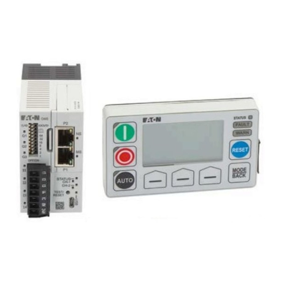
Eaton Power Xpert C445 User Manual (436 pages)
Global Motor Management Relay
Brand:
Eaton
| Category:
Relays
| Size: 6 MB
Table of Contents
Table of Contents
5
Definitions and Symbols
14
Hazardous High Voltage
14
Warnings and Cautions
14
Chapter 1-Power Xpert C445 Overview
15
System Overview
15
Catalog Numbering
16
Figure 1. C445 System Catalog Numbering
16
Figure 2. Base Control Module Catalog Numbering
16
Figure 3. Measurement Module Catalog Numbering
16
Figure 4. User Interface Catalog Numbering
17
Figure 5. Optional High Resistance Ground Fault Module and Cts
17
Figure 6. Optional Expansion I/O
17
Accessories
18
Table 1. Suggested Current Transformers
18
Table 2. Catalog Numbers: C445XC
18
Table 3. Catalog Numbers: D77E
18
Table 4. Catalog Numbers: C445XU
19
Table 5. Catalog Numbers: C445XS
19
Modules Overview
20
Figure 7. Base Control Module Image
20
Figure 8. Base Module Features and Connections-Front View
20
Figure 9. Base Module Features and Connections-Bottom View
21
Figure 10. Measurement Module Image
21
Figure 11. Measurement Module Features and Connections
21
Figure 12. C445UM Monitoring User Interface Image
22
Chapter 2-Receipt/Unpacking
23
General
23
Unpacking
23
Storage
23
Chapter 3-Installation And Wiring
24
Introduction
24
Mounting Positions
24
Figure 13. Vertical Position Limits
24
Clearance
25
Figure 14. Clearance Dimensions
25
C445 Module Assembly
26
Figure 15. Component Exploded View (C445B
26
Figure 16. Option Cover Removal
26
Figure 17. Real-Time Clock and Memory Backup Module Installation
27
Figure 18. Communication Card Installation
28
Figure 19. Component Mating
28
C445 Mounting
29
C445 Surface Mounting on DIN Rail
29
Figure 20. DIN-Rail Mounting Instructions
29
Figure 21. DIN Rail Dimensions
29
Table 6. Mounting Hardware
29
C445
30
Figure 22. Base Control Module-C445B
30
C445... Mounting Dimensions—Din Rail and Panel Mount
30
Figure 23. Measurement Module-C445MA
31
Figure 24. Stacked Base Control Module C445B
32
Figure 25. Measurement Module C445MB
33
Figure 26. Measurement Module C445MC
33
Monitoring User Interface C445UM Mounting Dimensions
34
Figure 27. User Interface-Monitoring Option
34
Figure 28. Panel Cutout Options
34
Figure 29. C445XG-MOD-C445 External Ground Fault Module
35
Figure 30. C445XG-CT2-28 MM Diameter Zero Sequencing Ground Fault CT
36
Figure 31. C445XG-CT3-52 MM Diameter Zero Sequencing Ground Fault CT
37
Figure 32. C445XG-CT4-63 MM Diameter Zero Sequencing Ground Fault CT
38
Figure 33. C445XG-CT7-80 X 175 Rectangular Zero Sequencing Ground Fault CT
39
Motor Wiring Connections-Typical
40
Figure 34. Terminal Fastening
40
Motor Connections for Standard Overload Control
41
Figure 35. Motor Connections for Standard Overload Control with C445BD
41
Figure 36. Motor Connections for Standard Overload Control with C445BA
42
Figure 37. XCT300-5, XCT600-5 (Inches)
43
Table 7. C445 CT Offering Catalog Numbers (XCT_ Cts)
43
Table 8. External CT Settings
44
Figure 38. External CT Wiring Diagram
45
Figure 39. Motor Connections for Standard Overload Control Using Potential Transformers with C445BD
46
Figure 40. Motor Connections for Standard Overload Control Using Potential Transformers with C445BA
47
Power and I/O Wiring
48
Figure 41. Base Control Module Features and Connections
48
Figure 42. Base Control Module LED Overview
49
Figure 43. Input Power Options
49
Figure 44. AC Field Input Terminal
50
Figure 45. 120 Vac Input Terminal Diagram
50
Figure 46. DC Field Input Terminal
51
Figure 47. DC Input Wiring Option 1 (Isolated)
51
Figure 48. DC Input Wiring Option 2 (Non-Isolated)
51
Digital Outputs
52
Figure 49. 4-Point Form a (NO) Output Connector
54
Figure 50. 3-Point Form C (NO/NC) Output Connector
54
Figure 51. Modbus Serial Connection
54
Figure 52. RS-485 Port
54
Base Control Module DIP Switches
55
Figure 53. Base Control Module DIP Switches with Built-In Modbus
55
Figure 54. Base Control Module DIP Switches with PROFIBUS Card
55
Figure 55. Base Control Module DIP Switches with Ethernet Card
55
Table 9. Modbus Data Rate
55
Figure 56. Measurement Module LED Overview
57
Table 10. PTC Sensor Status
57
Figure 57. C445 System Connection
58
Figure 58. C445 System Connection with Ground Fault Included
58
Chapter 4-System Configuration and Commissioning
59
Commissioning
59
Power Xpert Incontrol Commissioning Software Tool
63
Real-Time Clock and Memory Backup Module (RTC Module)
66
Parameter Lock Features
70
Chapter 5-System Configuration and Operation
77
Control Sources
77
Pre-Defined Operation Modes
78
Figure 59. C445UM: Monitoring User Interface
79
Table 11. Overload Only Configuration Parameters
80
Figure 60. Isolated 24 VDC Inputs/24 VDC Outputs/24 VDC Power
81
Figure 61. Non-Isolated 24 VDC Inputs/24 VDC Outputs/24 VDC C445 Power
81
Figure 62. 120 Vac Inputs and 120/230 Vac Outputs/C445 Power
82
Figure 63. Timing Diagram for the Direct Mode Operation
83
Figure 64. C445UM: Monitoring User Interface
83
Table 12. Direct Configuration Parameters
84
Figure 65. Isolated 24 VDC Inputs/24 VDC Outputs/24 VDC Power
85
Figure 66. Non-Isolated 24 VDC Inputs/24 VDC Outputs/24 VDC C445 Power
85
Figure 67. 120 Vac Inputs and 120/230 Vac Outputs/C445 Power
86
Figure 68. Timing Diagram for the Reverse Operation Mode
87
Figure 69. C445UM: Monitoring User Interface
87
Table 13. Reverser Configuration Parameters
88
Figure 70. Isolated 24 VDC Inputs/24 VDC Outputs/24 VDC Power
89
Figure 71. Non-Isolated 24 VDC Inputs/24 VDC Outputs/24 VDC C445 Power
89
Figure 72. 120 Vac Inputs and 120/230 Vac Outputs/C445 Power
90
Figure 73. Timing Diagram for the Star/Delta Operation Mode
91
Figure 74. C445UM: Monitoring User Interface
91
Table 14. Star/Delta Configuration Parameters
92
Figure 75. Isolated 24 VDC Inputs/24 VDC Outputs/24 VDC Power
93
Figure 76. Non-Isolated 24 VDC Inputs/24 VDC Outputs/24 VDC C445 Power
93
Figure 77. 120 Vac Inputs and 120/230 Vac Outputs/C445 Power
94
Figure 78. Timing Diagram for the Two Speed Operation Mode
95
Figure 79. C445UM: Monitoring User Interface
95
Table 15. Two Speed Two Winding Configuration Parameters
96
Figure 80. Isolated 24 VDC Inputs/24 VDC Outputs/24 VDC Power
97
Figure 81. Non-Isolated 24 VDC Inputs/24 VDC Outputs/24 VDC C445 Power
97
Figure 82. 120 Vac Inputs and 120/230 Vac Outputs/C445 Power
98
Figure 83. Timing Diagram for the Two Speed Dahlander Operation Mode
99
Figure 84. C445UM: Monitoring User Interface
99
Table 16. Two Speed Dahlander Configuration Parameters
100
Figure 85. Isolated 24 VDC Inputs/24 VDC Outputs/24 VDC Power
101
Figure 86. Non-Isolated 24 VDC Inputs/24 VDC Outputs/24 VDC C445 Power
101
Figure 87. 120 Vac Inputs and 120/230 Vac Outputs/C445 Power
102
Figure 88. Timing Diagram for the Auto Transformer Operation Mode
103
Figure 89. C445UM: Monitoring User Interface
103
Table 17. Auto Transformer Configuration Parameters
104
Figure 90. Isolated 24 VDC Inputs/24 VDC Outputs/24 VDC Power
105
Figure 91. Non-Isolated 24 VDC Inputs/24 VDC Outputs/24 VDC C445 Power
105
Figure 92. 120 Vac Inputs and 120/230 Vac Outputs/C445 Power
106
Figure 93. Timing Diagram for the Solenoid Valve Operation Mode
107
Figure 94. C445UM: Monitoring User Interface
107
Table 18. Solenoid Configuration Parameters
108
Figure 95. Isolated 24 VDC Inputs/24 VDC Outputs/24 VDC Power
110
Figure 96. Non-Isolated 24 VDC Inputs/24 VDC Outputs/24 VDC C445 Power
110
Figure 97. 120 Vac Inputs and 120/230 Vac Outputs/C445 Power
111
Figure 98. Timing Diagram for MCCB Feeder Operation Mode
112
Figure 99. C445UM: Monitoring User Interface
112
Table 19. MCCB Configuration Parameters
113
Figure 100. Isolated 24 VDC Inputs/24 VDC Outputs/24 VDC Power
114
Figure 101. Non-Isolated 24 VDC Inputs/24 VDC Outputs/24 VDC C445 Power
114
Figure 102. 120 Vac Inputs and 120/230 Vac Outputs/C445 Power
115
Figure 103. Timing Diagram for the Contactor Feeder Operating Mode
116
Figure 104. C445UM: Monitoring User Interface
116
Table 20. Contactor Feeder Configuration Parameters
117
Figure 105. Isolated 24 VDC Inputs/24 VDC Outputs/24 VDC Power
118
Figure 106. Non-Isolated 24 VDC Inputs/24 VDC Outputs/24 VDC C445 Power
118
Figure 107. 120 Vac Inputs and 120/230 Vac Outputs/C445 Power
119
Table 21. Configuration Parameter
120
Figure 108. C445UM: Monitoring User Interface
122
Table 22. Stand Alone Ground Fault Module Configuration Parameters
123
Chapter 6-Motor Protection
124
Introduction
124
Configuration Parameter Locking
124
Fault Trip, Fault no Trip and Fault Warning
125
Motor Control Operation
125
Start Cycle and Transition Timing
125
Motor Thermal Overload
126
Figure 109. Start Cycle and Transition Timing
126
Table 23. Parameters that Control the Transition Profile
126
Figure 110. Overload Trip Curves-Cold Coil (-40 °C to +60 °C)
127
Figure 111. Overload Trip Curves-Hot Coil (-40 °C to +60 °C)
128
Application Configuration
130
Table 24. Basic Parameters
130
Table 25. Advanced Parameters
130
Overview of Protection Features
131
Table 26. Current Based Protections
132
Table 27. Voltage Based Protections
133
Table 28. Power Based Protections
133
Advanced Protection
134
Table 29. Undervoltage
134
Table 30. Voltage Loss Restart
134
Figure 112. Example #1: Auto-Time-Mains Voltage Returns
136
Figure 113. Example #2: Auto-Time-Mains Voltage Does Not Return
137
Figure 114. Example #3: Short-Time-Mains Voltage Returns
138
Figure 115. Example #4: Short-Time-Mains Voltage Does Not Return
139
Figure 116. Example #5: Long-Time-Mains Voltage Returns
140
Figure 117 . Example #6: Long-Time-Mains Voltage Does Not Return
141
Advanced Protection Parameters
142
Table 31. Protections
142
Motor Protection
143
Table 32. Fault Warnings
143
Table 33. Overload
144
Table 34. Instantaneous Overcurrent
144
Table 35. Jam
145
Table 36. Stall
145
Table 37. Current Unbalance
145
Table 38. Current Phase Loss
146
Table 39. Undercurrent
146
Supply Protection
147
Table 40. Ground Fault
147
Table 41. Undervoltage
148
Table 42. Overvoltage
148
Table 43. Voltage Unbalance
149
Table 44. Voltage Phase Loss
149
Table 45. Voltage Phase Rotation
150
Table 46. PF Deviation
150
Table 47. Hz Dev - Slow
151
Table 48. Hz Dev - Fast
151
Load Protection
152
Table 49. Undercurrent
152
Table 50. Low Power
152
Table 51. High Power
153
Table 52. Peak Demand
153
Chapter 7-Monitoring And Diagnostics
154
Methods for Monitoring
154
Monitoring Parameters
155
Table 53. Current Based Monitoring
155
Table 54. Voltage Based Monitoring
155
Table 56. System Monitoring
156
Table 55. Power-Based Monitoring
156
Table 58. Trip Snapshot Parameters
157
Table 57. Faults and Events
157
Table 59. PTC Status Bits
157
Table 60. Motor Control Status Bits
157
Table 61. Active Fault, Warning and Inhibit Values
158
Chapter 8-C445Um Monitoring User Interface
160
C445UM Overview
160
Figure 118. C445UM
160
Table 62. C445UM Catalog Numbers
160
C445UM Setup Wizard
161
Figure 119. C445UM Setup Wizard
161
Table 63. C445UM Setup Wizard Parameters
161
C445UM LED and Button Overview
162
Figure 120. C445UM LED and Buttons
162
C445UM Monitoring
163
Figure 121. C445UM Monitoring Menus
163
Figure 122. Monitoring Menu Data
163
C445UM PRG Menu (Customizing Settings)
164
Figure 123. C445UM Program Menu
164
Customizing Settings in PRG Menu
165
Table 64. Program Menu Groups
165
C445UM Fault and Event Diagnostics
166
Figure 124. C445UM Diagnostics
166
Figure 125. C445UM Faults and Events
166
Figure 126. C445UM Inhibits
167
C445UM User Interface Settings
168
Figure 127. C445UM Control Button Disabled Notification Screen
168
Table 65. Running/Stopped/Auto LED Color Settings
168
C445UM Security
169
C445UM Services
169
Chapter 9-C445 Logic Engine and Expansion I/O
170
Power Xpert Incontrol Logic Engine
170
The Function Blocks
172
Accessing C445 System Parameters with the Logic Engine
206
C445 Expansion Inputs and Outputs
207
Expansion I/O Pass-Through to Fieldbus Networks
213
Ethernet/Ip
214
Profibus
215
Assigning I/O Parameters to Cyclic Modules
217
Modbus TCP and RS-485 Modbus
218
Chapter 10-C445 Ground Fault Monitoring and Protection
222
Ground Fault Monitoring Methods
222
Table 66. Residual Ground Fault Parameterization
222
Table 67. Zero-Sequence Ground Fault Parameterization
223
Table 68. C445 Zero-Sequence Current Transformers
223
Table 69. Pulse Detection Protection Parameterization
225
Appendix A-Technical Data and Specifications
226
Technical Data and Specifications
226
Table 70. Environmental Specifications
226
Table 71. Power Supply Specifications Summary
226
Table 72. Input/Output Specifications
227
Table 73. PTC Specifications
227
Table 74. Measurement Module Specifications
228
Table 75. Measurement Module Frame Breaks
228
Table 76. EMC Emissions
228
Table 77. EMC Immunity
229
Table 78. Agency Certifications and Regulatory
229
Table 79. Physical Size Specifications
230
Table 80. Short Circuit Ratings (North American CSA and UL)
230
Table 81. Short Circuit Ratings (IEC)
230
Table 82. Impulse Withstand Ratings
231
Appendix B-Troubleshooting and Diagnostics
232
Troubleshooting and Diagnostics
232
Table 83. Motor Protection Fault Definitions
232
Table 84. Load Protection Fault Definitions
233
Table 85. Line Protection Fault Definitions
234
Appendix C-Optional Communication Cards
235
Ethernet Card (C445XC-E)
235
Figure 128. C445 Ethernet Star Network Connection Example
235
Figure 129. C445 Ethernet Ring Network Connection Example
235
Figure 130. C445 Ethernet Linear Network Connection Example
235
Figure 131. Installing the Ethernet Communication Card
235
Ethernet Communication Card and DIP Switches
236
Figure 132. Base Control Module DIP Switches with Ethernet Card
236
LED Status Indicators
238
Table 86. Module Status Indicator
238
Table 87. Network Status Indicator
238
Ethernet LED Indications
239
Configuration Using a Web Browser
239
Table 88. Ethernet LED Description
239
Table 89. Five Levels of Authorization
239
Configuration Using an EDS File
240
Configuring Using the Incontrol Software Tool
240
Ethernet/Ip Protocol
240
Table 90. Ethernet/Ip Object Model for the C445 Motor Management Relay
240
Object Details
241
Table 91. Identity Object-Class 0X01
241
Table 92. Message Router Object-Class 0X2
242
Table 93. Assembly Object-Class 0X4
243
Table 94. C445 Assembly Object Instances
243
Table 95. Connection Manager Object-Class 0X6
275
Table 96. Discrete Input Object-Class 0X8
276
Table 97. Discrete Output Object-Class 0X9
277
Table 98. Control Supervisor Object-Class 0X29
278
Table 99. Overload Object-Class 0X2C
284
Table 100. System Component Definition Object-Class 0X88
285
Table 101. Voltage Object-Class 0X93
286
Table 102. Dynamic Input Assembly Interface Object-Class 0X96
288
Table 103. Dynamic Input Assembly Instance Parameters
289
Table 104. Motor Info Object-Class 0X9B
290
Table 105. Operation Mode Object-Class 0X9F
290
Table 106. Modbus Object-Class 0Xa0
291
Table 107 . Motor Monitoring Object-Class 0Xa1
293
Table 108. Motor Protection Object-Class 0Xa2
293
Table 109. Snapshot Object-Class 0Xa5
297
Table 111. RTC Object-Class 0Xb0
298
Table 110. Parameter Access Object-Class 0Xaa
298
Table 112. BCM Object-Class 0Xb1
299
Table 113. Option Card Object-Class 0Xb3
300
Table 114. Port Object-Class 0Xf4
301
Table 115. TCP/IP Object-Class 0Xf5
302
Table 116. Ethernet Link Object-Class 0Xf6
303
Modbus TCP Protocol
305
Table 117 . Modbus TCP Function Codes
305
PROFIBUS Communication Card
306
Figure 133. Installing the PROFIBUS Communication Card
306
Figure 134. Base Control Module DIP Switches with PROFIBUS Card
307
Table 118. Modbus Data Rate
307
Table 119. PROFIBUS D-Shell Connector Specifications
307
Table 120. DB-9 Connector
307
C445 Cyclic (Polling)
308
Table 121. PROFIBUS Card LED Definitions
308
PROFIBUS Diagnostics
312
Table 122. C445 Diagnostic Telegram Details
312
C445 PROFIBUS Configuration File
313
Table 123. PROFIBUS Configuration File
313
C445 PROFIBUS Bit Mapping Parameters
314
Table 124. Bit Mapping Parameters for Cyclic/Acyclic Writeable Parameters
314
Table 125. Fieldbus Motor Control Bits
314
Table 126. Bit Mapping Parameters for Cyclic/Acyclic Readable Parameters
314
Table 127 . PROFIBUS Cyclic/Acyclic Readable Parameters
315
Appendix D-Modbus Register Map
316
C445 Modbus Register Map
316
Table 128. C445 Modbus Register Map
316
Appendix E-Licenses
432
Licenses
432
Advertisement
Eaton Power Xpert C445 User Manual (317 pages)
Global Motor Management Relay
Brand:
Eaton
| Category:
Relays
| Size: 7 MB
Table of Contents
Table of Contents
4
Definitions and Symbols
13
Hazardous High Voltage
13
Warnings and Cautions
13
Chapter 1-Power Xpert C445 Overview
14
System Overview
14
Catalog Numbering
15
Figure 1. C445 System Catalog Numbering
15
Figure 2. Base Control Module Catalog Numbering
15
Figure 3. Measurement Module Catalog Numbering
15
Figure 4. User Interface Catalog Numbering
16
Figure 5. Control User Interface Overlay Example: NEMA
17
Table 1. Control User Interface Family-NEMA Color Scheme Options (English)
17
Figure 6. Control User Interface Overlay Examples: IEC
18
Table 2. Control User Interface Family-IEC Color Scheme (Symbols)
18
Accessories
19
Table 3. Suggested Current Transformers
19
Table 4. Catalog Numbers: C445XC
19
Table 5. Catalog Numbers: D77E
19
Table 6. Catalog Numbers: C445XU
20
Table 7. Catalog Numbers: C445XS
20
Modules Overview
21
Figure 7. Base Control Module Image
21
Figure 8. Base Module Features and Connections-Front View
21
Figure 9. Base Module Features and Connections-Bottom View
22
Figure 10. Measurement Module Image
22
Figure 11. Measurement Module Features and Connections
22
Figure 12. C445UM Monitoring User Interface Image
23
Figure 13. Control User Interface Image
24
Figure 14. Control User Interface Features and Connections
24
Chapter 2-Receipt/Unpacking
26
General
26
Unpacking
26
Storage
26
Chapter 3-Installation And Wiring
27
Introduction
27
Mounting Positions
27
Figure 15. Vertical Position Limits
27
Clearance
28
Figure 16. Clearance Dimensions
28
C445 Module Assembly
29
Figure 17. Component Exploded View (C445B
29
Figure 18. Option Cover Removal
29
Figure 19. Real-Time Clock and Memory Backup Module Installation
30
Figure 20. Communication Card Installation
31
Figure 21. Component Mating
31
C445 Mounting
32
C445 Surface Mounting on DIN Rail
32
Figure 22. DIN-Rail Mounting Instructions
32
Figure 23. DIN Rail Dimensions
32
Table 8. Mounting Hardware
32
C445
33
Figure 24. Base Control Module-C445B
33
C445... Mounting Dimensions—Din Rail and Panel Mount
33
Figure 25. Measurement Module-C445MA
34
Figure 26. Stacked Base Control Module C445B
35
Figure 27. Measurement Module C445MB
36
Figure 28. Measurement Module C445MC
36
Monitoring User Interface C445UM Mounting Dimensions
37
Figure 29. User Interface-Monitoring Option
37
Figure 30. Panel Cutout Options
37
Figure 31. Control User Interface C445UC
38
Motor Wiring Connections-Typical
39
Figure 32. Terminal Fastening
39
Motor Connections for Standard Overload Control
40
Figure 33. Motor Connections for Standard Overload Control with C445BD
40
Figure 34. Motor Connections for Standard Overload Control with C445BA
41
Figure 35. XCT300-5, XCT600-5 (Inches)
42
Table 9. C445 CT Offering Catalog Numbers (XCT_ Cts)
42
Table 10. External CT Settings
43
Figure 36. External CT Wiring Diagram
44
Figure 37. Motor Connections for Standard Overload Control Using Potential Transformers with C445BD
45
Figure 38. Motor Connections for Standard Overload Control Using Potential Transformers with C445BA
46
Power and I/O Wiring
47
Figure 39. Base Control Module Features and Connections
47
Figure 40. Base Control Module LED Overview
48
Figure 41. Input Power Options
48
Figure 42. AC Field Input Terminal
49
Figure 43. 120 Vac Input Terminal Diagram
49
Figure 44. DC Field Input Terminal
50
Figure 45. DC Input Wiring Option 1 (Isolated)
50
Figure 46. DC Input Wiring Option 2 (Non-Isolated)
50
Digital Outputs
51
Figure 47. 4-Point Form a (NO) Output Connector
53
Figure 48. 3-Point Form C (NO/NC) Output Connector
53
Figure 49. Modbus Serial Connection
53
Figure 50. RS-485 Port
53
Base Control Module DIP Switches
54
Figure 51. Base Control Module DIP Switches with Built-In Modbus
54
Figure 52. Base Control Module DIP Switches with PROFIBUS Card
54
Figure 53. Base Control Module DIP Switches with Ethernet Card
54
Table 11. Modbus Data Rate
54
Figure 54. Measurement Module LED Overview
56
Table 12. PTC Sensor Status
56
Figure 55. Control User Interface Digital Inputs
57
Figure 56. Control User Interface Input Connector Wiring
57
Figure 57. Control User Interface Leds
58
Table 13. User Defined LED Options for the Control User Interface
59
Chapter 4-System Configuration and Commissioning
60
Commissioning
60
Power Xpert Incontrol Commissioning Software Tool
64
Real-Time Clock and Memory Backup Module (RTC Module)
67
Parameter Lock Features
71
Chapter 5-System Configuration and Operation
78
Control Sources
78
Pre-Defined Operation Modes
79
Figure 58. C445UM: Monitoring User Interface
80
Figure 59. C445UC-I9: IEC Control and Status
80
Figure 60. C445UC-I1: IEC Status Only
80
Figure 61. C445UC-N9: NEMA Control and Status
80
Table 14. Overload Only Configuration Parameters
81
Figure 62. Isolated 24 VDC Inputs/24 VDC Outputs/24 VDC Power
82
Figure 63. Non-Isolated 24 VDC Inputs/24 VDC Outputs/24 VDC C445 Power
82
Figure 64. 120 Vac Inputs and 120/230 Vac Outputs/C445 Power
83
Figure 65. Timing Diagram for the Direct Mode Operation
84
Figure 66. C445UM: Monitoring User Interface
84
Figure 67. C445UC-I0: IEC Control and Status
84
Figure 68. C445UC-I1: IEC Status Only
84
Figure 69. C445UC-I4: IEC Control and Status
85
Figure 70. C445UC-N0: NEMA Control and Status
85
Figure 71. C445UC-N1: NEMA Status Only
85
Figure 72. C445UC-N4: NEMA Control and Status
85
Table 15. Direct Configuration Parameters
86
Figure 73. Isolated 24 VDC Inputs/24 VDC Outputs/24 VDC Power
87
Figure 74. Non-Isolated 24 VDC Inputs/24 VDC Outputs/24 VDC C445 Power
87
Figure 75. 120 Vac Inputs and 120/230 Vac Outputs/C445 Power
88
Figure 77. C445UM: Monitoring User Interface
89
Figure 78. C445UC-I3: IEC Control and Status
89
Figure 79. C445UC-I5: IEC Control and Status
89
Figure 80. C445UC-N2: NEMA Status Only
90
Figure 81. C445UC-N5: NEMA Control and Status
90
Table 16. Reverser Configuration Parameters
91
Figure 82. Isolated 24 VDC Inputs/24 VDC Outputs/24 VDC Power
92
Figure 83. Non-Isolated 24 VDC Inputs/24 VDC Outputs/24 VDC C445 Power
92
Figure 84. 120 Vac Inputs and 120/230 Vac Outputs/C445 Power
93
Figure 85. Timing Diagram for the Star/Delta Operation Mode
94
Figure 86. C445UM: Monitoring User Interface
94
Figure 87. C445UC-I0: IEC Control and Status
94
Figure 88. C445UC-I1: IEC Status Only
94
Figure 89. C445UC-I4: IEC Control and Status
94
Figure 90. C445UC-N0: NEMA Control and Status
95
Figure 91. C445UC-N1: NEMA Status Only
95
Figure 92. C445UC-N4: NEMA Control and Status
95
Table 17 . Star/Delta Configuration Parameters
96
Figure 93. Isolated 24 VDC Inputs/24 VDC Outputs/24 VDC Power
97
Figure 94. Non-Isolated 24 VDC Inputs/24 VDC Outputs/24 VDC C445 Power
97
Figure 95. 120 Vac Inputs and 120/230 Vac Outputs/C445 Power
98
Figure 96. Timing Diagram for the Two Speed Operation Mode
99
Figure 97. C445UM: Monitoring User Interface
100
Figure 98. C445UC-I2: IEC Control and Status
100
Figure 99. C445UC-I6: IEC Control and Status
100
Figure 100. C445UC-N3: NEMA Status Only
100
Figure 101. C445UC-N6: NEMA Control and Status
100
Table 18. Two Speed Two Winding Configuration Parameters
101
Figure 102. Isolated 24 VDC Inputs/24 VDC Outputs/24 VDC Power
102
Figure 103. Non-Isolated 24 VDC Inputs/24 VDC Outputs/24 VDC C445 Power
102
Figure 104. 120 Vac Inputs and 120/230 Vac Outputs/C445 Power
103
Figure 105. Timing Diagram for the Two Speed Dahlander Operation Mode
104
Figure 106. C445UM: Monitoring User Interface
105
Figure 107. C445UC-I2: IEC Control and Status
105
Figure 108. C445UC-I6: IEC Control and Status
105
Figure 109. C445UC-N3: NEMA Status Only
105
Figure 110. C445UC-N6: NEMA Control and Status
105
Table 19. Two Speed Dahlander Configuration Parameters
106
Table 24. Configuration Parameter
106
Figure 111. Isolated 24 VDC Inputs/24 VDC Outputs/24 VDC Power
107
Figure 112. Non-Isolated 24 VDC Inputs/24 VDC Outputs/24 VDC C445 Power
107
Figure 113. 120 Vac Inputs and 120/230 Vac Outputs/C445 Power
108
Figure 114. Timing Diagram for the Auto Transformer Operation Mode
109
Figure 115. C445UM: Monitoring User Interface
109
Figure 116. C445UC-I0: IEC Control and Status
109
Figure 117. C445UC-I1: IEC Status Only
109
Figure 118. C445UC-I4: IEC Control and Status
110
Figure 119. C445UC-N0: NEMA Control and Status
110
Figure 120. C445UC-N1: NEMA Status Only
110
Figure 121. C445UC-N4: NEMA Control and Status
110
Table 20. Auto Transformer Configuration Parameters
111
Figure 122. Isolated 24 VDC Inputs/24 VDC Outputs/24 VDC Power
112
Figure 123. Non-Isolated 24 VDC Inputs/24 VDC Outputs/24 VDC C445 Power
112
Figure 124. 120 Vac Inputs and 120/230 Vac Outputs/C445 Power
113
Figure 126. C445UM: Monitoring User Interface
114
Figure 127. C445UC-I0: IEC Control and Status
115
Figure 128. C445UC-I4: IEC Control and Status
115
Figure 129. C445UC-N0: NEMA Control and Status
115
Figure 130. C445UC-N4: NEMA Control and Status
115
Table 21. Solenoid Configuration Parameters
116
Figure 131. Isolated 24 VDC Inputs/24 VDC Outputs/24 VDC Power
118
Figure 132. Non-Isolated 24 VDC Inputs/24 VDC Outputs/24 VDC C445 Power
118
Figure 133. 120 Vac Inputs and 120/230 Vac Outputs/C445 Power
119
Figure 134. Timing Diagram for MCCB Feeder Operation Mode
120
Figure 135. C445UM: Monitoring User Interface
121
Figure 136. C445UC-I7: IEC Control and Status
121
Figure 137. C445UC-I8: IEC Control and Status
121
Figure 138. C445UC-N7: NEMA Control and Status
121
Figure 139. C445UC-N8: NEMA Control and Status
121
Table 22. MCCB Configuration Parameters
122
Figure 140. Isolated 24 VDC Inputs/24 VDC Outputs/24 VDC Power
123
Figure 141. Non-Isolated 24 VDC Inputs/24 VDC Outputs/24 VDC C445 Power
123
Figure 142. 120 Vac Inputs and 120/230 Vac Outputs/C445 Power
124
Figure 143. Timing Diagram for the Contactor Feeder Operating Mode
125
Figure 144. C445UM: Monitoring User Interface
125
Figure 145. C445UC-I7: IEC Control and Status
125
Figure 146. C445UC-I8: IEC Control and Status
125
Figure 147. C445UC-N7: NEMA Control and Status
126
Figure 148. C445UC-N8: NEMA Control and Status
126
Table 23. Contactor Feeder Configuration Parameters
127
Figure 149. Isolated 24 VDC Inputs/24 VDC Outputs/24 VDC Power
128
Figure 150. Non-Isolated 24 VDC Inputs/24 VDC Outputs/24 VDC C445 Power
128
Figure 151. 120 Vac Inputs and 120/230 Vac Outputs/C445 Power
129
Chapter 6-Motor Protection
132
Introduction
132
Configuration Parameter Locking
132
Fault Trip and Fault Warning
133
Motor Control Operation
133
Start Cycle and Transition Timing
133
Motor Thermal Overload
134
Figure 152. Start Cycle and Transition Timing
134
Table 25. Parameters that Control the Transition Profile
134
Figure 153. Overload Trip Curves-Cold Coil (-40 °C to +60 °C)
135
Figure 154. Overload Trip Curves-Hot Coil (-40 °C to +60 °C)
136
Application Configuration
138
Table 26. Basic Parameters
138
Table 27. Advanced Parameters
138
Overview of Protection Features
139
Table 28. Current Based Protections
140
Table 29. Voltage Based Protections
141
Table 30. Power Based Protections
141
Advanced Protection
142
Table 31. Undervoltage
142
Table 32. Voltage Loss Restart
142
Figure 155. Example #1: Auto-Time-Mains Voltage
144
Figure 156. Example #2: Auto-Time-Mains Voltage Does Not Return before Auto Time Expires
145
Figure 157 . Example #3: Short-Time-Mains Voltage
146
Figure 158. Example #4: Short-Time-Mains Voltage Does Not Return before Short Time Expires
147
Figure 159. Example #5: Long-Time-Mains Voltage
148
Figure 160. Example #6: Long-Time-Mains Voltage Does Not Return before Long Time Expires
149
Advanced Protection Parameters
150
Table 33. Protections
150
Motor Protection
151
Table 34. Fault Warnings
151
Table 35. Overload
152
Table 36. Instantaneous Overcurrent
152
Table 37. Jam
153
Table 38. Stall
153
Table 39. Current Unbalance
153
Table 40. Current Phase Loss
154
Table 41. Undercurrent
154
Supply Protection
155
Table 42. Ground Fault
155
Table 43. Undervoltage
156
Table 44. Overvoltage
156
Table 45. Voltage Unbalance
157
Table 46. Voltage Phase Loss
157
Table 47. Voltage Phase Rotation
158
Table 48. PF Deviation
158
Table 49. Hz Dev - Slow
159
Table 50. Hz Dev - Fast
159
Load Protection
160
Table 51. Undercurrent
160
Table 52. Low Power
160
Table 53. High Power
161
Table 54. Peak Demand
161
Chapter 7-Monitoring And Diagnostics
162
Methods for Monitoring
162
Monitoring Parameters
163
Table 55. Current Based Monitoring
163
Table 56. Voltage Based Monitoring
163
Table 58. System Monitoring
164
Table 57 . Power-Based Monitoring
164
Table 60. Trip Snapshot Parameters
165
Table 59. Faults and Events
165
Table 61. PTC Status Bits
165
Table 62. Motor Control Status Bits
165
Table 63. Active Fault, Warning and Inhibit Values
166
Chapter 8-C445Um Monitoring User Interface
168
C445UM Overview
168
Figure 161. C445UM
168
Table 64. C445UM Catalog Numbers
168
C445UM Setup Wizard
169
Figure 162. C445UM Setup Wizard
169
Table 65. C445UM Setup Wizard Parameters
169
C445UM LED and Button Overview
170
Figure 163. C445UM LED and Buttons
170
C445UM Monitoring
171
Figure 164. C445UM Monitoring Menus
171
Figure 165. Monitoring Menu Data
171
C445UM PRG Menu (Customizing Settings)
172
Figure 166. C445UM Program Menu
172
Customizing Settings in PRG Menu
173
Table 66. Program Menu Groups
173
C445UM Fault and Event Diagnostics
174
Figure 167. C445UM Diagnostics
174
Figure 168. C445UM Faults and Events
174
Figure 169. C445UM Inhibits
175
C445UM User Interface Settings
176
Figure 170. C445UM Control Button Disabled Notification Screen
176
Table 67 . Running/Stopped/Auto Leds Color Settings
176
C445UM Security
177
C445UM Services
177
Appendix A-Technical Data and Specifications
178
Technical Data and Specifications
178
Table 68. Environmental Specifications
178
Table 69. Power Supply Specifications Summary
178
Table 70. Input/Output Specifications
179
Table 71. PTC Specifications
179
Table 72. Measurement Module Specifications
180
Table 73. Measurement Module Frame Breaks
180
Table 74. EMC Emissions
180
Table 75. EMC Immunity
181
Table 76. Agency Certifications and Regulatory
181
Table 77. Physical Size Specifications
182
Table 78. Short Circuit Ratings (North American CSA and UL)
182
Table 79. Short Circuit Ratings (IEC)
182
Table 80. Impulse Withstand Ratings
183
Appendix B-Troubleshooting and Diagnostics
184
Troubleshooting and Diagnostics
184
Table 81. Motor Protection Fault Definitions
184
Table 82. Load Protection Fault Definitions
185
Table 83. Line Protection Fault Definitions
186
Appendix C-Optional Communication Cards
187
Ethernet Card (C445XC-E)
187
Figure 171. C445 Ethernet Star Network Connection Example
187
Figure 172. C445 Ethernet Ring Network Connection Example
187
Figure 173. C445 Ethernet Linear Network Connection Example
187
Figure 174. Installing the Ethernet Communication Card
187
Ethernet Communication Card and DIP Switches
188
Figure 175. Base Control Module DIP Switches with Ethernet Card
188
LED Status Indicators
190
Table 84. Module Status Indicator
190
Table 85. Network Status Indicator
190
Ethernet LED Indications
191
Configuration Using a Web Browser
191
Table 86. Ethernet LED Description
191
Table 87. Five Levels of Authorization
191
Configuration Using an EDS File
192
Configuring Using the Incontrol Software Tool
192
Ethernet/Ip Protocol
192
Table 88. Ethernet/Ip Object Model for the C445 Motor Management Relay
192
Object Details
193
Table 89. Identity Object-Class 0X01
193
Table 90. Message Router Object-Class 0X2
194
Table 91. Assembly Object-Class 0X4
195
Table 92. C445 Assembly Object Instances
195
Table 93. Connection Manager Object-Class 0X6
206
Table 94. Discrete Input Object-Class 0X8
207
Table 95. Discrete Output Object-Class 0X9
208
Table 96. Control Supervisor Object-Class 0X29
209
Table 97 . Overload Object-Class 0X2C
216
Table 98. System Component Definition Object-Class 0X88
216
Table 99. Voltage Object-Class 0X93
217
Table 100. Dynamic Input Assembly Interface Object-Class 0X96
219
Table 101. Dynamic Input Assembly Instance Parameters
220
Table 102. Motor Info Object-Class 0X9B
221
Table 103. Operation Mode Object-Class 0X9F
221
Table 104. Modbus Object-Class 0Xa0
222
Table 105. Motor Monitoring Object-Class 0Xa1
223
Table 106. Motor Protection Object-Class 0Xa2
224
Table 107. Snapshot Object-Class 0Xa5
228
Table 109. RTC Object-Class 0Xb0
229
Table 108. Parameter Access Object-Class 0Xaa
229
Table 110. BCM Object-Class 0Xb1
230
Table 111. BUI Object-Class 0Xb2
231
Table 112. Option Card Object-Class 0Xb3
232
Table 113. Port Object-Class 0Xf4
233
Table 114. TCP/IP Object-Class 0Xf5
234
Table 115. Ethernet Link Object-Class 0Xf6
235
Modbus TCP Protocol
237
Table 116. Modbus TCP Function Codes
237
PROFIBUS Communication Card
238
Figure 176. Installing the PROFIBUS Communication Card
238
Figure 177. Base Control Module DIP Switches with PROFIBUS Card
239
Table 117 . Modbus Data Rate
239
Table 118. PROFIBUS D-Shell Connector Specifications
239
Table 119. DB-9 Connector
239
C445 Cyclic (Polling)
240
Table 120. PROFIBUS Card LED Definitions
240
PROFIBUS Diagnostics
243
Table 121. C445 Diagnostic Telegram Details
243
C445 PROFIBUS Configuration File
245
Table 122. PROFIBUS Configuration File
245
C445 PROFIBUS Bit Mapping Parameters
246
Table 123. Bit Mapping Parameters for Cyclic/Acyclic Writeable Parameters
246
Table 124. Fieldbus Motor Control Bits
246
Table 125. Bit Mapping Parameters for Cyclic/Acyclic Readable Parameters
246
Table 126. PROFIBUS Cyclic/Acyclic Readable Parameters
247
Appendix D-Modbus Register Map
248
C445 Modbus Register Map
248
Table 127. C445 Modbus Register Map
248
Appendix E-Safety Manual
315
Eex E Types of Protection
315
Eaton Power Xpert C445 Safety Manual (34 pages)
Global motor management relay
Brand:
Eaton
| Category:
Relays
| Size: 1 MB
Table of Contents
Support Services
3
Website
3
Website Address
3
Eatoncare Customer Support Center
3
Technical Resource Center-Automations and Communications
3
For Customers in Europe, Contact
3
Table of Contents
4
Safety Considerations
6
Definitions and Symbols
6
Hazardous High Voltage
6
Warnings and Cautions
6
About this Manual
7
Power Xpert® C445 Motor Management Relay
7
Power Xpert® C445 System Overview
8
Power Xpert® C445 Catalog Numbering
15
Protection and Monitoring
18
Motor Thermal Overload
18
Overload Trip Curve ( -40C to 60C )
18
Current Phase Loss
19
Residual Ground Fault
20
Reclosing
21
Stall
21
Overload Fieldbus Control Word
22
Safety Figures
23
Safety Functions
23
SIL Declaration of Conformity
23
Installation
26
Common Technical Data Related to EMI/EMC
27
Mounting
27
Typical Wiring Diagrams
27
Device Settings
28
Repair and Maintenance
26
Warranty
26
Test of the Relays
29
Operational Status Signaling
29
Base Control Module LED Behavior
30
Measurement Module LED Behavior
30
Proof Test
30
Proof Test with Motor off
30
Procedure
31
Conditions of Safe Use (Controlled by Eaton Drawing 464-1025)
32
Notes
33
Advertisement
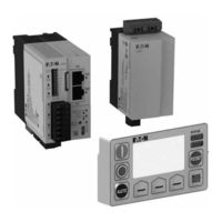
Eaton Power Xpert C445 Installation Leaflet (8 pages)
Base Control
Brand:
Eaton
| Category:
Control Unit
| Size: 3 MB
Table of Contents
Caution
2
C445B.... + C445M... + C445U... + D77E-QPIP ... System Configuration
4
C445B... Mounting and Dimensions
5
Modbus Baud Rate
6
C445B.... Connections
6
C445B… Input Voltage Power Consumption
7
Disclaimer of Warranties and Limitation of Liability
7
WARNING if MOTOR APPLICATION NEEDS INCREASED SAFETY [Ex E] PROTECTION
7
Catalog Number Certification
7
Eaton Power Xpert C445 Installation Leaflet (4 pages)
Brand:
Eaton
| Category:
Measuring Instruments
| Size: 1 MB
Table of Contents
C445M... Wiring
2
C445M... Connections
2
C445MA... Mounting and Dimentions
3
C445MB... Mounting and Dimentions
3
C445MC... Mounting and Dimentions
4
Disclaimer of Warranties and Limitation of Liability
4
Eaton Power Xpert C445 Manual (2 pages)
Brand:
Eaton
| Category:
Industrial Equipment
| Size: 0 MB
Table of Contents
24 VDC Display Stand Features
1
Using the Power Xpert Incontrol PC Tool
1
Initial Setup
2
Motor Control
2
Over Current Fault
2
Over Voltage Fault
2
Under Power Fault
2
Power down
2
Advertisement
Related Products
Eaton C440/XTOE
Eaton Cutler-Hammer Digitrip 3000
Eaton Cutler-Hammer DIGITRIP 3000 Series
Eaton C441R
Eaton C441T
Eaton C441 Series
Eaton C441U
Eaton C441V
Eaton C441Q
Eaton C441QS
Eaton Categories
UPS
Circuit breakers
Switch
Industrial Equipment
Industrial Electrical
More Eaton Manuals
Login
Sign In
OR
Sign in with Facebook
Sign in with Google
Upload manual
Upload from disk
Upload from URL