Eaton Cutler-Hammer MP-3000 Manual
Motor protection relay
Hide thumbs
Also See for Cutler-Hammer MP-3000:
- Instruction leaflet (103 pages) ,
- Instruction leaflet (100 pages)

Related Manuals for Eaton Cutler-Hammer MP-3000


Summary of Contents for Eaton Cutler-Hammer MP-3000
- Page 1 I.L. 17562 MP-3000 Motor Protection Relay Cutler-Hammer Power Management Products Center 240 Vista Park Drive Pittsburgh, PA 15205 1-800-809-2772 http:\\www.cutlerhammer.eaton.com Effective 8/99 Version PR 0.3...
-
Page 2: Table Of Contents
I.L. 17562 Page 2 TABLE OF CONTENTS Section 1 - Introduction … … … … … … … … … … … … … … … … … … … … … … … ... Section 2 - Product Overview …... -
Page 3: Introduction
Page 3 I.L. 17562 SECTION 1. INTRODUCTION 1.0 General The MP-3000 is an advanced microprocessor-based motor protection relay that is easy to set up and use. It monitors, controls and protects motors against overload, thermal damage to rotor or stator, electrical faults, and excessive starting, and many process equipment failures. Advanced algorithms and thermal models give safe operation over a wide range of conditions. - Page 4 I.L. 17562 Page 4 • Differential trip input • Emergency override clears blocks to motor restarting (if enabled) • Program settings while motor runs, with controlled changeover (if enabled) • Disarmed mode for commissioning and checking in a running process. 1.1 Replacing the IQ1000 II with MP-3000 The MP-3000 Motor Protection Relay has been designed to serve as a direct replacement for the prior-generation Westinghouse or Cutler-Hammer IQ 1000 II.
- Page 5 Page 5 I.L. 17562 12 Mechanical Process Load Shedding feature provides overload indication to control upstream processes, averting unnecessary motor overload shutdown or jam trips, and maintaining process continuity. 13 Download settings or retrieve metered and historical values via the communications port. 14 Flexible user-configurable inputs and outputs for broader application.
- Page 6 I.L. 17562 Page 6 The following accessories and options are covered in other instruction manuals: • Drawout case option I.L. [NUMBER IN FINAL I.L.] • URTD module for connecting I.L. 17367 RTDs to MP-3000 (1) • IQ DC Power Supply, 40-250 Vdc I.L.
-
Page 7: Product Overview
Page 7 I.L. 17562 SECTION 2. PRODUCT OVERVIEW 2.0 General Overview The MP-3000 Motor Protection Relay is available in either a fixed mount, semi-flush case or in a semi-flush Quick Release drawout case. Both housings are compact and fit a standard IQ cutout. The optional Quick Release drawout case features 2-stage contact disconnects and self-shorting Ct circuit terminal blocks. - Page 8 I.L. 17562 Page 8 The relay samples the current waveforms 36 times per cycle providing accurate measurements of the positive and negative sequence currents, as well as harmonic components which add to rotor and stator heating. The negative sequence component of current causes far greater heating effect on the rotor and has a greater impact on the thermal model in the relay, as compared to the balanced or positive-sequence component.
- Page 9 Page 9 I.L. 17562 2.2 Motor Starting and Control Functions The MP-3000 Motor Protection relay includes logic to control the number of starts that can occur on the motor in a given time period for cold and hot motor conditions. Settable timers are provided to control the time between starts and to restart a motor after a stop.
- Page 10 I.L. 17562 Page 10 2.2.7 Motor Starting Profile The MP-3000 records the average current versus time for the last four starting cycles. This information is available via the communications port. PowerNet host plots the motor current versus the motor cold-start protection curve as in Figure 2.1. 2.3 User Interface The MP-3000 Motor Protection Relay has a user-friendly interface that makes it easy to retrieve important information or to make setting changes.
-
Page 11: Specifications
Page 11 I.L. 17562 SECTION 3. MP3000 TECHNICAL SPECIFICATIONS Control Power Nominal voltage: 120 Vac or 240 Vac (+10%, -25%) Operating Range: 120 Vac: 66 - 132 Vac 240 Vac: 132 – 264 Vac Interruption ride through time: 30 cycle interruption of nominal ac supply. Frequency: 60 Hz nominal, 57-63 Hz 50 Hz nominal, 47-53 Hz... - Page 12 I.L. 17562 Page 12 Trip setting ranges Ground fault (GF): Off, 2% to 55% of Ct ratio primary GF start delay: 2 to 60 cycles GF run delay: 0 to 60 cycles ± 20 ms Timer accuracy: Instantaneous overcurrent: off, 300 to 1600 % FLA IOC start time delay: 2 to 60 cycles ±...
- Page 13 Page 13 I.L. 17562 IPONI Communications Type: 2 wire, 115.2 kHz carrier Baud Rate: 1200 ASK or 9600 FSK Max. distance: 10,000 feet Protocol: INCOM Functions: Read/write set points Read metered values Read trip/alarms Read events Read history Reset history Reset functions Emergency override Trip...
-
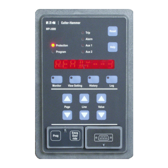
Page 14: Operator Panel
I.L. 17562 Page 14 SECTION 4. OPERATOR PANEL 4.0 General Description — The faceplate of the MP-3000 contains the display, indicators, and pushbuttons that make up the Operator Panel (Figures 4.1 and 4.2). The Operator Panel is used to: Monitor the metered values on the Display Window Enter or modify setpoint values or settings View motor history or statistics View a log of recent events... - Page 15 Page 15 I.L. 17562 In the Program mode, pressing the Reset pushbutton will allow the user to exit out of the Program mode without saving any entered setpoints. 4.0.7 Operator Panel LEDs — There are 10 LEDs on the operator panel. The Protection LED is lit when the MP-3000 is in the Protection mode.
- Page 16 I.L. 17562 Page 16 For example, to view the motor bearing temperatures: • Press the Monitor pushbutton; the display will show MONITOR as shown at the top of Table 4.2. • Press the Page up button once to advance to MONT I. •...
- Page 17 Page 17 I.L. 17562 4.5 Log Mode — The Log mode displays a record of detected events that have happened to the motor. The following are considered events: start, stop, entering into Program mode, using the emergency override button, alarm condition, and trip condition. Unlike the other modes, the Line column function order varies with the number of events, since the actual event information is stored as it happens.
- Page 18 I.L. 17562 Page 18 Figure 4.1 MP-3000 Pushbuttons PR 0.3 Effective 8/99...
- Page 19 Page 19 I.L. 17562 Figure 4.2 MP-3000 LED Indicators PR 0.3 Effective 8/99...
- Page 20 I.L. 17562 Page 20 Table 4.1 Motor State (Default Mode) Display Display Complete Help Message Description READY--1 READY TO START MOTOR, WARNING SINGLE PHASE TEST MODE MP-3000 has been set to 1 PHASE for bench testing only. Will not protect a 3-phase motor.
- Page 21 Page 21 I.L. 17562 Table 4.2 Monitor Mode Display Page Line Complete Help Message Description MONITOR MONITOR OF REAL TIME VALUES Monitor mode MONT I REAL TIME DATA FROM CURRENT Current monitoring data follows MEASUREMENTS IAVG XXX AVERAGE OF THREE PHASE CURRENT Average rms current of 3-phase currents in amps PHASE A CURRENT IN AMPS...
- Page 22 I.L. 17562 Page 22 Page Line Complete Help Message Description TUS XXX TIME IN MINUTES UNTIL NEXT START CAN Displays largest amount of time in OCCUR minutes among three functions: anti-backspin, starts per unit time, and time between starts RMST XX REMAINING STARTS Number of starts remaining if starts per time is programmed...
- Page 23 Page 23 I.L. 17562 Table 4.3 View Settings Mode/Program Worksheet Program Date __________ Control Schematic_________________________________________ Unit ID / Starter Type _________________________ Work Order # _______________________ Motor HP __________ Mfgr. __________ Serial # ______________Volts___________________ FLA __________ LRC ___________ Stall Time/LRT ____________Accel Time ______________ SF ___________________RTD Type __________________ Other ________________________...
- Page 24 I.L. 17562 Page 24 Line Display Help Message Setpoint Value as Selected Value Range/ Value shipped Selection MB T XXX MOTOR BEARING TRIP 0-199°C, OFF / 32-390°F, OFF (1°increments) MB A XXX MOTOR BEARING ALARM 0-199°C, OFF / 32-390°F, OFF (1°increments) LB T XXX LOAD BEARING TRIP...
- Page 25 Page 25 I.L. 17562 Line Display Help Message Setpoint Value as Selected Value Range/ Value shipped Selection UBTR XXX PHASE UNBALANCE TRIP 0-240 sec. (1 RUN DELAY IN SECONDS sec. increments) Page 4 SP ALARM SETPOINTS FOR ALARM SETTINGS GFA XXX GROUND FAULT ALARM 2-55% of Ground LEVEL IN % OF GROUND CT...
- Page 26 I.L. 17562 Page 26 Line Display Help Message Setpoint Value as Selected Value Range/ Value shipped Selection SECONDS ON DISCRETE increments) INPUT 2 Note: Choosing a time value here (not OFF) also locks P7L1 to INC SEQ and no other choices are available there.
- Page 27 Page 27 I.L. 17562 Line Display Help Message Setpoint Value as Selected Value Range/ Value shipped Selection ZERO SW DETECTION selected here, RST DBL – RESET DISABLE P5L11 will be EMG OVR – EMERGENCY forced to ZSW OVERRIDE ZERO SW – ZERO SPEED SWITCH If P5L11 was CONFIGURE DISCRETE...
- Page 28 I.L. 17562 Page 28 Line Display Help Message Setpoint Value as Selected Value Range/ Value shipped Selection JAM OFF Choose: ENABLE UNDERLOAD ALARM Toggles between UL A UL A OR TRIP TO ACTIVATE UL A ON, UL T UL T ALARM RELAY OUTPUT OR ON, and UL OFF DISABLE...
- Page 29 Page 29 I.L. 17562 Line Display Help Message Setpoint Value as Selected Value Range/ Value shipped Selection PH R OFF RELAY OUTPUT OR DISABLE PH R OFF INSQ ON ENABLE INCOMPLETE Toggles between INSQ OFF SEQUENCE TRIP TO INSQ ON and INSQ OFF ACTIVATE ALARM RELAY INSQ OFF...
- Page 30 I.L. 17562 Page 30 Line Display Help Message Setpoint Value as Selected Value Range/ Value shipped Selection Choose: ENABLE GROUND FAULT Toggles between GF OFF GF A ALARM OR TRIP TO GF A ON, GF T GF T ACTIVATE AUX1 RELAY ON, and GF OFF OUTPUT OR DISABLE Choose:...
- Page 31 Page 31 I.L. 17562 Line Display Help Message Setpoint Value as Selected Value Range/ Value shipped Selection AUX1 RELAY OUTPUT OR RTDF OFF RTDF OFF DISABLE RCOM ON ENABLE RTD MODULE Toggles between RCOM OFF COMMUNICATION FAILURE RCOM ON and RCOM TO ACTIVATE AUX1 RELAY RCOM OFF...
- Page 32 I.L. 17562 Page 32 Line Display Help Message Setpoint Value as Selected Value Range/ Value shipped Selection Choose: ENABLE I2T ALARM OR TRIP Toggles between I2T OFF I2T A ON TO ACTIVATE AUX2 RELAY I2T A ON, I2T T I2T T ON OUTPUT OR DISABLE ON, and I2T OFF...
- Page 33 Page 33 I.L. 17562 Line Display Help Message Setpoint Value as Selected Value Range/ Value shipped Selection IOC A ON ENABLE INSTANTANEOUS Toggles between IOCT OFF IOC T ON OVERCURRENT ALARM OR IOCT ON and TRIP TO ACTIVATE AUX2 IOCT OFF RELAY OUTPUT OR DISABLE PH R ENABLE PHASE REVERSAL...
- Page 34 I.L. 17562 Page 34 Line Display Help Message Setpoint Value as Selected Value Range/ Value shipped Selection ALARM RELAY ENERGIZES AL MODE2 ON ALARM EVENT OR MODE 2 – ALARM RELAY ENERGIZES ON POWER UP AND DE-ENERGIZES ON ALARM EVENT AX1 MOD CONFIGURE AUX1 RELAY Toggles between...
- Page 35 Page 35 I.L. 17562 Line Display Help Message Setpoint Value as Selected Value Range/ Value shipped Selection IQ2 EN – IQ1000II EMULATION IQ2 DIS – MP-3000 COMMUNICATION RLYF TRP INTERNAL DIAGNOSTIC Toggles between RLYF T+A RLYF ALM FAILURE ACTIVATES TRIP RLYF TRP, AND OR ALARM RELAY RLYF ALM and...
- Page 36 I.L. 17562 Page 36 Line Display Help Message Setpoint Value as Selected Value Range/ Value shipped Selection Reset button to perform selected test Choose: FORCE ANALOG OUTPUT Toggle between ----- ----- AOUT 4, AOUT 4 – FORCE A 4 MA OUTPUT AOUT 12, AND AOUT 12 –...
- Page 37 Page 37 I.L. 17562 Table 4.4 History Mode Display Note For any of the Line functions, the Value buttons are used to view the multiple displays. Page Line Display Complete Help Message Description HISTORY HISTORY MODE Recalls stored motor data HIST MTR HISTORY OF MOTOR STATISTICS This page contains historical...
- Page 38 I.L. 17562 Page 38 Page Line Display Complete Help Message Description RESET MM/DD/YY DATE OF RESET HH:MM:SS TIME OF RESET IOCT XX IOCT XX NUMBER OF INSTANTANEOUS OVER CURRENT TRIPS SINCE LAST RESET MM/DD/YY DATE OF RESET HH:MM:SS TIME OF RESET JAMT XX JAMT XX NUMBER OF JAM TRIPS SINCE...
- Page 39 Page 39 I.L. 17562 Page Line Display Complete Help Message Description TRIPS SINCE LAST RESET MM/DD/YY DATE OF RESET HH:MM:SS TIME OF RESET STXT XX STXT XX NUMBER OF STARTS PER TIME TRIPS SINCE LAST RESET MM/DD/YY DATE OF RESET HH:MM:SS TIME OF RESET TBST XX...
- Page 40 I.L. 17562 Page 40 Page Line Display Complete Help Message Description HIST ALM HISTORY OF ALARM EVENTS GF A XX GF A XX NUMBER OF GROUND FAULT Number of respective alarms ALARMS SINCE LAST RESET since last reset MM/DD/YY DATE OF RESET The date when respective alarm function was reset HH:MM:SS...
- Page 41 Page 41 I.L. 17562 Page Line Display Complete Help Message Description HIST TOT HISTORY TOTALS FOR MOTOR TRPS TOTAL NUMBER OF TRIPS SINCE MM/DD/YY RESET HH:MM DATE OF RESET TIME OF RESET TRT XXXX TOTAL RUN TIME SINCE RESET MM/DD/YY DATE OF RESET HH:MM TIME OF RESET...
- Page 42 I.L. 17562 Page 42 Table 4.5 Log Mode Display Page Line Value Complete Help Message Description LOG OF EVENTS MODE Recalls stored motor events as observed by the relay LOG BOOK OF THE LAST 100 This page contains a chronological BOOK EVENTS list of motor events...
- Page 43 Page 43 I.L. 17562 Page Line Value Complete Help Message Description the communication network. MM/DD/YY DATE OF EVENT The date that the event occurred HH.MM TIME OF EVENT The time that the event occurred TRIP (Description of trip event) For a complete list of trips with help messages see the trip conditions table 12.2, and internal diagnostics failure messages table...
- Page 44 I.L. 17562 Page 44 Page Line Value Complete Help Message Description OF EVENT" WT2 XXX WINDING TEMP 2 IN DEGREES (F OR C) AT TIME OF EVENT" WT3 XXX WINDING TEMP 3 IN DEGREES (F OR C) AT TIME OF EVENT" WT4 XXX WINDING TEMP 4 IN DEGREES (F OR C) AT TIME...
- Page 45 Page 45 I.L. 17562 Page Line Value Complete Help Message Description CURRENT TRANSITION IN current below the transition current SECONDS set point level TSTR XXX TIME FROM START TO RUN OR TRIP IN SECONDS PR 0.3 Effective 8/99...
-
Page 46: Programming The Mp-3000
I.L. 17562 Page 46 SECTION 5. PROGRAMMING THE MP-3000 5.0 General The Program mode is used to change MP-3000 setpoints. The user should read this section and also Section 9. Application and Settings, for a full understanding of the setpoints and the relay functions they control. This Section summarizes the functions of all of the setpoints. - Page 47 Page 47 I.L. 17562 Most of the following setpoints can be viewed by users without access to the Program button behind the front-panel security door. Use the View Settings display mode button. Note that certain setpoints without logical display values are not visible in the View Setpoints mode.
- Page 48 I.L. 17562 Page 48 NOTE This UTC setting is where the user considers the service factor rating of the motor. Never adjust the FLA setting P1L1 according to the service factor (see subsection 9.1.3.3). For normal use, set UTC to service factor times 100 %. The available range is 85% to 150%. The service factor is found on the motor nameplate or in manufacturer’...
- Page 49 Page 49 I.L. 17562 300 × 5/400 = 3.75 amperes, an ideal value. For a 1 ampere Ct set: For optimum metering accuracy at low loads, the Ct should deliver between 0.7 and 0.8 amperes at 100 percent FLA. Attempt to achieve 0.75 A. For reliable motor protection, the Ct should deliver between 0.5 and 0.8 amperes at 100 percent FLA.
- Page 50 I.L. 17562 Page 50 Ground fault protection by residual connection of phase Cts is possible, but doesn't give high sensitivity. See Section 9.1.10. 5.1.7 Setpoint P1L7, Frequency (FREQ) — Sets the MP-3000 for either a 60 Hz or 50 Hz ac supply frequency.
- Page 51 Page 51 I.L. 17562 Setpoint P2L1 above. There are six specifically-labeled stator RTD inputs on the URTD module whose readings can trigger this particular type of trip. See 9.1.8 for setting advice. CAUTION If WD T is set to OFF, the thermal-model protection reverts to the non-RTD algorithm even if a URTD is connected.
- Page 52 I.L. 17562 Page 52 There is one specifically-labeled auxiliary RTD input on the URTD module whose readings can trigger this particular type of alarm. 5.2.10 Setpoint P2L10, RTD Diagnostic (DIAG ON or DIAG OFF) — Sets the RTD diagnostic alarm ON or OFF. If set to ON, the relay will alarm on any RTD failure or URTD communications failure.
- Page 53 Page 53 I.L. 17562 5.3.3 Setpoint P3L3, Ground Fault Run Delay (GFRD) — Sets the number of power cycles that a ground fault trip or alarm operation must be maintained before the relay produces an output. 5.3.4 Setpoint P3L4, Instantaneous Overcurrent Trip Level (IOC) — Sets the instantaneous overcurrent trip limit in percent of FLA above which the relay will trip.
- Page 54 I.L. 17562 Page 54 5.3.10 Setpoint P3L10, Underload Start Delay (ULSD) — Sets the number of seconds after a start until the underload trip and alarm functions are enabled. 5.3.11 Setpoint P3L11, Underload Trip Run Delay (ULTR) — Sets the number of seconds that current below the underload trip setting must be maintained before a trip output.
- Page 55 Page 55 I.L. 17562 5.4.3 Setpoint P4L3, Jam Alarm Level (JMA) — Sets the current limit in percent of FLA at which the jam alarm picks up. This alarm can be set to OFF. Set to a lower level than the jam trip level P3L6.
- Page 56 I.L. 17562 Page 56 5.5.4 Setpoint P5L4, Number of Cold Starts Allowed (NOCS) — Sets the number of cold starts allowed from 1 to 5. Most motors can tolerate some number of consecutive cold starts before the time between starts is enforced. The MP-3000 treats a start as the first in a sequence of cold starts if the motor has been stopped for at least the time period which is the greatest of: •...
- Page 57 Page 57 I.L. 17562 expected time. If a problem develops later on, the report-back contact opens. In either case, the open contact state indicates that the motor should be tripped. To use this function, set a time limit for report-back here. Set P5L9, next, to define the start of report-back timing.
- Page 58 I.L. 17562 Page 58 This protection is always useful, but is essential if the Long Acceleration Time (LAT) function set by P5L10 is used. Note that if the ZSW function is set to ON, then Discrete Input 1 is automatically configured to be the zero speed switch input.
- Page 59 Page 59 I.L. 17562 5.7 Page 7, SP DI 2 — This page contains the single setpoint which configures Discrete Input 2 (DI 2). The input must be a 120 Vac signal. A 120 Vac source for wetting dry contacts is provided on the MP-3000 terminal block.
- Page 60 I.L. 17562 Page 60 5.9 Page 9, SP AUX1, Setpoints P9L1 to P9L25 — Use this page to configure which events activate the AUX1 output relay. It also includes the three setpoints to configure the load shedding function. The factory default setting is for a thermal trip (I2T trip) only to pick up this relay. Many users will choose to change this.
- Page 61 Page 61 I.L. 17562 NOTE The operating specifics of the transition function must be configured on the SP START Page 5, Setpoints P5L5 to P5L9, if the transition function is set ON here with P10L1. 5.10.1 Setpoint P10L1, Enable transition control output (TRN ON or TRN OFF) - enables the transition function through output relay AUX2.
- Page 62 I.L. 17562 Page 62 5.12.3 Setpoint P12L3, Configure AUX1 Relay Output (AX1 MOD1 or AX1 MOD2) — Select Mode 1 or Mode 2 operation of the AUX1 relay - see 5.12.1 above. The factory default is MODE 5.12.4 Setpoint P12L4, Configure AUX2 Relay Output (AX2 MOD1 or AX2 MOD2) — Select Mode 1 or Mode 2 operation of the AUX2 relay - see 5.12.1 above.
- Page 63 Page 63 I.L. 17562 Emergency Override allows a panic restart of a tripped motor without completely disabling protection. When the override request is received, the thermal-model accumulator bucket is drained to its initial level of 40 degrees C. Jogging limit counters and timing, including antibackspin timing, are reset.
- Page 64 I.L. 17562 Page 64 5.12.14 Setpoint P12L14, Date Display Format (M D Y or D M Y) — Select a display of either MONTH DAY YEAR or DAY MONTH YEAR. 5.12.15 Setpoint P12L15, IMPACC Communications Mode (IQ2 EN or IQ2 DIS) — To configure the MP-3000 to communicate in a manner limited to that of the preceding IQ 1000 II product, choose IQ2 EN.
- Page 65 Page 65 I.L. 17562 thermal bucket without suffering the consequence of an undesired trip. Once the user confirms that the setpoints are suitable, set the MP-3000 to ARMED and true protection is enabled. NOTE The ALARM, AUX1, and AUX2 output contacts all function normally even when the MP-3000 is DISARMED.
- Page 66 I.L. 17562 Page 66 5.13.3 Setpoint P13L3, Alarm Relay Test (ALM ENER or ALM DENR) — Lets the user directly energize or deenergize the alarm relay for testing purposes. Use it in the same way as the trip relay test. Check the Alarm relay MODE Setpoint P12L2. Unlike the trip output, this output can be tested with the motor running.
-
Page 67: Installation And Wiring
Page 67 I.L. 17562 SECTION 6. INSTALLATION AND WIRING 6.1 Mounting — The following subparagraphs describe the mounting of the MP-3000 relay, as well as its optional URTD module and PONI Communications module. 6.1.1 Mounting the MP-3000 — Mount the unit vertically on a flat panel. The location should be as free as possible of water, chemicals, dust, and excessive heat and vibration. - Page 68 I.L. 17562 Page 68 The PONI, if used, is always mounted on the back of the MP-3000. If no URTD is mounted there, use the mounting bracket supplied with the MP-3000 as shown in Figure 6.3. The bracket gives a convenient space to run ct wires underneath the PONI to the adjacent Ct terminal block. If a URTD is mounted on the back of the MP-3000, the PONI piggybacks directly to the URTD module as shown.
- Page 69 Page 69 I.L. 17562 connected at one point to a non-current-carrying ground. Do not use a neutral or current-carrying conductor for this grounding - the noise will disrupt MP-3000 measurements. Residual connection of the phase Ct secondaries to form a ground current signal will not give sensitivity approaching that of the flux-canceling ground Ct.
- Page 70 I.L. 17562 Page 70 be connected depend on the setpoint programming of the MP-3000 - there is a long list of functions which can be assigned to each of these inputs. The engineer designing the installation should study Sections 5 and 9 to understand and designate the use, if any, of the discrete contact-sensing inputs.
- Page 71 Page 71 I.L. 17562 LENGTH Cutler-Hammer Catalog Hewlett-Packard Number Number 1 meter MPFO-1 HBFR-ELS001 or HBFR-RLS001 5 meters MPFO-5 HBFR-ELS005 or HBFR-RLS005 10 meters MPFO-10 HBFR-ELS010 or HBFR-RLS010 Uncut fiber HBFR-EUS(length) In addition, these same distributors offer long rolls of cable with connectors which can be installed in the field.
- Page 72 I.L. 17562 Page 72 Figure 6.1 Panel Cutout Dimensions PR 0.3 Effective 8/99...
- Page 73 Page 73 I.L. 17562 Figure 6.2 Faceplate Dimensions PR 0.3 Effective 8/99...
- Page 74 I.L. 17562 Page 74 Figure 6.3 MP-3000 Case Depth Dimensions PR 0.3 Effective 8/99...
- Page 75 Page 75 I.L. 17562 Figure 6.4 Universal RTD Module Mounting Dimensions PR 0.3 Effective 8/99...
- Page 76 I.L. 17562 Page 76 Figure 6.5 Rear Panel Terminals PR 0.3 Effective 8/99...
- Page 77 Page 77 I.L. 17562 Figure 6.6 Typical Ct Circuits and Motor Control Wiring PR 0.3 Effective 8/99...
- Page 78 I.L. 17562 Page 78 Figure 6.7 Typical ac Supply and URTD Wiring PR 0.3 Effective 8/99...
- Page 79 Page 79 I.L. 17562 Figure 6.8 Alternatives for Discrete Input Wiring PR 0.3 Effective 8/99...
- Page 80 I.L. 17562 Page 80 Figure 6.9 RTD Wiring to URTD Module PR 0.3 Effective 8/99...
-
Page 81: Startup
Page 81 I.L. 17562 SECTION 7. STARTUP 7.0 General – This section lists the procedure for applying ac power to an MP-3000 for the first time. Use it as a checklist to reduce the chance of skipping an item. DANGER Only qualified personnel familiar with the MP-3000, the motor starter, and its associated mechanical equipment, should perform these startup procedures. - Page 82 I.L. 17562 Page 82 Disconnect the discrete input leads, if used, to terminals 8 and 10. Connect voltmeters between the leads just disconnected from terminals 8 and 10, and terminal 9, the discrete input common. Close or jumper the contacts which are read by the discrete inputs, if used. 7.3 Initial checking with ac power to relay Turn on ac power again.
- Page 83 Page 83 I.L. 17562 Confirm that you are viewing displays for the correct relay. This is easily done by disconnecting and reconnecting the network connector. If communications can't be established, check for address conflicts on the network (multiple devices set to the same address) or incorrect setting of the address switches on the PONI. 7.6 Entering Relay Setpoints Make a copy of Table 4.3 as a worksheet for recording setpoint choices.
- Page 84 I.L. 17562 Page 84 DANGER The contactor control circuit is to be reconnected. At this time the motor associated with the application can be started. It is important to ensure that all safety precautions associated with rotating equipment and the associated driven mechanism be taken. Failure to do so can result in serious or fatal injury and/or equipment damage.
-
Page 85: Motor Thermal Protection Basics
Page 85 I.L. 17562 Section 8. MOTOR THERMAL PROTECTION BASICS 8.0 General – This section describes how the MP-3000 hardware and software function together to control, monitor, and protect the motor. 8.1 Sensing Inputs – The MP-3000 receives motor phase currents from 3 main motor phase current transformers. - Page 86 I.L. 17562 Page 86 The three other relays are designated as Alarm, Auxiliary 1, and Auxiliary 2. Normally, all alarm and warning conditions are steered to the Alarm relay. However, the Alarm relay and the two Auxiliary relays are all fully programmable. They can be set by the user to operate for a designated list of internal MP-3000 measured or calculated conditions.
- Page 87 Page 87 I.L. 17562 Note that these are phasor (vector) operations with a phasor result. The positive sequence phasors in phases B and C have the same magnitude as the phase A positive sequence phasor, but lag the phase A component by exactly 120 and 240 degrees respectively. This balanced set of phasors drives the motor's useful work.
- Page 88 I.L. 17562 Page 88 Figure 8.1 System Overview Figure 8.2 Torques from Sequence Currents PR 0.3 Effective 8/99...
- Page 89 Page 89 I.L. 17562 Figure 8.3 Unbalanced Motor Current Example Figure 8.4 Positive Sequence Component Calculation Figure 8.5 Negative Sequence Component Calculation PR 0.3 Effective 8/99...
- Page 90 I.L. 17562 Page 90 SECTION 9. APPLICATIONS AND SETTINGS 9.0 General — This section is a supplement to Section 5, giving more engineering and application guidance for particular functions and setpoints. Use this data in conjunction with Section 5 and Table 4.3, to develop setpoints for the MP-3000, as well as making appropriate wiring design.
- Page 91 Page 91 I.L. 17562 (Locked Rotor/Thermal Overload). The trip contact blocks motor restarting until the temperature, as reflected in the thermal accumulator bucket level, cools below the alarm level setpoint I2TA, P4L2. NOTE If stator RTDs are not used and the ambient may rise above 40 degrees C, the ultimate trip current should be set below that indicated by the nameplate service factor to avoid stator insulation damage or loss of life.
- Page 92 I.L. 17562 Page 92 Note that, for now, we assume that the three phase currents are balanced and have proper 120 degree phase relationship (i.e., only positive sequence current). If negative sequence current reflecting unbalance is present, the MP-3000 gives much heavier weighting to the heating effect of these currents, and tripping will occur sooner than expected from balanced-current curves.
- Page 93 Page 93 I.L. 17562 operation above UTC. Make sure the winding direct thermal trip temperature setting (WD T) is not turned OFF, or the algorithm reverts to strict use of UTC. 9.1.3.4 Underload Functions — When the motor is running, a current reduction might indicate a malfunction in the load.
- Page 94 I.L. 17562 Page 94 transition on time (e.g. set P5L7 to TRN TIME and P5L6, TRNT=10 seconds) or current (e.g. set P5L7 to TRN I and P5L5, TRNC to 130 % of FLA), among other options. Figure 9.5 shows the impact of a stator RTD measurement. Look at the time period after 60 seconds (near the top).
- Page 95 Page 95 I.L. 17562 The MP-3000 stores the last four starting current profiles. This profile data cannot be read on the front-panel display. 9.1.8 Thermal Protection by Direct Measurement - The effects of the motor winding temperature alarm and trip (P2L2 and P2L3) setpoints, which can be used with RTDs, are not shown in Figure 9.5.
- Page 96 I.L. 17562 Page 96 mind that high-resistance or arcing faults, which may take a longer time to clear, have less tendency to severely depress voltage than a solid fault. 9.1.10 Ground Fault Protection Application — Use this fault-protection function with a flux- canceling ground fault Ct.
- Page 97 Page 97 I.L. 17562 current is zero. As long as the MP-3000 is not in a trip state, it will permit contactor energization by closing its trip contact in series with the contactor. The contactor is energized by the operator or process control system through a normal two-wire or three-wire motor control scheme, external to the MP-3000.
- Page 98 I.L. 17562 Page 98 see 9.2.2 just above. The primary function of run or pickup delays is to prevent nuisance tripping. These delays are: • Ground fault run delay (GFRD, P3L3). • Jam trip run delay (JMTR, P3L8). • Underload run delay (ULTR, P3L11). •...
- Page 99 Page 99 I.L. 17562 For a complete supply interruption, the nominal ride-through rating is 30 cycles. The relay will typically continue to operate for 25 to 50 power cycles, depending on power supply loading variables: • Number of output relays picked up. •...
- Page 100 I.L. 17562 Page 100 Figure 9.1 Rotor Temperature Tracking PR 0.3 Effective 8/99...
- Page 101 Page 101 I.L. 17562 Figure 9.2 Motor Protection Curve PR 0.3 Effective 8/99...
- Page 102 I.L. 17562 Page 102 Figure 9.3 Underload Jam Protection Curve PR 0.3 Effective 8/99...
- Page 103 Page 103 I.L. 17562 Figure 9.4 Motor Protection Curve Example (without RTDs) PR 0.3 Effective 8/99...
- Page 104 I.L. 17562 Page 104 Figure 9.5 Motor Protection Curve Example (with RTDs) PR 0.3 Effective 8/99...
- Page 105 Page 105 I.L. 17562 Figure 9.6 Motor Start and Run Cycles PR 0.3 Effective 8/99...
-
Page 106: Data Communications
I.L. 17562 Page 106 Section 10. DATA COMMUNICATIONS 10.1 General Most MP-3000 setpoints and operating data can be viewed or changed on the front-panel alphanumeric display. However, with the large volume of information and setpoints, many users will find it more convenient to view or manipulate the data on a host computer with its large graphic display. - Page 107 Page 107 I.L. 17562 URTD module without the PONI mounting bracket. Section 6, Figure 6.3 shows the depth of the relay, with or without URTD module, and PONI attached to the back. NOTE Figure 6.3 applies for I-PONI, B-PONI, and D-PONI. The RS232-PONI is 0.1 inch deeper than Figure 6.3 shows.
- Page 108 I.L. 17562 Page 108 10.6 Emulating the IQ 1000 II with IMPACC host systems, B-PONI, and some D-PONIs - IMPACC host systems, B-PONI, and some translating D-PONIs predate the MP-3000, and cannot directly communicate with it. However, the MP-3000 has a communications mode in which it emulates the older IQ 1000 II relay, with which IMPACC, the B-PONI, and some D- PONIs can communicate.
- Page 109 Page 109 I.L. 17562 P5L8 Incomplete Sequence time 1-60s OFF, 1-240s PR 0.3 Effective 8/99...
- Page 110 10.7 PowerNet INCOM communications protocol - The communications messaging protocol specification for the MP-3000 is open and available to users and communications systems integrators without charge. Check the Cutler-Hammer Power Management Products web site link at http:\\www.cutlerhammer.eaton.com, your Cutler-Hammer distributor, or the factory for detailed specifications and documentation. Address...
-
Page 111: Testing
Page 111 I.L. 17562 Section 11. TESTING 11.0 General — The MP-3000 requires no maintenance. Do not remove the rear cover. In most applications, normal cycles of use will demonstrate that the relay is functioning properly. Use the following procedures for bench checkout, or for verification of inputs and outputs that haven't been observed to function for one year or more. - Page 112 I.L. 17562 Page 112 WARNING Be sure to return setpoint P13L1 to 3 PHASE before returning the relay to service. All protection functions that check phase balance or sequence are disabled in 1 PHASE test mode. Seeing the display READY --1 in the Motor State mode when the motor is stopped is a warning that the setpoint is at 1 PHASE.
-
Page 113: Troubleshooting
Page 113 I.L. 17562 Section 12. TROUBLESHOOTING 12.0 General — This section is designed to assist maintenance personnel in carrying out troubleshooting procedures. It gives three general areas of information: • Operator Panel monitoring procedures (Paragraph 12.1) • Troubleshooting monitored equipment (Paragraph 12.2) •... - Page 114 I.L. 17562 Page 114 temperatures, thermal-model bucket level, and time limits on restarting imposed by jogging functions. See Table 4.2 for a listing and description of these parameters. Note that software version number appears in this mode. 12.1.5 Reviewing Motor History Data — Push the History mode button. See Table 4.4 for the four pages of information available for review in the History Mode, including the numbers of each of the different types of trips and alarms, and the highest currents and temperatures with time tags.
- Page 115 Page 115 I.L. 17562 The alarm condition is automatically cleared if the measurement causing the condition falls below the alarm setpoint. At this time, the Alarm LED and Alarm relay will reset. All possible alarm conditions are listed in Table 12.1. Related probable causes and solutions are also shown in this table.
- Page 116 For information, technical assistance, or referral to an authorized distributor, or instructions for returning products for repair, contact Cutler-Hammer Power Management Applications Support at 1-800-809-2772, Option 1. Or connect to our web site at http:\\www.cutlerhammer.eaton.com and follow the Power Management Products link. PR 0.3 Effective 8/99...
- Page 117 Page 117 I.L. 17562 Table 12.1 Alarm Conditions Display Complete Help Probable Cause Solution Message GND FAULT GROUND FAULT Insulation failure - DANGER. Personnel ALARM ground current hazard. Stop and isolate leakage motor as soon as possible to avoid more dangerous or damaging fault.
- Page 118 I.L. 17562 Page 118 UNDER L UNDER LOAD RUN ALARM Jam and underload - look for mechanical failures in driven process equipment. RTDF 3W FAILED RTD RTD temperature Check wire or fiber RTDF FIB COMMUNICATION -FIB- information reporting channel medium for FIBER CHAN -3W- through designated damage or...
- Page 119 Page 119 I.L. 17562 Table 12.2 Trip Conditions Display Complete Help Probable Cause Solution Message INSTANTANEOUS Electrical fault (short circuit) DANGER. Shut down OVERCURRENT TRIP in insulation of motor or and lock out motor. Get connecting circuits. expert help in evaluating GND FLT GROUND FAULT TRIP condition of motor and...
- Page 120 I.L. 17562 Page 120 (emptied) below the user-set in supply currents or I2T alarm level. This time voltages causing depends on motor negative-sequence nameplate values entered heating. • Check for abnormal as setpoints. system voltage level. • Check for cooling air blockage or abnormal ambient.
- Page 121 Page 121 I.L. 17562 running speed. • Use DI 1 test to confirm that the relay sees the expected input voltage. REMOTE REMOTE TRIP Either or both of discrete Determine the source of input 1 and/or discrete input the remote contact 2 are set to indicate remote operation requesting the trip contact input.
- Page 122 I.L. 17562 Page 122 • Clearly mark the new wiring and update the drawings for future reference. • Check motor for correct direction of rotation at the moment of starting. • The contactor or T BYPASS TRIP BYPASS The MP-3000 tripped, yet continued to see current breaker is stuck or flowing to the motor for...
- Page 123 Page 123 I.L. 17562 Table 12.3 Troubleshooting: Operator Panel Malfunctioning Symptom Probable Cause Solution All LEDs and displays are off Incoming ac deficient. The MP-3000 operates down or unintelligible. to 55% of rated voltage, but such a low voltage isn't normal and should be diagnosed.
Need help?
Do you have a question about the Cutler-Hammer MP-3000 and is the answer not in the manual?
Questions and answers