Table of Contents
Advertisement
Quick Links
Cutler-Hammer 4D13120G01
Protective Relay
A l l t r a d e m a r k s , b r a n d n a m e s , a n d b r a n d s a p p e a r i n g h e r e i n a r e t h e p r o p e r t y o f t h e i r r e s p e c t i v e o w n e r s .
• C r i t i c a l a n d e x p e d i t e d s e r v i c e s
• I n s t o c k / R e a d y - t o - s h i p
Artisan Scientific Corporation dba Artisan Technology Group is not an affiliate, representative, or authorized distributor for any manufacturer listed herein.
$
1350
.00
In Stock
Qty Available: 1
Used and in Excellent Condition
Buy Today!
https://www.artisantg.com/58974-1
• We b u y y o u r e x c e s s , u n d e r u t i l i z e d , a n d i d l e e q u i p me n t
• F u l l - s e r v i c e , i n d e p e n d e n t r e p a i r c e n t e r
Advertisement
Table of Contents

Related Manuals for Eaton Cutler-Hammer DIGITRIP 3000 Series


Summary of Contents for Eaton Cutler-Hammer DIGITRIP 3000 Series
- Page 1 Cutler-Hammer 4D13120G01 Protective Relay 1350 In Stock Qty Available: 1 Used and in Excellent Condition Buy Today! https://www.artisantg.com/58974-1 A l l t r a d e m a r k s , b r a n d n a m e s , a n d b r a n d s a p p e a r i n g h e r e i n a r e t h e p r o p e r t y o f t h e i r r e s p e c t i v e o w n e r s . •...
- Page 2 I.B. 17555F INSTRUCTIONS FOR INSTALLATION, OPERATION AND MAINTENANCE OF THE CUTLER-HAMMER DIGITRIP 3000 SERIES OF PROTECTIVE RELAYS Effective Feb 2006 Supersedes I.B. 17555D dated July 2002...
- Page 3 Effective Feb 2006 Supersedes I.B. 17555D dated July 2002...
- Page 4 Effective Feb 2006 Supersedes I.B. 17555D dated July 2002...
-
Page 5: Table Of Contents
Instruction Leaflet DT3000 I.B. 17555F Page iv Effective: Date 02/2006 TABLE OF CONTENTS SECTION 1: INTRODUCTION..............................1 1-1 PRELIMINARY COMMENTS AND SAFETY PRECAUTIONS ....................1 1-1.1 WARRANTY AND LIABILITY INFORMATION......................3 1-1.2 SAFETY PRECAUTIONS .............................3 1-2 GENERAL INFORMATION ..............................3 1-3 FUNCTIONS/FEATURES/OPTIONS ..........................4 1-4 STANDARDS ..................................6 SECTION 2: FUNCTIONAL DESCRIPTION ..........................6 2-1 PROTECTION, TESTING AND COMMUNICATION CAPABILITIES ..................6 2-1.1 RMS SENSING................................6... - Page 6 DT3000 Instruction Leaflet I.B. 17555F Effective: Date 02/2006 Page A3.0 INSTALLATION................................62 A3.1 PANEL PREPARATION ..............................62 A3.2 DIGITRIP 3001 DRAWOUT RELAY PARTS LIST .....................62 A3.3 MOUNTING THE DRAWOUT OUTER CASE ......................62 A4.0 WIRING AND SETUP ..............................63 A5.0 APPLICATION CONSIDERATIONS ..........................67 A6.0 DRAWOUT OPERATION...............................67 A6.1 INSERTING THE RELAY ............................67 A6.2 REMOVING THE RELAY ............................68 APPENDIX B ....................................69...
- Page 7 Instruction Leaflet DT3000 I.B. 17555F Page 2 Effective: Date 02/2006 For more information visit: www.EatonElectrical.com Supersedes I.B. 17555D dated July 2002...
-
Page 8: Section 1: Introduction
The DT3001 and DT3031 Drawout Case styles replacement parts can be ordered separately. Please refer SECTION 1: INTRODUCTION to Table 1.2 for a list of these style numbers. 1-1 PRELIMINARY COMMENTS AND SAFETY PRECAUTIONS NOTE: THE TERM “DT3000”, AS USED IN THIS This technical document installation, application, INSTRUCTION BOOK I.B. -
Page 9: 1-1.1 Warranty And Liability Information
DT3000 Instruction Leaflet I.B. 17555F Effective: Date 02/2006 Page 3 phase and ground current. Only one relay is required per three-phase circuit. An integral part of each device is the 1-1.1 WARRANTY AND LIABILITY INFORMATION current monitoring and the ability to select protective NO WARRANTIES, EXPRESSED OR IMPLIED, functions. -
Page 10: Functions/Features/Options
Instruction Leaflet DT3000 I.B. 17555F Page 4 Effective: Date 02/2006 In addition to performing a continuous self-testing of internal 1-3 FUNCTIONS/FEATURES/OPTIONS The primary function of the Digitrip 3000 Protective Relay is circuitry, all Digitrip 3000 Protective Relays include field overcurrent protection. This is achieved by analyzing the testing capabilities that are accessible from the front. - Page 11 DT3000 Instruction Leaflet I.B. 17555F Effective: Date 02/2006 Page 5 - Very Inverse - Extremely Inverse • lEC Curves (4 shapes per IEC 255-3) - IEC-A (Moderately Inverse) - IEC-B (Very Inverse) - IEC-C (Extremely Inverse) - IEC-D (Definite Time) The ground element of Digitrip 3000 can have a curve shape independent of the phase element, providing for a more versatile ground protection.
-
Page 12: Standards
Instruction Leaflet DT3000 I.B. 17555F Page 6 Effective: Date 02/2006 1-4 STANDARDS Digitrip 3000 Protective Relays are “Component Recognized” by the Underwriters Laboratory, Inc.® under UL File E154862. Refer to Section 2-3 UL Testing and Specification Summary for more information. SECTION 2: FUNCTIONAL DESCRIPTION 2-1 PROTECTION, TESTING AND COMMUNICATION CAPABILITIES... -
Page 13: 2-1.3 Time Setting
DT3000 Instruction Leaflet I.B. 17555F Effective: Date 02/2006 Page 7 occurs is a function of the current magnitude and the time TABLE 2.1 CURVE SELECTION setting. The delay can be determined from the appropriate Curve Type Settings Result Moderately Inverse time-current curves. - Page 14 Instruction Leaflet DT3000 I.B. 17555F Page 2 Effective: Date 02/2006 Phase Short Delay Pickup: The available pickup settings, shown below, range from 1 to 11 times (I ) or NONE. If NONE is selected, the short delay protective function is disabled. Phase Element Short Delay Pickup Tolerance Curve #...
- Page 15 DT3000 Instruction Leaflet I.B. 17555F Effective: Date 02/2006 Page 9 Ground Inverse Time Overcurrent Time Multiplier: The available time settings, shown below, depend on the ground curve shape setting selected. For the thermal curves, the settings represent relay operating times at a current value equal to 3 times ).
- Page 16 Instruction Leaflet DT3000 I.B. 17555F Page 10 Effective: Date 02/2006 Ground Instantaneous: The available pickup settings, shown below, range from 0.50 to 11times (I ) or NONE. If NONE is selected, the instantaneous protective function is disabled. Ground Element Short Delay Time Tolerance Curve # (in seconds)
-
Page 17: 2-1.5 Integral Testing
DT3000 Instruction Leaflet I.B. 17555F Effective: Date 02/2006 Page 11 Phase and Ground Ct Ratio Selection: The available Ct Phase Settings ratios, shown in the above table range from 5:5 to 5000:5. Type Default Setting Curve Shape Defaults: In the unlikely event that settings are missed or entered incorrectly, the Operational LED will blink Red and LDPU the relay will display “PRGM”... - Page 18 Instruction Leaflet DT3000 I.B. 17555F Page 12 Effective: Date 02/2006 For more information visit: www.EatonElectrical.com Supersedes I.B. 17555D dated July 2002...
- Page 19 DT3000 Instruction Leaflet I.B. 17555F Effective: Date 02/2006 Page 13 Fig. 2-1 Typical Communications Wiring Diagram FOR NETWORK INTERCONNECTION CABLE, SEE CABLE SPECIFICATIONS ON FIGURE 3-1. REFER TO CIRCUIT BREAKER WIRING DIAGRAMS FOR ACTUAL CONNECTIONS. CARBON COMPOSITION RESISTOR MUST BE INSTALLED ON THE MOST REMOTE DEVICDE AS SHOWN: 150 OHM, ½...
-
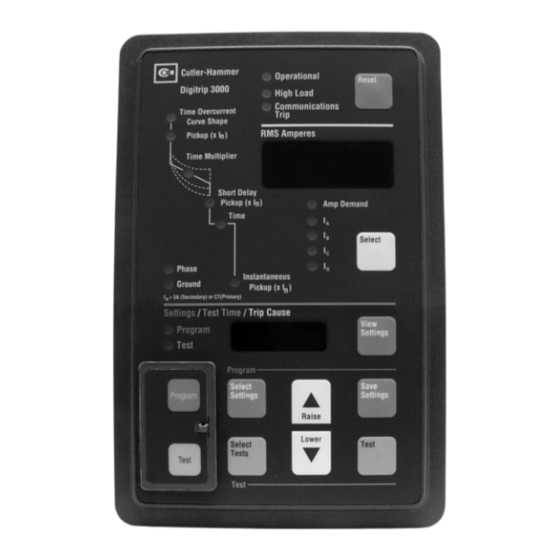
Page 20: Protective Relay Hardware
Instruction Leaflet DT3000 I.B. 17555F Page 14 Effective: Date 02/2006 2-2 PROTECTIVE RELAY HARDWARE these nominal values may not give optimum system protection or coordination. 2-2.1 FRONT OPERATIONS PANEL Test Mode Pushbutton (Yellow) The operations panel, which is normally accessible from Also located behind the sealed hinged access cover is the the outside of the switch gear panel door, provides a Test Mode pushbutton. - Page 21 DT3000 Instruction Leaflet I.B. 17555F Effective: Date 02/2006 Page 15 time. The demand value is the largest 5-minute average time multiplier is being viewed in the unit’s normal measured since the ampere demand was last reset. operating mode, the LED is a constant green. LED: LED’s are used to indicate a number of functions, Short Delay Setting LED operations and/or warnings.
-
Page 22: 2-2.2 Rear Access Panel
Instruction Leaflet DT3000 I.B. 17555F Page 16 Effective: Date 02/2006 This window has a five digit numeric display and shows: Trip Dip Switch OFF Dip Switch ON The present phase or ground currents. Contacts Position Position The largest phase or ground demand currents since TB 12 &... - Page 23 DT3000 Instruction Leaflet I.B. 17555F Effective: Date 02/2006 Page 17 Terminals 11 and 12 are used for ground zone • interlocking, inverse time overcurrent protection and short Switch S8 is used to enable/disable the ability to delay protection. The zone interlocking function is a low download Set Points from the communication level dc signal used to coordinate with “downstream”...
-
Page 24: 2-2.3 External Hardware
Instruction Leaflet DT3000 I.B. 17555F Page 18 Effective: Date 02/2006 Terminals 12 and 13 are a “NO” configurable contact. DIP circuit breaker to trip due to any type of phase fault or Switch S3 is used to configure the trip contacts. With DIP communications. - Page 25 DT3000 Instruction Leaflet I.B. 17555F Effective: Date 02/2006 Page 19 2-3 DT3000 AND DT3030 SPECIFICATIONS AND TEST SUMMARY COMPLIANCE TESTING: OUTPUT TRIP CONTACTS: Certifications: (Trip OC/Comm, Trip Inst, & Comm Close) • • CUL/UL Recognized, File # E154862 Momentary: • CAN/CSA C22.2 No.
-
Page 26: Section 3: Operation
Instruction Leaflet DT3000 I.B. 17555F Page 20 Effective: Date 02/2006 2-3 DT3000 AND DT3030 SPECIFICATIONS AND TEST SUMMARY (CONTINUED) TIME DELAY SETTINGS: ENVIRONMENT: • • Inverse Time Overcurrent Time Multiplier: Environment: It, I t, I t Curve: 0.2 to 40 [48 settings] Indoor Use Only, Pollution Degree II, Altitude 2,500m, Installation Category II Flat: 0.2 to 2.0 [21 settings]... - Page 27 DT3000 Instruction Leaflet I.B. 17555F Effective: Date 02/2006 Page 21 Nominal Continuous Current: The Digitrip 3000’s Moderately Inverse IEC-A nominal continuous primary current (I ) is established Very Inverse IEC-B by the ratio of the selected current transformers. The Extremely Inverse IEC-C current transformer ratio must be set via the initial FLAT...
- Page 28 Instruction Leaflet DT3000 I.B. 17555F Page 22 Effective: Date 02/2006 Short time (fault) protection responds to short circuit current curve that has both inverse time overcurrent and conditions. Similar to the inverse time overcurrent function, short delay protection, and an I t curve shape selected.
- Page 29 DT3000 Instruction Leaflet I.B. 17555F Effective: Date 02/2006 Page 23 Fig. 3-2 Digitrip 3000 Typical Wiring Diagram For more information visit: www.EatonElectrical.com Supersedes I.B. 17555D dated July 2002...
- Page 30 Instruction Leaflet DT3000 I.B. 17555F Page 24 Effective: Date 02/2006 Instantaneous Protection Instantaneous (short circuit) protection reacts to high level Inverse time overcurrent curve shape, pickup, and fault currents. The instantaneous pickup setting time. establishes the current level at which the relay’s Short delay pickup and time.
- Page 31 DT3000 Instruction Leaflet I.B. 17555F Effective: Date 02/2006 Page 25 When “NONE” is selected as a setting, the associated Characteristic Curve Reminders As previously mentioned, combining protective capabilities tripping function is disabled. is a matter of coordination. The effects of one selection When “NONE”...
-
Page 32: 3-3.2 Program Mode
Instruction Leaflet DT3000 I.B. 17555F Page 26 Effective: Date 02/2006 Instantaneous pickup is represented by the dotted portion of the curve. Fig. 3-8 Typical Curve with I T Shape Fig. 3-9 Instantaneous Setting Adjustment When programming is concluded and new set points saved, the Program Mode pushbutton should be 3-3.2 PROGRAM MODE pressed and released to exit the Program Mode. -
Page 33: 3-3.3 Programming Overview
DT3000 Instruction Leaflet I.B. 17555F Effective: Date 02/2006 Page 27 and released to step to the next set point, which is the made and the Select Settings pushbutton is pressed and Phase Time Multiplier. The Time Multiplier setting LED will released, the relay steps to the Phase Ct Ratio Setting. -
Page 34: 3-3.4 Test Mode
Instruction Leaflet DT3000 I.B. 17555F Page 28 Effective: Date 02/2006 the protective access cover. Press and release the Test Mode On/Off pushbutton. The following should be verified before proceeding: Program the Ground The word TEST appears in the alphanumeric display. (First Step) Program the Inverse Time Overcurrent The Test LED is blinking green. -
Page 35: 3-4.1 Address And Baud Rate Settings
DT3000 Instruction Leaflet I.B. 17555F Effective: Date 02/2006 Page 29 provides this capability better than a system with only 3-4.1 ADDRESS AND BAUD RATE SETTINGS selective coordination. To enter the mode that permits changing the device Address and/or BAUD Rate, depress and hold the Test When the “Ground Zone Interlocking”... - Page 36 Instruction Leaflet DT3000 I.B. 17555F Page 30 Effective: Date 02/2006 For ground zone interconnection cable, see cable specifications on Fig. 3-2. Maximum distance between the first and last zone should be 250 feet. Route separate from power conductors. Jumper on devices in last zone used to provide time delay per inverse time overcurrent or short delay time setting. If the jumper is not used the Digitrip 3000 will initiate trip without time delay (nominally 0.1 seconds).
- Page 37 DT3000 Instruction Leaflet I.B. 17555F Effective: Date 02/2006 Page 31 For phase zone interconnection cable, see cable specifications on Fig. 3-2. Maximum distance between the first and last zone should be 250 feet. Route separate from power conductors. Jumper on devices in last zone used to provide time delay per inverse time overcurrent or short delay time setting. If the jumper is not used the Digitrip 3000 will initiate trip without time delay (nominally 0.1 seconds).
-
Page 38: Section 5: Installation, Startup And Testing
Instruction Leaflet DT3000 I.B. 17555F Page 32 Effective: Date 02/2006 Use the 0.38 in. (0.9 cm) long screws included with the relay to mount the unit on a single-thickness panel. SECTION 5: INSTALLATION, STARTUP AND TESTING 5-1 INTRODUCTION Be sure to start the screws from INSIDE the panel, so they This section describes mounting, wiring, startup and go through the metal first. -
Page 39: Wiring
DT3000 Instruction Leaflet I.B. 17555F Effective: Date 02/2006 Page 33 F UNC TION I MPACC Buffers DT3000 DTMV Program with Breaker Open/Cl osed Open Rela y Configuration Phas e/Gnd. OC/I NST Remote open/c lose Ena ble Disable Close Rel ay Config. Hi Load Alm. -
Page 40: 5-5.1 Before Power Application
Instruction Leaflet DT3000 I.B. 17555F Page 34 Effective: Date 02/2006 6-1.1 STORAGE The Digitrip 3000 Protective Relay should be stored in an 5-5.1 BEFORE POWER APPLICATION environment that does not exceed the specified storage Verify that all wiring is correct, as shown on the wiring temperature range of -40°C to +70°C. - Page 41 DT3000 Instruction Leaflet I.B. 17555F Effective: Date 02/2006 Page 35 rear of the relay. Carefully lay the screws aside for later Step 8: Replace each wire at the correct terminal. Be sure use. that each is firmly tightened. Remove temporary shorts on incoming current transformers.
- Page 42 Instruction Leaflet DT3000 I.B. 17555F Page 36 Effective: Date 02/2006 TABLE 6.1 TROUBLESHOOTING GUIDE Symptom Probable Cause Possible Solution(s) Reference Operational LED is • • • Protective Relay’s Control Verify that Control Power is Connected Figure 3-1 Power is Deficient or Between TB1 -5 and B1 -6 and that it is Absent within Specifications...
-
Page 43: Section 7: Time-Current Curves
DT3000 Instruction Leaflet I.B. 17555F Effective: Date 02/2006 Page 37 Much Faster than “Down-Stream” Breaker Expected on Inverse NOTE: During an Internal Test, there is No Time Overcurrent Blocking Signal from a “DownStream” Breaker, (continued) therefore, add jumper for test. Circuit Breaker Trips •... - Page 44 Instruction Leaflet DT3000 I.B. 17555F Page 38 Effective: Date 02/2006 Figure 7-1a Inverse Time Overcurrent Phase, I T Curves (SC-5390-92B) DT 3100 & DT 3101 Users See Figure 7-1b Minimum Pickup 0.2 Maximum Pickup 2.2 10000.00 Adjustable Inverse Time Overcurrent Pickup (x I ) (0.2……….2.2) Adjustable Inverse Time Overcurrent Time...
- Page 45 DT3000 Instruction Leaflet I.B. 17555F Effective: Date 02/2006 Page 39 Figure 7-1b Inverse Time Overcurrent Phase, I T Curves (SC-5390-92B) For DT 3100 & DT 3101 Users ONLY Minimum Pickup 0.2 Maximum Pickup 1.0 10000.00 Adjustable Inverse Time Overcurrent Pickup (x I ) (0.2……….1.0) Adjustable Inverse Time Overcurrent Time...
- Page 46 Instruction Leaflet DT3000 I.B. 17555F Page 40 Effective: Date 02/2006 Figure 7-2a Inverse Time Overcurrent Phase I T Curves (SC-5391-92B) DT 3100 & DT 3101 Users See Figure 7-2b Minimum Pickup 0.2 Maximum Pickup 2.2 10000.00 Adjustable Inverse Time Overcurrent Pickup (x I ) (0.2……….2.2) Adjustable Inverse Time Overcurrent Time...
- Page 47 DT3000 Instruction Leaflet I.B. 17555F Effective: Date 02/2006 Page 41 Figure 7-2b Inverse Time Overcurrent Phase I T Curves (SC-5391-92B) For DT 3100 & DT 3101 Users ONLY Minimum Pickup 0.2 Maximum Pickup 1.0 10000.00 Adjustable Inverse Time Overcurrent Pickup (x I ) (0.2……….1.0) Adjustable Inverse Time Overcurrent Time...
- Page 48 Instruction Leaflet DT3000 I.B. 17555F Page 42 Effective: Date 02/2006 Figure 7-3a Inverse Time Overcurrent Phase, IT Curve (SC-5392-92B) DT 3100 & DT 3101 Users See Figure 7-3b Minimum Pickup 0.2 Maximum Pickup 2.2 1000.00 Adjustable Inverse Time Overcurrent Pickup (x I ) (0.2……….2.2) Adjustable Inverse Time Overcurrent Time...
- Page 49 DT3000 Instruction Leaflet I.B. 17555F Effective: Date 02/2006 Page 43 Figure 7-3b Inverse Time Overcurrent Phase, IT Curve (SC-5392-92B) For DT 3100 & DT 3101 Users ONLY Minimum Pickup 0.2 Maximum Pickup 2.2 1000.00 A d ju s ta b le In ve rs e T im e O ve rc u rr e n t P ic ku p ( x I ) ( 0 .2 …...
- Page 50 Instruction Leaflet DT3000 I.B. 17555F Page 44 Effective: Date 02/2006 Figure 7-4a Inverse Time Overcurrent Phase, Flat Curves (SC-5393-92B) DT 3100 & DT 3101 Users See Figure 7-4b Minimum Pickup 0.2 Maximum Pickup 2.2 1000.00 Adjustable Inverse Time Overcurrent Pickup (x I ) (0.2……….2.2) Adjustable Inverse Time Overcurrent Time Multiplier...
- Page 51 DT3000 Instruction Leaflet I.B. 17555F Effective: Date 02/2006 Page 45 Figure 7-4b Inverse Time Overcurrent Phase, Flat Curves (SC-5393-92B) For DT 3100 & DT 3101 Users Only Minimum Pickup 0.2 Maximum Pickup 1.0 1000.00 Adjustable Inverse Time Overcurrent Pickup (x I ) (0.2……….1.0) Adjustable Inverse Time Overcurrent Time Multiplier (0.2 s……….2 s)
- Page 52 Instruction Leaflet DT3000 I.B. 17555F Page 46 Effective: Date 02/2006 Figure 7-5 Short Delay Phase Curves (SC-5394-92B) 10000.00 Adjustable Short Delay Settings (x I ) (1.0……….11, None) Adjustable Short Delay Time (0.05 s……….1.5 s) Tolerance: Short Delay Setting is ±10% Short Delay Time is ±50 ms and –50 ms Short Delay uses the O/C Contact 1000.00...
- Page 53 DT3000 Instruction Leaflet I.B. 17555F Effective: Date 02/2006 Page 47 Figure 7-6 Inverse Time Overcurrent/Short Delay Curves (SC-5395-92B) 10000.00 Inverse Time Overcurrent Pickup = 1.0 x Inverse Time Overcurrent Time Multiplier = 10 s @ 3 x I Short Delay Setting = 11 x Short Time Delay = 1.5 s Note: The Short Delay Time is used as the shortest tip time possible in Inverse Time Overcurrent or Short Delay...
- Page 54 Instruction Leaflet DT3000 I.B. 17555F Page 48 Effective: Date 02/2006 Figure 7-7 Instantaneous Curves (SC-5396-92B) 10000.00 Adjustable Instantaneous Trip (Phase Element) (1……….25 x I None) Adjustable Instantaneous Trip (Ground Element) (0.5……….11 x I None) Tolerance: Instantaneous Setting is ±10% Instantaneous uses the Instantaneous Contact 1000.00 100.00 Ground, Lowest Setting...
- Page 55 DT3000 Instruction Leaflet I.B. 17555F Effective: Date 02/2006 Page 49 Figure 7-8 Inverse Time Overcurrent Ground I T Curve (SC-5399-92B) Minimum Pickup 0.1 Maximum Pickup 2.0 10000.00 Adjustable Inverse Time Overcurrent Ground Pickup (x I ) (0.1……….2.0 None) Adjustable Inverse Time Overcurrent Time Multiplier Ground (Sec.
- Page 56 Instruction Leaflet DT3000 I.B. 17555F Page 50 Effective: Date 02/2006 Figure 7-9 Inverse Time Overcurrent Ground I T Curve (SC-5400-92B) Minimum Pickup 0.1 Maximum Pickup 2.0 10000.00 Adjustable Inverse Time Overcurrent Pickup (x I ) (0.1……….2.0 None) Adjustable Inverse Time Overcurrent Time Multiplier Ground (Sec.
- Page 57 DT3000 Instruction Leaflet I.B. 17555F Effective: Date 02/2006 Page 51 Figure 7-10 Inverse Time Overcurrent Ground IT Curve (SC-5401-92B) Minimum Pickup 0.1 Maximum Pickup 2.0 1000.00 Adjustable Inverse Time Overcurrent Pickup (x I ) (0.1……….2.0 None) Adjustable Inverse Time Overcurrent Time Multiplier Ground (Sec.
- Page 58 Instruction Leaflet DT3000 I.B. 17555F Page 52 Effective: Date 02/2006 Figure 7-11 Inverse Time Overcurrent Ground, Flat Curves (SC-5402-92B) 1000.00 Adjustable Inverse Time Overcurrent Ground Pickup (x I ) (0.1……….2.0 None) Adjustable Inverse Time Overcurrent Time Multiplier Ground (0.2 s……….2 s) Tolerance: Inverse Time Overcurrent Pickup is ±5% Inverse Time Overcurrent Time Multiplier is +50ms or –50ms 100.00...
- Page 59 DT3000 Instruction Leaflet I.B. 17555F Effective: Date 02/2006 Page 53 Figure 7-12 Short Delay Ground Curves (SC-5403-92B) 1000.00 Adjustable Short Delay Ground Settings (x I ) (0.1……….11, None) Adjustable Short Delay Time Ground (0.5 s……….1.5 s) Tolerance: Short Delay Setting is ±10% Short Delay Time is +50ms or –50ms Short Delay uses the O/C Contact 100.00...
- Page 60 Instruction Leaflet DT3000 I.B. 17555F Page 54 Effective: Date 02/2006 Figure 7-13 ANSI Moderately Inverse Curves (SC-6685-96) 1000.00 Adjustable Time Multiplier (0.1………5.0) Tolerance: Time Multiplier Tolerance is ± 10% or ± 0.09s, whichever is larger (>1.5 x I For Ground Pickup <0.2 : trip time tolerance is ±15% 100.00 10.00...
- Page 61 DT3000 Instruction Leaflet I.B. 17555F Effective: Date 02/2006 Page 55 Figure 7-14 ANSI Very Inverse Curves (SC-6686-96) 1000.00 Adjust able Time Mult iplier (0.1………5.0) Tolerance: Time Mult iplier Tolerance is ± 10% or ± 0.09 s, w hichever is larger (> 1.5 x I For Ground Pickup <...
- Page 62 Instruction Leaflet DT3000 I.B. 17555F Page 56 Effective: Date 02/2006 Figure 7-15 ANSI Extremely Inverse Curves (SC-6687-96) 1000.00 Adjustable Time Multiplier (0.1………5.0) Tolerance: Time Multiplier Tolerance is ± 10% or ± 0.09 s, w hichever is larger (> 1.5 x I For Ground Pickup <...
- Page 63 DT3000 Instruction Leaflet I.B. 17555F Effective: Date 02/2006 Page 57 Figure 7-16 IEC-A Moderately Inverse Curves (SC-6688-96) 1000.00 Adjustable Time Multiplier (0.05………1.00) Tolerance: Time Multiplier Tolerance is ± 10% or ± 0.09 s, whichever is larger (>1.5 x I For Ground Pickup <0.2 : trip time tolerance is ±15% 100.00 10.00...
- Page 64 Instruction Leaflet DT3000 I.B. 17555F Page 58 Effective: Date 02/2006 Figure 7-17 IEC-B Very Inverse Curves (SC-6689-96) 1000.00 Adjustable Time Multiplier (0.05………1.00) Tolerance: Time Multiplier Tolerance is ± 10% or ± 0.09 s, whichever is larger (>1.5 x I For Ground Pickup <0.2 : trip time tolerance is ±15% Minimum Trip Time is 2 power line cycles 100.00...
- Page 65 DT3000 Instruction Leaflet I.B. 17555F Effective: Date 02/2006 Page 59 Figure 7-18 IEC-C Extremely Inverse Curves (SC-6690-96) 1000.00 Adjustable Time Multiplier (0.05………1.00) Tolerance: Time Multiplier Tolerance is ± 10% or ± 0.09 s, whichever is larger (>1.5 x I For Ground Pickup <0.2 : trip time tolerance is ±15% Minimum Trip Time is 2 power line cycles 100.00...
- Page 66 Instruction Leaflet DT3000 I.B. 17555F Page 60 Effective: Date 02/2006 Figure 7-19 IEC-D Family Flat (SC-6691-96) 1000.00 Adjustable Time Multiplier (0.05………1.00) Tolerance: Time Multiplier Tolerance is ± 0.05 s, 100.00 10.00 Time Multiplier 1.00 0.15 0.05 0.10 0.01 Multiple of Pickup Current (I/I For more information visit: www.EatonElectrical.com Supersedes I.B.
-
Page 67: Digitrip 3000 Curve Equations
DT3000 Instruction Leaflet I.B. 17555F Effective: Date 02/2006 Page 61 7-2 DIGITRIP 3000 CURVE EQUATIONS Thermal Curve Equation SLOPE T = Trip Time D * K D = Time Multiplier (0.2 to 40) IT 1 I = Input Current I2T 2 M = Slope (0 = FLAT, 1 = IT, 2 = I2T, 4 = 14T) I4T 4 K = 3 for phase, 1 for ground FLAT 0 FLAT... -
Page 68: A1.0 Introduction
Instruction Leaflet DT3000 I.B. 17555F Page 62 Effective: Date 02/2006 APPENDIX A A1.0 INTRODUCTION Appendix A describes the Drawout Case option for the Digitrip 3000 Protective Relay. The table below (A-1) lists the Drawout Case versions. Table A-1 Ordering Information NEW Style # OLD Style # Catalog #... -
Page 69: A4.0 Wiring And Setup
DT3000 Instruction Leaflet I.B. 17555F Effective: Date 02/2006 Page 63 A4.0 WIRING AND SETUP NOTE: The Protection Off Alarm Relay is energized when control power is applied and the DT3001 is operating properly. To obtain a contact that closes when protection is lost, use terminals 48 & 50. For a contact that opens when protection is lost, use ENSURE THAT THE INCOMING AC POWER terminals 46 &... - Page 70 Instruction Leaflet DT3000 I.B. 17555F Page 64 Effective: Date 02/2006 FUNCTION IMPACC Buffers DT3000 DTMV Program with Breaker Open/Closed Open Relay Configuration Phase/Gnd. OC/INST Remote open/close Enable Disable Close Relay Config. Hi Load Alm. Comm. Close Zone Interlocking Latched Unlatched Breaker Input Mode Download Setpoints Enable...
- Page 71 DT3000 Instruction Leaflet I.B. 17555F Effective: Date 02/2006 Page 65 FIG. A-4 DIGITRIP 3001 TYPICAL AC OR DC SCHEMATIC FIG. A-5 DIGITRIP 3001 TYPICAL AC EXTERNAL FIG. A-6 DIGITRIP 3001 TYPICAL RESIDUAL GROUND CURRENT CONNECTION WITH ZERO SEQUENCE CONNECTION GROUND CT For more information visit: www.EatonElectrical.com Supersedes I.B.
- Page 72 Instruction Leaflet DT3000 I.B. 17555F Page 66 Effective: Date 02/2006 Fig. A-7 Digitrip 3001 Typical Wiring Diagram For more information visit: www.EatonElectrical.com Supersedes I.B. 17555D dated July 2002...
-
Page 73: A5.0 Application Considerations
DT3000 Instruction Leaflet I.B. 17555F Effective: Date 02/2006 Page 67 A5.0 APPLICATION CONSIDERATIONS Zone selective interlocking is available on the Digitrip 3001 Protective Relays for the inverse time and short time functions on the phase and ground elements. Refer to Figure A-8 for a typical phase zone selection interlocking wiring diagram or Figure A-9 for a typical ground zone interlocking wiring diagram. -
Page 74: A6.2 Removing The Relay
Instruction Leaflet DT3000 I.B. 17555F Page 68 Effective: Date 02/2006 compressed position. The device can now be secured in When removing the Inner Chassis from the Drawout Outer the enclosure by inserting a utility locking ring in the Case, first remove any locking ring that has been installed. provided slot. -
Page 75: B1.0 Introduction
DT3000 Instruction Leaflet I.B. 17555F Effective: Date 02/2006 Page 69 model) auxiliary power, which is normally connected and available. APPENDIX B B1.0 INTRODUCTION • Operates solely from the main current transformers This appendix describes the Dual-Source Power Supply (Ct) during a fault if the normally connected auxiliary (DSPS) addition to the Digitrip 3000 Protective Relay. - Page 76 Instruction Leaflet DT3000 I.B. 17555F Page 70 Effective: Date 02/2006 Table B-2 DT3010 AND DT3020 SPECIFICATIONS AND TEST SUMMARY COMPLIANCE TESTING: OUTPUT TRIP CONTACTS: Certifications: (Trip OC/Comm, Trip Inst, & Comm Close) • • CUL/UL Recognized, File # E154862 Momentary: •...
-
Page 77: B3.0 Functional Description
DT3000 Instruction Leaflet I.B. 17555F Effective: Date 02/2006 Page 71 Table B-2 DT3010 AND DT3020 SPECIFICATIONS AND TEST SUMMARY (CONTINUED) TIME DELAY SETTINGS: ENVIRONMENT: • • Inverse Time Overcurrent Time Multiplier: Environment: It, I t, I t Curve: 0.2 to 40 [48 settings] Indoor Use Only, Pollution Degree II, Altitude 2,500m, Flat: 0.2 to 2.0 [21 settings] Installation Category II... - Page 78 Instruction Leaflet DT3000 I.B. 17555F Page 72 Effective: Date 02/2006 Fig. B-2 Digitrip 3010/3020 Dimensions (Inches) For more information visit: www.EatonElectrical.com Supersedes I.B. 17555D dated July 2002...
-
Page 79: B5.0 Wiring And Setup
DT3000 Instruction Leaflet I.B. 17555F Effective: Date 02/2006 Page 73 B5.0 WIRING AND SETUP WARNING BEWARE OF MISAPPLICATION OF MAIN-CT ENSURE THAT THE INCOMING AC POWER RATIOS. CONSIDER A CIRCUIT WITH A 400A SOURCES ARE DISCONNECTED BEFORE LOAD THAT NORMALLY REQUIRES A 400:5 CT PERFORMING ANY WORK ON THE DIGITRIP 3000 RATIO, BUT THE CT IS CONNECTED FOR 1200:5. - Page 80 Instruction Leaflet DT3000 I.B. 17555F Page 74 Effective: Date 02/2006 Fig. B-3 Digitrip 3010/3020 Protective Relay Typical AC Schematic FIG. B-4 DIGITRIP 3010/3020 TYPICAL AC FIG. B-5 DIGITRIP 3010/3020 TYPICAL RESIDUAL EXTERNAL CURRENT CONNECTION WITH ZERO GROUND CONNECTION SEQUENCE GROUND CT For more information visit: www.EatonElectrical.com Supersedes I.B.
-
Page 81: B6.4 Burden Data
DT3000 Instruction Leaflet I.B. 17555F Effective: Date 02/2006 Page 75 The Digitrip 3000 is a true rms measuring device, and will integrate the spikes and dead periods to arrive at a current B7.1 IN-SERVICE TEST measurement. The user should follow standard application guidelines of comparing the Ct saturation curve with the total connected burden, in light of the maximum fault current. - Page 82 Instruction Leaflet DT3000 I.B. 17555F Page 76 Effective: Date 02/2006 test. Check the value against the “No Vac, 1 Phase I” “With Vac, 1 Phase I” curve of Figure B-8. With ac curve, the highest curve, of Figure B-8. power applied, this voltage will be roughly half of the Apply ac control voltage again, with Phase C current value without the ac power applied.
- Page 83 DT3000 Instruction Leaflet I.B. 17555F Effective: Date 02/2006 Page 77 Ct Power in VA, with Vac, 3 Phase I Ct Power in VA, No Δ Vac, 3 Phase I Ct Power in VA, ο with Vac, 1 Phase I Ct Power in VA, No Vac, 1 Phase I Fig.
- Page 84 Instruction Leaflet DT3000 I.B. 17555F Page 78 Effective: Date 02/2006 DSPS Output - True 3 Phase Current Only DSPS Output - 1 Phase Current Only Fig. B-9 DSPS Output Voltage to Relay For more information visit: www.EatonElectrical.com Supersedes I.B. 17555D dated July 2002...
- Page 85 MERCHANTABILITY, OR WARRANTIES ARISING FROM COURSE OF DEALING OR USAGE OF TRADE, ARE MADE REGARDING THE INFORMATION, RECOMMENDATIONS AND DESCRIPTIONS CONTAINED HEREIN. Eaton Corporation Cutler-Hammer business unit 1000 Cherrington Parkway Moon Township, PA 15108-4312 I.B. 17555F / Style # 8163A25H07 for technical support: www.EatonElectrical.com...
Need help?
Do you have a question about the Cutler-Hammer DIGITRIP 3000 Series and is the answer not in the manual?
Questions and answers