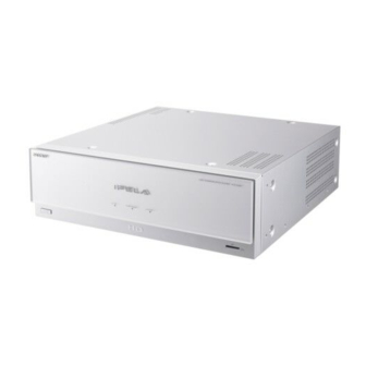
Sony IPELA PCS-HG90 Operating Instructions Manual
High definition 1080i visual codec
Hide thumbs
Also See for IPELA PCS-HG90:
- Connection setup (2 pages) ,
- Brochure & specs (6 pages) ,
- Specification sheet (2 pages)

Related Manuals for Sony IPELA PCS-HG90


Summary of Contents for Sony IPELA PCS-HG90
- Page 1 3-991-626-15 (1) Video Communication System Operating Instructions (Version 2.2) Before operating the unit, please read this manual thoroughly and retain it for future reference. PCS-HG90 © 2006 Sony Corporation...
- Page 2 Installing batteries in the space provided below. Refer to these Two R6 (size AA) batteries are supplied for numbers whenever you call upon your Sony Remote Commander. dealer regarding this product. To avoid risk of explosion, use R6 (size AA) manganese or alkaline batteries.
- Page 3 In the case that interference should occur, consult your nearest authorized Sony service facility. Voor de Klanten in Nederland Gooi de batterij niet weg maar lever deze in als klein chemisch afval (KCA).
-
Page 4: Table Of Contents
Table of Contents Chapter 1: Installation and Preparation Using This Manual ....................9 Features ........................10 System Components ....................11 Basic System Components ................11 Optional Equipment ..................12 System Configuration .................... 14 System Configuration for Peer-to-Peer Connection ........14 System Configuration for Multipoint Connection ........... - Page 5 Status Menu ...................... 39 Audio Setup Menu .................... 41 Video Setup Menu .................... 43 General Setup Menu ..................47 Administrator Setup Menu ................50 LAN Setup Menu ..................... 54 Encryption Setup Menu ..................59 Machine Information Menu ................59 Registering a Remote Party – Phone Book ............60 Registering a New Remote Party in the Phone Book ........
- Page 6 Adjusting the Focus and Brightness ..............98 Presetting the Angle and Zoom Settings ............99 Recalling the Preset Angle and Zoom Setting ..........101 Selecting the Input Picture and Sound ..............103 Switching the Displayed Picture Between the Local and Remote Pictures ... 103 Selecting the Input Picture ................
- Page 7 What is “Broadcast Mode”? ................141 Switching the Broadcast Mode ............... 141 Receiving the Broadcast Requested From Any Other Terminal ....142 Ending the Multipoint Connection ............... 143 Chapter 7: Web Control Function Open the Web page ....................144 Identify a user ....................... 145 Select a tool ......................
- Page 8 PCSA-A3 Microphone (Optional) ..............180 PCSA-A7P4 Microphone (4-pack, optional) ..........180 Acceptable RGB Input/Output Signals ............181 Pin Assignments ..................... 182 List of Port Numbers Used on the PCS-HG90 ..........184 Video Communication Room Layout ..............185 Camera Range ....................185 “Memory Stick”...
-
Page 9: Chapter 1: Installation And Preparation
Chapter 5: Encrypted Connection Chapter 1: This chapter describes how to connect with encrypted video and audio. Installation and Chapter 6: Multipoint Connection This chapter shows you how to connect at Preparation the multipoint. Chapter 7: Web Control Function This chapter shows you how to control the PCS-HG90 or set it up via a Web browser. -
Page 10: Features
YPbPr (component signal) connectors for video input/output, allowing shooting, transmission and reception of digital signal. It is also equipped with XLR- type audio input/output connectors, enabling connection with audio equipment for professional use. “IPELA” and are trademarks of Sony Corporation. Features... -
Page 11: System Components
System Components The PCS-HG90 Video Communication System is composed of basic system components for a basic connection, and optional equipment for an enhanced communication. Basic System Components The PCS-PHG90 Communication Terminal is the basic system of the PCS-HG90 Video Communication System. It contains the following components: Unit Description... -
Page 12: Optional Equipment
Optional Equipment TV monitor A TV or projector, etc. is required to monitor the images. Unit Description TV, Projector, etc. Used as a monitor and speakers. Optional equipment especially designed for use with the PCS-HG90 The following optional devices are used to perform your video communication. - Page 13 Unit Description PCSA-A7P4 Echo Canceling Narrow coverage monaural microphones that feature Microphone high sound quality and a built-in echo canceler. Several PCSA-A7 microphones can be connected in cascade, without losing sound quality. Recommended when using several microphones. (4-piece set) System Components...
-
Page 14: System Configuration
System Configuration The PCS-HG90 Video Communication System has various system configuration capabilities using the basic components and optional equipment. This section describes the capabilities and necessary equipment for some typical configuration examples. System Configuration for Peer-to-Peer Connection This allows you to: •... -
Page 15: System Configuration For Multipoint Connection
System Configuration for Multipoint Connection This allows you to: • Hold a multipoint connection among up to four sites over LAN. System configuration ON LINE POWER/STANDBY LAN ALERT ON LINE POWER/STANDBY LAN ALERT ON LINE POWER/STANDBY LAN ALERT ON LINE POWER/STANDBY LAN ALERT 1 PCS-PHG90 Communication Terminal... -
Page 16: System Configuration Using The Pcsa-A7 Echo Canceling Microphones
System Configuration Using the PCSA-A7 Echo Canceling Microphones This allows you to: • Connect up to 40 PCSA-A7 Echo Canceling Microphones to one microphone connector, using a cascade connection. PCSA-A7 Microphones can be connected in cascade, without a decrease in sound quality, ideal for large meetings. -
Page 17: System Connections
System Connections This section describes the typical system connections. Caution • Be sure to turn off all the equipment before making any connections. • Do not connect/disconnect the BNC cable or VISCA cable with the power on. Doing so may damage the Camera Unit or Communication Terminal. •... - Page 18 PCSA-CHG90 Camera Unit VISCA RS-422 to AC outlet 1 2 3 4 5 6 7 8 9 DC IN 12V VISCA RS-232C OUT MONITOR HD-SDI HFBK-HD1 to HD-SDI to VISCA RS-232C IN BNC cable*(supplied Power cord with the Camera Unit) (supplied) VISCA cable (supplied with to a wall outlet...
- Page 19 To set the BOTTOM switch of the PCSA-CHG90 Camera Unit When you set the Frequency of Video Format to “50 Hz”, set the BOTTOM switch (59.94i/50i signal format selector) on the bottom of the Camera Unit to “ON” (HD video format of 50i system). For details on the Frequency of Video Format, See page 44.
- Page 20 Connection using the VISCA RS-422 When you use the VISCA RS-422 connector on the Camera Unit to make the remote control connection with the Communication Terminal instead of the VISCA RS-232C connector, use of a converter between RS-422 and RS-232C is required.
-
Page 21: Preparing The System
Preparing the System Attaching the Remote Control Receiver Most operations with the Video Communication System can be controlled with the supplied Remote Commander. To use the Remote Commander, point it to the supplied remote control receiver. Connect the remote control receiver to the CTRL-S jack on the Communication Terminal. -
Page 22: Inserting Batteries Into The Remote Commander
To attach the filter to the remote control receiver Peel off the paper from the rear of the supplied filter and paste the filter over the remote sensor of the remote control receiver. Filter (supplied) Remote sensor Inserting Batteries into the Remote Commander Most of the operations with the Video Communication System can be controlled with the supplied Remote Commander. - Page 23 Replace the cover. Battery life When the Remote Commander does not function properly, replace both the batteries with new ones. Notes on batteries To avoid damage from possible battery leakage or corrosion, observe the following: • Make sure to insert the batteries with the polarities in the correct direction. •...
-
Page 24: Turning The System On/Off
Turning the System On/Off This section describes how to turn on or off the Communication Terminal. Turning On Turn on the TV monitor. Turn on the power of any other equipment to be used. Press the (power) switch on the Communication Terminal to turn it on. (Power) switch POWER indicator POWER/STANDBY indicator... - Page 25 Notes • If you use force to prevent the camera moving, it may not resume moving and not output a signal to the Communication Terminal. In this case, turn off the terminal, and turn it on again. • When you turn on the power of the Communication Terminal for the first time after installation, the setup wizard will appear after the self-diagnosis is completed.
-
Page 26: Standby Mode Function
Standby Mode Function To save power, the Communication Terminal can enter standby mode if you do not operate it for a specified period of time. When the Communication Terminal is in standby mode, the STANDBY indicator on the Camera Unit and the POWER/STANDBY indicator on the Communication Terminal light in orange. -
Page 27: Turning Off
To cancel setting the system to standby Select “Cancel” with the B or b button on the Remote Commander, then press the PUSH ENTER button in step 2 above. To release the standby mode Press any button on the Remote Commander. To specify the standby time Specify the time that you want the system to remain on before entering into standby mode (max. -
Page 28: Displaying Help
Adjust the volume on the TV monitor so that you can properly hear a remote party speaking. Note Do not activate the TV’s surround sound feature as it may cause the echo canceler of the Communication Terminal not to function properly and make strange sounds. Displaying Help Pressing the HELP button on the Remote Commander displays help to guide most operations in the guidance area. -
Page 29: Setting Up The System For The First Time - Initial Setup Wizard
Auto: Automatically assigns your IP Setting Up the address, network mask, gateway address and DNS address. System for the First Off: Deactivates DHCP. In this case set Time — Initial Setup your IP address, network mask, gateway address and DNS address Wizard manually. -
Page 30: Using The Menus
PUSH ENTER button. Using the Menus The selected setup menu appears. 2005.12.28 12:34 General Setup The Video Communication System uses the Menu Screens Page: on-screen menus to make various adjustments Time Display and settings. This section describes how to Show temporarily Display Terminal Name Character Input Help adjust or set the items in the menus and gives... - Page 31 To return to the previous menu Press the RETURN button on the Remote Commander. Using the Menus...
-
Page 32: Menu Configuration
Menu Configuration The system menus are configured as outlined below. For details about menu configuration, see “Menu Configuration” on page 190. Launcher menu Setup menu Setup menus 2005.12.28 12:34 2005.12.28 12:34 2005.12.28 12:34 Menu Setup Dial Setup Page: Back Phone Book Dial Answer Room 10A... - Page 33 Launcher menu Detailed Dial menu 2005.12.28 12:34 2005.12.28 12:34 Detailed Dial Menu Phone Book Room 10A Detailed Dial History Dial Mode Single Room 11B Room 01 IP:255.255.255.255 Capture Communication Bit Rate 2 Mbps More options Dial Save Cancel Dial Room 12A Enter the remote party number.
-
Page 34: Entering Characters
Camera menu Entering Characters 2005.12.28 12:34 Camera This section explains how to enter the Preset Save Back letters, numbers or symbols on the text box Camera Preset Load Memory Stick Adjustments in the menu using the Remote Commander. Setup Auto Track Stop Video: HD-SD 1 ON/OFF VOLUME... - Page 35 To enter a symbol Press the VIDEO INPUT (SYMBOL) button repeatedly to select the desired symbol. Pressing the 0 button repeatedly also enables you to enter a symbol. To enter a dot (.) for an IP address Press the button. To delete a character Press the PinP (BACK SPACE) button.
-
Page 36: Chapter 2: Registration And Setup For System Administrators
Menus available in the Setup Chapter 2: menu Selecting the following items opens their respective menus. Registration and Dial: Dial Setup menu (see page 37) Answer: Answer menu (see page 37) Setup for System Communication: Communication Mode menu (see page 38) Status: Status menu (see page 39) Administrators Audio: Audio Setup menu... -
Page 37: Dial Setup Menu
To cancel the setup Select LAN Prefix V, v, B or b Use the button on the Remote Allows you to select whether to use the LAN Commander to select “Cancel”, then press prefix. the PUSH ENTER button. Or press the Enable: Enable the LAN prefix. -
Page 38: Communication Mode Menu
Page 2/2 Communication Mode Menu Note The Communication Mode menu is used to The following example shows the display set up communications. when “Peer-to-Peer/Multipoint” and “Transmission/Reception Bit Rate” are set to Page 1/2 “Common Settings” on page 1/2. When they are set to “Individual Settings”, individual Note setting items are displayed. -
Page 39: Status Menu
When “Peer-to-Peer/Multipoint” on page AAC Stereo 96K: Sends or receives audio 1/2 is set to “Individual Settings”, you can based on the MPEG4 AAC stereo format configure Peer-to-Peer and Multipoint (96K). individually. G.728: Sends or receives audio based on the G.728 standard. - Page 40 The items below are shown both in the LAN Connection Status columns for “Encode” and “Decode”. The descriptions under “Encode” show the 2005.12.28 12:34 trasmission status of the local system and those Status LAN Status (communication in progress) under “Decode” show the status of the Page: Connection A Encode...
-
Page 41: Audio Setup Menu
MIC+AUX: Inputs audio from the Input/Output/Peripheral Status microphones and auxiliary external equipment. 2005.12.28 12:34 Status Input/Output/Peripheral Status AUDIO IN Page: Allows you to select the microphone to be Video Input VIDEO IN Audio Input AUDIO IN used and the audio input from auxiliary VIDEO OUT Video Output external equipment. - Page 42 Page 2/4 Page 3/4 2005.12.28 12:34 2005.12.28 12:34 Audio Setup Audio Setup Page: Page: Echo Canceler HD-SDI 1 Input Channel CH1/2 Audio Output Delay Setting Default HD-SDI 2 Input Channel CH1/2 Audio Output Delay HD-SDI Output Channel Recording Mute Reversed MIC Inputs AUX Local Monitor Out REC OUT Mode Stereo...
-
Page 43: Video Setup Menu
AUX Local Monitor Out Video Setup Menu Allows you to select whether to output the audio which is input from the AUDIO IN The following menus appear when you AUX 1 or the AUX 2 connectors from the select “Video” on the Setup menu. Select the audio output of the communication terminal. - Page 44 RGB: Selects the picture from external Video Format equipment connected to the VIDEO IN RGB connectors. 2005.12.28 12:34 S-VIDEO: Selects the picture from external Video Srtup Video Format equipment connected to the VIDEO IN Page: S-VIDEO connector. Output Video Format 1080 Frequency 60Hz...
- Page 45 Page 4/5: RGB Note Page 5/5: S-VIDEO When you change the “Video Format,” the system will reboot automatically. For details on the setting, see “Setting the Transmitting Image Quality” on page 74. Custom Input Label Setting Mode Allows you to set the names displayed in the Select whether all items are set Video Input/Output menu.
- Page 46 Bandwidth Limiting: Encoder frame rate Default Display Pattern control is performed, giving priority to Allows you to select the display pattern of the transmission within the specified the images on your monitor screen. The bandwidth. selected pattern appears when communication is next established. The pattern can be switched by using the Other Settings (Page 1/2) buttons on the Remote Commander during...
-
Page 47: General Setup Menu
Aspect Ratio for S-VIDEO Input Off: The message above does not appear and remote party registration does not take Allows you to select the aspect ratio for S- place. VIDEO video input signal: “4:3” or “16:9”. Control by Far End When “Far End Camera Control”... - Page 48 Secondary NTP Server Always on: Displays the terminal names. Allows you to input the address of the Character Input Help Secondary NTP Server that gets the time Allows you to select whether to display help information. text in the guide area when entering Time Zone characters and numbers.
- Page 49 Launcher Screen (Page 1/3) Launcher Screen (Page 2/3) Allows you to select whether to display Allows you to select whether to display menus and buttons of the launcher screen. menus and buttons of the launcher screen. 2005.12.28 12:34 2005.12.28 12:34 General Setup General Setup Launcher Screen...
-
Page 50: Administrator Setup Menu
GK:User Alias: Displays the user name 2005.12.28 12:34 registered in the gatekeeper when you Administrator Setup Password use the gatekeeper. Page: GK:User Number: Displays the user Administrator Password Phone Book Modification Password number registered in the gatekeeper Save Settings Password when you use the gatekeeper. - Page 51 Disable: No need for the password when Encryption Setup saving the Dial Setup settings. Enable: No need for the pass word when saving the Encryption Setup settings. Answer Setup Disable: Need for the password when Enable: Need for the password when saving saving the Encryption Setup settings.
- Page 52 Auto Dialing Saves the data for each setting to a “Memory Stick”. The data for each setting saved on the Allows you to automatically contact the “Memory Stick” is overwritten. remote parties of the selected Private Phone Book on a “Memory Stick” when you insert Note it into the system.
- Page 53 For details on the measurement, see The load and stress test is possible only when “Measuring the Network Quality” on page the remote terminal is PCS-HG90 with version 2.2 or later. 2005.12.28 12:34 Start Measurement Administrator Setup Network Quality Measurement Select this button to start the network quality Page: measurement.
-
Page 54: Lan Setup Menu
LAN Setup Menu 2005.12.28 12:34 Administrator Setup Resout of Network Quality Measurement Simplex The following menus appear when you Page: Network Quality Status select “LAN” on the Setup menu. Select the Packet Loss (%) Jitter (ms) Packet Loss (%) Jitter (ms) Encode Decode Encode Decode Encode Decode... - Page 55 Enter the default gateway address. Gatekeeper Address Enter the address of the gatekeeper used DNS Address when “Gatekeeper Mode” is set to “On”. Enter the DNS (Domain Name System) User Alias address. Enter the user name (H.323 alias) registered General (Page 2/2) in the gatekeeper.
- Page 56 Fixed IP Address for PPPoE PPPoE (Page 1/2) Enter an IP address when “Fixed IP for PPPoE” is set to “On”. 2005.12.28 12:34 LAN Setup PPPoE PPPoE DNS Page: PPPoE Allows you to select whether to obtain DNS PPPoE User Name PPPoE Password server addresses automatically or to specify them manually when connecting to a LAN...
- Page 57 NAT/Port (Page 2/2) 2005.12.28 12:34 LAN Setup Page: 2005.12.28 12:34 Detailed Setup LAN Setup NAT/Port Forward Error Correction(FEC) Page: Packed Resend Request(ARQ) Port Number Used Default Adaptive Rate Control(ARC) TCP Port Number 2253-2263 Auto Bandwidth Detection UDP Port Number 49152-49197 Save Cancel Auto Bandwidth Detection TCP Port Number...
- Page 58 Auto Bandwidth Detection TOS (Page 1/3-3/3) Switches On and Off of the auto bandwidth detection function. 2005.12.28 12:34 On: Uses the automatic bandwidth detection LAN Setup TOS (Video) function. Page: Off: Does not use the automatic bandwidth IP Precedence detection function. Low Delay High Throughput High Reliability...
-
Page 59: Encryption Setup Menu
Allows you to select whether to enable the Connect priority: Connects by encryption High Reliability bit rate of the TOS field. with the party who can be connected by On: Enables the High Reliability bit rate of the standard encryption. Connects the TOS field. -
Page 60: Registering A Remote Party - Phone Book
Registering a 2005.12.28 12:34 List Edit Remote Party – Phone Book Dial Mode Index Single Communication Bit Rate 2 Mbps More Options Save Cancel You can register the IP address of a remote party in the Phone Book or Direct Phone Book, allowing you to dial the party very Enter the name of a remote party in the easily. -
Page 61: Changing The Contents Of The Phone Book
2 Select a Communication Bit Rate To set up more detailed options to be used. 2005.12.28 12:34 Select the captured icon or a still List Edit image to be registered in the Phone Book. Dial Mode Index Room 10A Single Communication Bit Rate 2 Mbps More Options... -
Page 62: Copying The Registered Remote Party
Use the V, v, B or b button on the Use the V, v, B or b button on the Remote Commander to select “Save”, Remote Commander to select “OK”, then press the PUSH ENTER button. then press the PUSH ENTER button. The correction is completed. -
Page 63: Creating A Private Phone Book
same procedure as that with the Phone Book. 2005.12.28 12:34 Administrator Setup Phone Book Page: Note Auto Dial Create Private Phone Book You cannot check, modify or copy the Delete Private Phone Book Direct Phone Book by using the Web Copy to Private Phone Book function. - Page 64 Use the V, v, B or b button on the To delete the Private Phone Book Remote Commander to select “Save”, from the “Memory Stick” then press the PUSH ENTER button. Insert the “Memory Stick” from which you The setting is registered and “AUTO” want to delete the registered Private Phone appears on the registered list.
-
Page 65: Setting Up The Network Configurations
Setting Up the Network Configurations This section describes how to set up the network configurations for use with various networks. For details on the LAN Setup menu, see “LAN Setup Menu” (page 54). For details on configurations, consult with the system administrator. LAN (Connecting via DHCP) Configuration example LAN2... -
Page 66: Lan (Connecting Through A Router)
Enter a name in “Host Name” under Page 1/2 of the General screen in the LAN Setup menu, and enter the appropriate values for “IP Address”, “Network Mask”, and “Gateway Address”. 2005.12.28 12:34 LAN Setup General Page: DHCP Mode Host Name Sony IP Address 192.100.10.10 225.225.225.0 Network Mask Gateway Address 192.100.10.1 DNS Address Save... -
Page 67: Lan (Connecting Through A Gatekeeper)
Enter a name in “Host Name” under Page 1/2 of the General screen in the LAN Setup menu, and enter the appropriate values for “IP Address”, “Network Mask”, and “Gateway Address”. 2005.12.28 12:34 LAN Setup General Page: DHCP Mode Host Name Sony 192.100.10.10 IP Address Network Mask 225.225.225.0 Gateway Address 192.100.10.1 DNS Address Save Cancel Set “Gatekeeper Mode”... -
Page 68: Lan (Connecting Through Nat)
Enter a name in “Host Name” under Page 1/2 of the General screen in the LAN Setup menu, and enter the appropriate values for “IP Address”, “Network Mask”, and “Gateway Address”. 2005.12.28 12:34 LAN Setup General Page: DHCP Mode Host Name Sony IP Address 192.100.10.10 225.225.225.0 Network Mask Gateway Address 192.100.10.1 DNS Address Save Cancel Set “NAT Mode”... -
Page 69: Lan (Pppoe Connections)
To display the NAT address in the launcher menu, you must set “Number Display” to “NAT: Address” under Page 3/3 of “Launcher screen” in the General Setup menu (page 49). Remote parties must configure Page 1/2 of the General screen in the LAN Setup menu in the same way. - Page 70 Setup menu, and enter the PPPoE user name and PPPoE password given to you by the provider. 2005.12.28 12:34 LAN Setup PPPoE Page: PPPoE Sony@aaa.ne.jp PPPoE User Name PPPoE Password abcdefgh Save Cancel If you have a fixed IP from the provider, set “Fixed IP for PPPoE” to “On”, and enter the IP address in “Fixed IP Address for PPPoE”...
-
Page 71: Measuring The Network Quality
Measurement from Remote Site Enabled Test Port Number 2253 Save Cancel Note If the usage of ports is restricted, set the port number according to the restriction. For details, consult your network administrator or Sony dealer. Measuring the Network Quality... - Page 72 To start the measurement display the “Network On the local terminal that performs the measurement, Quality Measurement (Page 1/4)” screen of the Administrator Setup menu and operate as follows: 2005.12.28 12:34 Administrator Setup Network Quality Measurement Page: IP Address of Remote Site Port Number of Remote Site 2253 Maximum Bandwidth...
- Page 73 For details on the result screens, see “Result of Network Quality Measurement” in the Administrator Setup menu (page 53). If you cannot judge the measured results, consult your network administrator or Sony dealer. Notes • You cannot use the other functions of the unit including a communication during the network quality measurement.
-
Page 74: Setting The Transmitting Image Quality
Setting the Transmitting Image Quality This section describes how to set up the transmitting image quality using the “Transmitting Image Quality” screen of the Video Setup menu. There are five Transmitting Image Quality pages (Page 1/5 to 5/5). Each page allows set-up of the transmitting image quality for each video input. - Page 75 hand, reduction of high frequency components may degrade the resolution and picture details may blur. These effects depend on picture details. Use the 2D smoothing filter when the input video signal is noisy or a videoconference is to be conducted with a lower bit rate. Frame Rate Control The encoder of the Communication Terminal automatically and finely adjusts parameters to control the bit rate.
-
Page 76: Chapter 3: Basic Connection
Chapter 3: Basic Connection This chapter describes how to conduct a communication from start to finish after the administrator has completed various registrations and settings for the system. For use of optional equipment, see Chapter 4. To conduct an encrypted connection, see Chapter 5. To conduct a multipoint connection, see Chapter 6. -
Page 77: Using The Launcher Menu
The Communication Terminal turns on after a while. The POWER/STANDBY indicator blinks in green, then changes to light. On the Camera Unit, first the STANDBY indicator lights in orange, then the POWER indicator lights in green. The launcher menu will appear on the monitor screen after IPELA logo appears, and the picture shot by the local camera will also appear in the launcher menu. - Page 78 1 Screen The image shot by the local camera is displayed. 2 Clock display The current date and time are displayed. 3 Direct Phone Book buttons You can start calling a remote party registered in the Direct Phone Book when you select the thumbnail by pressing the V, v, B or b, and then the PUSH ENTER button on the Remote Commander.
- Page 79 If you select this button again to put a check mark, the indicators and icons are displayed on the monitor screen. qd Guidance display A message to guide the operation appears here. qf Number input box To call a remote party not registered in the Phone Book, select this box by V, v, B or b pressing the button on the Remote Commander, and then enter...
-
Page 80: Displaying The Launcher Menu During Communication
Indicator Identification Description (icon) Audio: Audio input The audio input on the local system is shown according to the settings in the Audio Setup menu. When “Input Select” in the Audio Setup menu is set to “MIC”, one of the following indicators is shown to identify the microphones selected with “AUDIO IN”... -
Page 81: Calling A Remote Party
Calling a Remote Party You can select one from among five ways how to call a remote party. Use an appropriate way depending on your registration status. To call a remote party by entering their number directly 2005.12.28 12:34 Menu Phone Book Room 10A Detailed Dial... - Page 82 2005.12.28 12:34 Detailed Dial Dial Mode Single Communication Bit Rate 2 Mbps More options Dial Save Cancel Select the dial mode to be used for communication. Use the V, v, B or b button to select “Dial Mode”, then press the PUSH ENTER button.
- Page 83 Enter the IP address of a remote party to connect in the IP text box. Use the V, v, B or b button on the Remote Commander to select the IP text box, then press the PUSH ENTER button. Then enter the IP address with the number buttons on the Remote Commander.
- Page 84 Redial function Once you have input the IP address using the Detailed Dial menu, it will be entered in the IP text box of the Detailed Dial menu the next time you open the menu. Note The redial function is not available: •...
- Page 85 To call a remote party by selecting them in the history list Press the V, v, B or b button to select “History”, and then the PUSH ENTER button on the Remote Commander. The History menu appears. 2005.12.28 12:34 History 2005.12.28 09:00 AM Room 10A LAN 255.255.255.255...
- Page 86 If the desired remote party does not appear, see “To search for a remote party in the Phone Book” on page 87. Use the V, v, B or b button on the Remote Commander to select a remote party from the Phone Book, then press the PUSH ENTER button. The submenu appears.
- Page 87 To call a remote party registered in the Private Phone Book Insert the “Memory Stick” that contains the Private Phone Book into the Memory Stick slot on the Communication Terminal. The Phone Book menu changes to the Private Phone Book menu. 2005.12.28 12:34 Private Phone Book Jane...
- Page 88 Note You can also search for remote parties by pressing the number buttons (0 to 9) on the Remote Commander. Pressing the number button lists up to eight party names which start with the alphabetical letter on the number button of the Remote Commander. Starting a Communication by Calling a Remote Party...
-
Page 89: Receiving A Call From A Remote Party
Receiving a Call from a Remote Party Operations for answering a call differ depending on the setting of the answer mode. Auto answer mode The system automatically receives a call from a remote party and you can start a communication. Although no operation is necessary to start, the picture on the local site will be displayed on the remote site screen even if you are not ready to begin. - Page 90 Note See pages 92 to 108 to adjust the sound and picture during a communication. To receive a call in manual answer mode When you receive a call, the Communication Terminal rings and the message “Incoming call. Answer?” appears on the monitor screen. Press B or b on the Remote Commander to select “OK”, then press the PUSH ENTER button.
-
Page 91: Ending The Communication
Ending the communication Press the CONNECT/DISCONNECT ( ) button on the Remote Commander. The message “Disconnect?” appears on the monitor screen. Press the B or b button on the Remote Commander to select “OK”, then press the PUSH ENTER button, or press the CONNECT/DISCONNECT ) button on the Remote Commander again. -
Page 92: Adjusting The Sound
Adjusting the Sound Adjusting the Volume You can adjust the volume of the sound to be received from a remote party. Press the VOLUME + button on the Remote Commander to increase the volume, VOLUME – button to decrease it. The volume level indicator appears on the monitor screen. -
Page 93: Turning Off The Sound On Answering - Mic On Answer Function
Turning Off the Sound On Answering – Mic on Answer Function You can turn off the sound to be sent to a remote party when you have answered a call from the remote party. If you set “Mic on Answer” to “Off” in the Answer menu, only the picture on the local party will be sent to the remote party when answering a call. - Page 94 Connection example for using an external echo canceler VISCA RS-422 1 2 3 4 5 6 7 8 9 DC IN 12V VISCA RS-232C OUT MONITOR HD-SDI HFBK-HD1 VIDEO IN VIDEO OUT S-VIDEO HD-SDI HD-SDI HD-SDI MAIN CAMERA CAMERA (NEAR ONLY) AUDIO IN AUDIO OUT REC OUT(MIXED)
-
Page 95: Adjusting The Camera
Adjusting the Camera You can adjust the image shot by the local camera that is sent to the remote party to obtain the desired angle and size. During communication you can also control the camera on the remote site to adjust the image shot by the remote camera. -
Page 96: Adjusting The Camera Angle And Zoom
Adjusting the Camera Angle and Zoom Determine the angle of view and the size of the picture to be displayed on the monitor screen by adjusting the angle and zoom. You can make adjustments in the monitor screen during communication and in the launcher menu when not in communication. - Page 97 2005.12.28 12:34 PM Menu Phone Book Room 10A Detailed Dial History Camera Room 11B Room 01 IP:255.255.255.255 Capture Dial Room 12A Press the V, v, B or b button to adjust the camera angle so that the desired angle of view is obtained. Use the ZOOM button on the Remote Commander to zoom in or out.
-
Page 98: Adjusting The Focus And Brightness
Use the ZOOM button to zoom in or out. Press the ZOOM T button to zoom in (to enlarge image), and the ZOOM W button to zoom out (to obtain wider range of image). Adjusting the Focus and Brightness Normally, the focus and brightness are automatically adjusted to obtain optimum levels. -
Page 99: Presetting The Angle And Zoom Settings
To adjust the focus and brightness automatically Press the number button 0 on the Remote Commander. The “Auto Camera” indicator appears and the focus and brightness are automatically adjusted. To adjust the focus manually Press the button on the Remote Commander repeatedly to move the focus point further away from the camera. - Page 100 Hold down one of the number buttons 1 to 6. The angle and zoom setting is stored in the selected number button, and the message “Registered to Preset number 1 (to 6).” appears. To preset the setting in the launcher menu while not in communication The settings for local camera angle and zoom can be registered in the preset memory.
-
Page 101: Recalling The Preset Angle And Zoom Setting
Adjust the angle and zoom. Use the V, v, B or b button to adjust the camera angle, and ZOOM button to adjust the zoom. Press the PUSH ENTER button. The setting is registered in the selected preset number. Recalling the Preset Angle and Zoom Setting You can move the camera to the preset position by recalling the preset camera angle and zoom with the monitor screen displayed while in communication. - Page 102 2005.12.28 12:34 Camera Preset Save Back Preset Load Camera Adjustments Memory Stick Auto Track Stop Setup Video: HD-SDI 1 The setting of the preset number is recalled and the camera moves to the position of that setting. On backup The memories such as preset camera adjustments are retained in the camera even if the Communication Terminal is turned off.
-
Page 103: Selecting The Input Picture And Sound
Selecting the Input Picture and Sound This section describes how to switch the picture displayed on the monitor screen, and how to switch the input picture and sound. Switching the Displayed Picture Between the Local and Remote Pictures Press the FAR/NEAR button on the Remote Commander. The Display Control menu appears. -
Page 104: Switching The Sound To Be Sent To The Remote Party
To change the video input name displayed on the monitor screen You can label the desired name for each video input using “Custom Input Label” in the Video Setup menu. When you switch the video input, the video input name you set is displayed on the monitor screen. Switching the Sound to Be Sent to the Remote Party You can switch the sound sent to the remote party between the sound from the microphone and that from the connected equipment. -
Page 105: Monitoring The Local Picture As A Window Picture - Pinp Feature
Monitoring the Local Picture as a Window Picture – PinP Feature You can display the picture shot by the local camera on your monitor screen as a window picture (Picture-in-Picture). This function enables you to check how your own party is monitored on the remote site. To display the window picture Press the PinP button on the Remote Commander. - Page 106 To display the remote picture as a window picture Press the FAR/NEAR button on the Remote Commander to open the Display Control menu and select “Near” under “Display” when the local picture is displayed as a window picture. The remote picture is displayed as a window picture with the local picture as the main picture.
-
Page 107: Monitoring The Local And Remote Pictures At The Same Time - Pandp/Side By Side Feature
Monitoring the Local and Remote Pictures at the Same Time – PandP/Side by Side Feature You can display the local and remote pictures at the same time on the monitor screen. To display twin pictures Press the DISPLAY button on the Remote Commander during communication with a remote party. - Page 108 Monitoring the Local and Remote Pictures at the Same Time – PandP/Side by Side...
-
Page 109: Capturing The Image
Capturing the Image You can capture the image displayed on the screen by using the Capture button on the Launcher menu and display the capturing image on the Phone Book. 2005.12.28 12:34 Menu Phone Book Room 10A Detailed Dial History Camera Room 11B Memory Stick... - Page 110 Capturing the Far image Display the Far image you want to capture on the screen during communication. For details on adjusting the Far camera, see “Adjusting the Camera” on page 95. Press the Menu button on the Remote Commander to display the launcher menu.
-
Page 111: Using A "Memory Stick
Using a “Memory Stick” You can save a picture shot by the local camera or a picture input from connected equipment or a remote picture during a conference on a “Memory Stick”. Saving Still Images to a “Memory Stick” You can save still images using the “Save” button displayed in the Memory Stick menu. - Page 112 2005.12.28 12:34 Memory Stick Back Picture to be saved Camera Memory Stick Save Setup Format The selected picture is saved to the “Memory Stick” and a thumbnail is created. Pressing the FAR/NEAR button on the Remote Commander during a videoconference switches the display between the local and remote pictures. When the remote pictures are being displayed, the FAR icon appears.
-
Page 113: Formatting A "Memory Stick
Note The Communication Terminal is not compatible with progressive JPEG format data. To delete a still image Display the Memory Stick menu, select the still image you want to delete, and press the PUSH ENTER button. Select “Delete” from the displayed submenu with the V v button, then press the PUSH ENTER button. -
Page 114: Chapter 4: Connection With Optional Equipment
Chapter 4: Connection With Optional Equipment This chapter describes the various connection using the optional equipment in addition to the components contained in the PCS-HG90 Video Communication System. To conduct a multipoint connection, see Chapter 6. -
Page 115: Using A Monitor Exclusively For Local Pictures
Using a Monitor Exclusively for Local Pictures By connecting two monitors, you can use one monitor to display local pictures only. To connect a monitor for local pictures Connect a monitor to the VIDEO OUT YPbPr (NEAR ONLY) connectors. Monitor Monitor for local picture only to video inputs to video inputs... - Page 116 Monitor for local pictures only Enables display of the local pictures only. To display the picture as a small window Press the PinP button on the Remote Commander during communication. The picture appears as a window picture on the monitor. Notes •...
-
Page 117: Using Multiple Microphones
Using Multiple Microphones Connecting two PCS-A1 or PCSA-A3 microphones (not supplied) to the Communication Terminal enables pick-up of the sound during communication in stereo. If you are using an echo canceling microphone, see “Using the Echo Canceling Microphones” on page 120. To connect the optional microphones Connect the optional microphones to the MIC PLUG IN POWER 1 (R) and MIC PLUG IN POWER 2 (L) connectors on the Communication Terminal. - Page 118 To use the connected microphone 2005.12.28 12:34 Audio Setup Page: Input Select MIC+AUX AUDIO IN EC-MIC(A7) A1/A3 AUX1 AUX2 HD-SDI Input Mode Stereo Monaural Output Mode Save Cancel Select “A1/A3” under “AUDIO IN” on Page 1/3 in the Audio Setup menu. To use two microphones as stereo microphones, set “Input Mode”...
- Page 119 Microphone layout examples PCSA-A3 microphones PCSA-A3 Camera PCS-A1 microphones PCS-A1 Camera Using Multiple Microphones...
-
Page 120: Using The Echo Canceling Microphones
Using the Echo Canceling Microphones You can connect multiple PCSA-A7 Echo Canceling Microphones (optional) to conduct a multi-participant communication. PCSA-A7 microphones have the following characteristics: • A built-in echo canceler • Noise reduction • High quality sound • Several PCSA-A7 microphones can be connected in cascade without reducing sound quality. - Page 121 To use the microphones Select “EC-MIC (A7)” under “AUDIO IN” on Page 1/3 in the Audio Setup menu. (See page 41.) Notes on placing the PCSA-A7 microphones • Position the microphones about 50 cm (1.6 ft) away from the participants. •...
- Page 122 Setup example 2: Up to eight microphones are powered by the AC adaptor, counting from the microphone connected to the AC adaptor. Setup example 3: The 8-meter microphone cable is used in the middle of the connections, which counts as four microphones. Up to four microphones are powered by the AC adaptor, counting from the microphone connected to the AC adaptor.
-
Page 123: Using The Second Camera Unit
Using the Second Camera Unit You can connect two PCSA-CHG90 Camera Units. If you connect the second Camera Unit to the Communication Terminal, you can switch the camera to display the picture to be shot. To connect the second camera Connect the second Camera Unit to the VIDEO IN HD-SDI 2 SUB CAMERA and CAMERA CONTROL (VISCA) SUB connectors on the Communication Terminal. -
Page 124: Recording During A Communication
Recording During a Communication You can record the voices of the participants on both the remote and local sites during a communication if you connect an audio recorder, etc. to the REC OUT (MIXED) connectors on the Communication Terminal. This is convenient for taking minutes of the communication, etc. To connect an audio recorder VISCA RS-422 1 2 3 4 5 6 7 8 9... -
Page 125: Sending Audio/Video From The External Equipment To A Remote Party
Sending Audio/Video from the External Equipment to a Remote Party The Communication Terminal allows you to send the picture and sound output from the connected equipment such as a VCR to the remote party. To connect the video equipment for input VCR, etc. - Page 126 To input audio/video from external equipment To input video Press the VIDEO INPUT button on the Remote Commander to select the video you want to input. Each press of the button changes the video input from equipment connected to each VIDEO IN connector. The selected input is displayed upper left on the monitor screen.
- Page 127 Side by Side mode RGB picture HD-SDI 1, HD-SDI 2 or S-Video picture In PandP or Side by Side mode, the left picture is fixed to the RGB picture, and the right picture can be switched by pressing the PRESENTATION button. To input audio Set “Input Select”...
-
Page 128: Chapter 5: Encrypted Connection
Chapter 5: Encrypted Connection When a strictly confidential communication is required, the Video Communication System enables a connection with encrypted video and audio. A connection conducted using this feature is known as an encrypted connection. This chapter describes how to conduct an encrypted connection. The Video Communication System is equipped with standard encryption, which complies with ITU-T recommendations H.235. - Page 129 Select an encryption mode. Connect priority Connects with encryption to a remote party with standard encrypted connection enabled. Connects without encryption to parties unable to connect with standard encryption or parties with encryption set to off. Connect with encryption ON LINE POWER LAN ALERT ON LINE...
-
Page 130: Starting An Encrypted Connection
Starting an Encrypted Connection You can start an encrypted connection by calling a remote party in the same manner as a basic connection. During an encrypted connection, the encryption icon is displayed on the screen. Note When the encryption icon is not displayed on the screen, transmission and reception data will not be encrypted. -
Page 131: Chapter 6: Multipoint Connection
Chapter 6: Multipoint Connection This chapter describes how to conduct a multipoint connection. Multipoint connection among up to four points including the local site is available. Connection Example for a Multipoint Connection • The Communication Terminal allows you to conduct multipoint connection with up to four points. -
Page 132: Setting For A Multipoint Connection
Setting for a Multipoint Connection Confirming the Communication Mode Menu Confirm that “Multipoint Connection” is set to “Enable” on Page 1/2 of the Communication Mode menu. 2005.12.28 12:34 Communication Mode Page: Peer-to-Peer/Multipoint Common Settings Transmission/Reception Bit Rate Common Settings Multipoint Connection Enable Save Cancel... - Page 133 Select “New Entry” in the Phone Book menu to display the List Edit menu, then enter the name of the multipoint connection list in the Index text box. 2005.12.28 12:34 List Edit Dial Mode MULTI LIST Index Single Communication Bit Rate 2 Mbps More Options Save...
- Page 134 Select “Save”, then press the PUSH ENTER button. The registration of the multipoint connection list is completed. Note You can set “Total Bandwidth” (Communication Bit Rate of total points) in the Communication Mode Menu in this unit. The actual Communication Bit Rate may not be the value set in the List Edit menu because the Communication Bit Rate on each point is automatically adjusted so that the total bit rate of all points does not exceed “Total Bandwidth”...
- Page 135 Number of registered points Multipoint mark 2005.12.28 12:34 Phone Book Room 10A Room 11B Room 12A Room 12B Recent New Entry Room 16A Room 16B Room 17A Room 18A Cancel Note To delete the mark from the name list, press the button again, or press the PUSH ENTER button to open the submenu, press the V or v button to select “...
-
Page 136: Starting A Multipoint Connection
Starting a Multipoint Connection Calling Remote Parties To call remote parties registered in the multipoint connection lists Select the multipoint connection list registered in the Phone Book or Direct Phone Book. ” The multipoint connection lists are marked with “ Press the CONNECT/DISCONNECT ( ) button on the Remote Commander, or press the PUSH ENTER button to display the submenu,... - Page 137 2005.12.28 12:34 Phone Book Room 10A D i a l Room 11B Room 12A Room 12B Edit C o py Recent Delete New Entry Room 16A Room 16B Room 17A Room 18A Cancel Cancel (multipoint) mark is added to the lower right of the selected name in the Phone Book list and the remote party is specified to the party for multipoint connection.
- Page 138 To call remote parties by selecting them from the Detailed Dial menu The operations to call remote parties not registered in the Phone Book are the same as those for a peer-to-peer connection. For details, see “To call a remote party by selecting them from the Detailed Dial menu.”...
- Page 139 When the system connects to all the remote parties, the message “Session Connected” appears on the screen, and the ON LINE indicator stops blinking and lights in blue. Note You can set “Total Bandwidth” (Communication Bit Rate of total points) in the Communication Mode menu in this unit.
-
Page 140: Receiving A Call From A Remote Party
Receiving a Call from a Remote Party Operations are the same as those for a peer-to-peer connection. For details, see “Receiving a Call from a Remote Party” on page 89. Starting a Multipoint Connection... -
Page 141: Using The Display Control
Using the Display Control During a multipoint connection you can control the following operations. What is “Broadcast Mode”? You can use the “Voice Activate” and “Broadcast” modes. Voice Activate mode Detects the terminal with the speaker with the loudest voice among the connected terminals, and displays the picture of that terminal in full screen on all the sites. -
Page 142: Receiving The Broadcast Requested From Any Other Terminal
A Broadcast: Broadcasts the picture of the terminal connected first in the Broadcast mode. B Broadcast: Broadcasts the picture of the terminal connected second in the Broadcast mode. C Broadcast: Broadcasts the picture of the terminal connected third in the Broadcast mode. -
Page 143: Ending The Multipoint Connection
Ending the Multipoint Connection Press the CONNECT/DISCONNECT ( ) button on the Remote Commander. The following menu appears. Disconnect A Room 10A Disconnect B Room 11B Disconnect C Room 12A Disconnect All Cancel Use the V, v, B or b button to select the terminal to be disconnected, then press the PUSH ENTER button. -
Page 144: Chapter 7: Web Control Function
Chapter 7: Web Control Function This chapter describes the Web Control Functions used when operating the PCS-HG90. The Web Control Function helps you control the PCS-HG90, or change its setup configuration, using a Web browser installed on your PC, such as Internet Explorer. -
Page 145: Identify A User
Identify a user Once you reach the Web page, the following window will be displayed asking you to identify yourself as the user. Enter one of the following user names (see below) into the “User Name” box and the corresponding password into the “Password” box, then click the [OK] button. -
Page 146: Select A Tool
Select a tool By clicking a tool button on the top part of the page, you can jump to the corresponding tool page. A brief introduction of each tool is presented below. [Controller] Controls the PCS-HG90 using the on-screen controller, or controls using the on-screen Remote Commander in the same manner as you do with the PCSA- RG1 Remote Commander. -
Page 147: How To Use "Controller
How to use “Controller” To control the PCS-HG90 from the on-screen controller When you click the [Controller] button, the on-screen control panel appears. By clicking the buttons on this control panel, you can control the PCS-HG90, operating the camera, registering preset camera settings, adjusting the white balance, and so on. -
Page 148: To Control The Pcs-Hg90 From The On-Screen Remote Commander
To control the PCS-HG90 from the on-screen Remote Commander When you click Commander on the left part of the screen, the Remote Commander screen appears. By clicking the various buttons on the Remote Commander image, you can control the unit in the same way you can when using a real Remote Commander (PCSA-RG1), operating the camera, and dialing phone numbers. -
Page 149: How To Use "Dial/Disconnect
How to use “Dial/Disconnect” By clicking the [Dial/Disconnect] button, you can jump to the “Dial/ Disconnect” page. For Peer-to-Peer Connection To connect: 1 Enter an IP address or a DNS name of a remote party into box A. (Enter that of another remote party into box B or C, if necessary.) 2 Select the dial mode in “Dial Mode”... -
Page 150: For Multipoint Connection
For Multipoint Connection To connect: 1 Select “Multipoint” for “Dial Mode”. 2 Enter IP addresses or DNS names of remote parties into boxes A to C. 3 Set the communication attributes. 4 Click the [DIAL] button. 5 The message, “Now dialing…” appears. 6 After the connection is made, the message, “Connect OK.”... -
Page 151: How To Use "Phone Book
How to use “Phone Book” By clicking the [Phone Book] button, you can jump to the “Phone Book list” page. To connect: 1 Click Dial next to the index title that you are dialing. Then, the message, “Now dialing...” will appear. 2 After the connection is made, you will see the message, “Connect OK.,”... -
Page 152: Phone Book-Edit" Page
“Phone Book-Edit” page To edit the communication attribute (only when “super” or “sonypcs” has been entered as the user name): 1 Click Edit... next to the index title whose communication attribute you want to edit or modify on the list page. Then, the “Phone Book-Edit” page will appear. -
Page 153: Phone Book-New" Page
“Phone Book-New” page To register a new point (only when “super” or “sonypcs” has been entered as the user name): 1 Click New Entry on the list page. The “Phone Book-New” page will appear. 2 Enter an index title into the Index box and IP addresses into box(es) A (to 3 Set the communication attributes. -
Page 154: How To Use "Setup
How to use “Setup” Click the [Setup] button, and you will jump to the “Dial Setup” page. Click Dial, Answer, Communication, Audio, Video, General, LAN on the left part of the screen, according to what you are setting up. To modify the attribute (only when “sonypcs” has been entered as the user name) 1 Open the page whose attributes you want to modify. - Page 155 To enable More Options 1 Open the “Dial Setup” page. 2 Set “More Options Enable” to “On”. 3 Click the [SAVE] button. After saving is complete, the screen will return to the “Dial Setup” page. When “More Options Enable” is set to “On”, the following settings are added to the “Dial/Disconnect”...
-
Page 156: Send Message" Page
“Send Message” page Click Message on the left side of the page. The “Send Message” page will appear. Enter the message you want to send into the Message box and click the [Send] button to send the message to the PCS-HG90. After the message is sent, “message send OK.”... -
Page 157: Erase" Page
“Erase” page Click Erase on the left part of the page. The “Erase” page will appear (only when “sonypcs” has been entered as the user name). 1 Click on the desired item. A dialog box will appear. 2 Click the [OK] button. “Erase Configuration Setup”... -
Page 158: How To Use "Info
How to use “Info” • Click the [Info] button, and the “Information” page will appear. • Click the [Documents] button to download the Operating Instructions (PDF format). When the PCS-HG90 is off-line, the “Machine Information,” “Display Status” or “Input/Output/Peripheral Status” page appears, and during otherwise, the “Communication Mode Status,”... -
Page 159: Cause Code" List Page
“Cause Code” list page By clicking Cause on the left part of the page, you can jump to the “Cause Code” page, and see the Cause Code list. How to use “Info”... -
Page 160: Call Log" Page
“Call Log” page By clicking Call Log on the left part of the page, you can jump to the “Call Log” page (only when “sonypcs” has been entered as the user name). How to use “Info”... -
Page 161: Monitor A Meeting Over The Web
Monitor a Meeting Over the Web Click the [Monitor] button to show the “Monitor” page window, and monitor the images from the PCS-HG90 over the Web. Note When “Web Monitor” is set to “Off” in the Administrator Setup Menu or during an encrypted connection, the “Monitor”... -
Page 162: Appendix
Appendix Location and Function of Parts and Controls PCS-PHG90 Communication Terminal Front 1 2 3 ON LINE POWER/STANDBY LAN ALERT a ON LINE indicator e Memory Stick slot Lights in blue when connection is Insert a “Memory Stick” (not supplied) completed. - Page 163 Rear VIDEO IN VIDEO OUT HD-SDI HD-SDI HD-SDI S-VIDEO MAIN (NEAR ONLY) CAMERA CAMERA AUDIO IN AUDIO OUT REC OUT(MIXED) AUX 1 ~ AC IN AUX 2 CAMERA CONTROL 100BASE-TX/ (VISCA) 10BASE-T EC-MIC(A7) A1/A3 AUX CONTROL CTRL-S 1(R) 2(L) (PLUG IN POWER) MAIN 9 0 qa qs qd qf qg...
-
Page 164: Pcsa-Chg90 Camera Unit (Optional)
m AUDIO OUT jacks (phono jacks) PCSA-CHG90 Camera Unit Connect to the audio inputs of the TV (Optional) monitor. Please read the Operating Instructions n AUDIO IN AUX 1 connectors (XLR supplied with the Camera Unit together with this manual. Connect to the XLR -type audio outputs of the optional VCR or audio... - Page 165 b POWER lamp j Cable cover Lights in green when the Camera Unit is k Ceiling bracket mounting screw connected to an AC outlet using the AC power adaptor and AC power cord holes supplied with the Camera Unit. When you install the Camera Unit to the ceiling, secure the ceiling bracket c STANDBY lamp supplied with the Camera Unit to these...
-
Page 166: Pcsa-Rg1 Remote Commander
c VOLUME +/– buttons PCSA-RG1 Remote Adjusts the volume of the sound Commander received from a remote party. +: to increase the volume –: to decrease the volume d DISPLAY (CLEAR) button Switches the picture displayed on the ON/OFF monitor screen. Deletes a line when used for character VOLUME ZOOM... - Page 167 k PRESENTATION button Switches the video input signal from external video equipment during communication and restores the previous video input. l ZOOM (T/W) buttons Zooms in or out. T: to enlarge the picture W: to reduce the picture m VIDEO INPUT (SYMBOL) button Selects the video input signal.
-
Page 168: Indicators
Indicators The following icons appear on the monitor depending on the functions being used. Indicator Name Description Remote camera being controlled LAN cable connected Memory “Memory Stick” inserted Stick Mic Off Local microphone deactivated Volume Volume of remote party’s voice being adjusted Brightness Camera image being adjusted... - Page 169 Indicator Name Description Broadcast Picture of the terminal connected first being broadcasted Broadcast Picture of the terminal connected second being broadcasted Broadcast Picture of the terminal connected third being broadcasted Input Mode Character input mode currently ALPHA selected Input Select Video input currently selected Video HD-SDI 1...
- Page 170 Indicator Name Description Preset Load Loading preset camera settings 1 to 6 Audio Level Voice input level display Standard Connection with standard encryption Encryption Indicators...
-
Page 171: On-Screen Messages
On-screen Messages Check the following if a message appears on the TV monitor when operating the Communication Terminal. Message Meaning LAN connection timeout: Try again later. LAN connection rejected: Try again later. DNS error: Please check DNS. Dialing your own number is Please check the IP address of the remote party. - Page 172 Message Meaning LAN configuration error. The MAC address is not proper. (MAC address) LAN configuration error. The IP address and netmask cannot be obtained. (DHCP error) Gatekeeper registration error. The setting of the Gatekeeper is not proper. LAN configuration error. The setting of the Gatekeeper is not proper.
- Page 173 Message Meaning A line has not been completely connected. Call not responded. The far-end TV conferencing system did not respond to our calling. Your IP address may have been assigned to Check your IP address in the Launcher menu or in another.
- Page 174 The sub camera has a problem and operating the stopped. camera in this condition may damage it. Turn off the power of the sub camera and consult your Sony dealer. The encryption feature on a far-end system Have the far-end side enable their encryption is disabled.
- Page 175 Message Meaning Could not start connection because the Have the far-end side enable their encryption encryption feature of the remote system was feature, then start the connection again. disabled. The remote party refuses the network quality Network quality measurement has failed as measurement.
- Page 176 Message Meaning Meeting ends. Operations for ending the communication have been completed. Please wait. The data is being saved. Preset 1 (–6) selected. The camera angle and zoom setting has been changed to that registered in Preset number 1 (–6). Registered to Preset number 1 (–...
-
Page 177: Troubleshooting
Troubleshooting If the Communication Terminal does not function correctly, check the following. Symptom Cause Solution The power is not The power switch is not set to on. Set the power switch to on (page 24). turned on. The batteries in the Remote Replace the batteries with new ones Commander are low or dead. - Page 178 Symptom Cause Solution No connection. The IP address and network mask Ask the system administrator to set are not set correctly. them correctly (page 54). The LAN cable is disconnected. Connect correctly (page 17). The LAN cable is connected to the Connect correctly (page 17).
-
Page 179: Specifications
Remote control Specifications Far end camera control H.281 (compliant with ITU-T Recommendation) PCS-PHG90 Communication General Terminal Power requirements 100V to 240 V AC This unit is compliant with ITU-T Current 1.8 A Recommendations H.323. Operating temperature 5°C to 35°C (41°F to 94°F) Operating humidity Motion picture 20% to 80%... -
Page 180: Pcs-A1 Microphone (Optional)
5°C to 35°C (41°F to 94°F) Supplied accessories Operating humidity AC power adaptor MPA-AC1 20% to 80% (Sony) (100 to 240 V AC, 50/60 Storage temperature Hz) (1) –20°C to +60°C (–4°F to +140°F) AC power cord (1) Storage humidity... -
Page 181: Acceptable Rgb Input/Output Signals
Note Always verify that the unit is operating properly before use. SONY WILL NOT BE LIABLE FOR DAMAGES OF ANY KIND INCLUDING, BUT NOT LIMITED TO, COMPENSATION OR REIMBURSEMENT ON ACCOUNT OF THE LOSS OF PRESENT OR PROSPECTIVE PROFITS DUE TO... -
Page 182: Pin Assignments
Signal Description Pin Assignments BLUE B (blue) 100BASE-TX/10BASE-T jack Ground – RED.GND R (red) signal ground GREEN.GND G (green) signal ground Modular jack BLUE.GND B (blue) signal Signal Description ground TPOPTX+ Transmit+ – TPONTX– Transmit– SYNC.GND Sync signal ground TPIPRX+ Receive+ Ground —... - Page 183 AUDIO IN MIC/AUX 1 connector Pin Signal Description Receive data input Ground – – XLR 3-pin connector ( Signal Description Ground Audio signal+ Audio signal– AUDIO OUT/REC OUT (MIXED) connector XLR 3-pin connector ( Signal Description Ground Audio signal+ Audio signal– CAMERA CONTROL (VISCA) MAIN/ SUB connector Mini DIN 8-pin connector (...
-
Page 184: List Of Port Numbers Used On The Pcs-Hg90
Signal Port number (N point) List of Port Numbers Used on the PCS-HG90 RAS (PCS- 1719 (using Gatekeeper) HG90) 1718 or 1719 (using Default (GateKeeper) Gatekeeper) When “Port Number Used” is set to Q.931 (dial) Any number from 3000 to “Default”... -
Page 185: Video Communication Room Layout
Side view (vertical range at Video maximum zoom-out) Communication Room Layout Be sure to position the camera and microphone appropriately in your video communication room. Camera Range represents the shooting area of the camera when the zoom has been extended fully. -
Page 186: Memory Stick" Media
Adjust room lighting so that it falls on the “Memory Stick” participants. Avoid direct light on the TV monitor. Light intensity on faces should be Media about 300 lux or more. Notes on using “Memory Stick” media • When you set the “Memory Stick” erasure prevention switch to “LOCK”, data cannot be recorded, edited, or deleted. - Page 187 • Never operate the Memory Select switch when the “Memory Stick” is inserted in the slot of the unit, as it may cause damage. Sony Corporation assumes no liability for failure resulting from such operation. “Memory Stick” Media...
-
Page 188: Glossary
The number of frames which can be Glossary encoded/decoded in one second. G.711 Audio encoding/decoding format recommended by the ITU-T. A phone An abbreviation for Adaptive Rate Control. bandwidth audio signal is converted to a Technology which automatically lowers a digital signal with a data rate of 64 Kbps. - Page 189 change of path according to the types of service (Delay or Size). Number of routers that have passed through to reach the remote party. Traceroute ITU-T A command to trace the route across the IP network to reach the connected IP address. An abbreviation for International Telecommunication Union, YPbPr...
-
Page 190: Menu Configuration
Menu Configuration The menus of this system are configured as described below. For detailed information, see pages in parentheses. The initial settings of each item are bolded. Continued on Launcher Menu Dial Setup (page 77) (page 36) Answer Communication Mode Status Audio Setup Video Setup... - Page 191 A Dial Setup Page: 1/1 More Options Enable On, Off User Name Input On, Off (page 37) Select LAN Prefix Enable, Disable LAN Prefix Number input B Answer Page: 1/1 Auto Answer Auto Answer, Off (page 37) Mic on Answer On, Off Reject Answer On, Off...
- Page 192 D Status Communication Mode Connection A (Encode/ Audio Mode Status (page 39) Decode) Video Mode Frame Rate Rate Far End Camera Control Remote Site IP Address Far End Terminal Name Check Code Connection C (Encode/ Audio Mode Decode) Video Mode Frame Rate Rate Far End Camera Control...
- Page 193 E Audio Setup Page: 1/4 Input Select MIC, AUX, MIC + AUX (page 41) AUDIO IN MIC, EC-MIC (A7), A1/A3, AUX1, AUX2 Input Mode Stereo, Monaural Output Mode Stereo, Monaural Page: 2/4 HD-SDI 1 Input Channel CH1/2, CH3/4, CH5/6, CH7/8 HD-SDI 2 Input Channel CH1/2, CH3/4, CH5/6, CH7/8 HD-SDI Output Channel...
- Page 194 F Video Setup Video Input / Link to Audio Input On, Off (page 43) Output VIDEO IN HD-SDI 1, HD-SDI 2, YPbPr, RGB, S-VIDEO Audio Input Select MIC, AUX, MIC+AUX AUDIO IN MIC, EC-MIC(A7), A1/A3, AUX1, AUX2, HD-SDI Video Format Output Video Format 1080, 720 Page: 1/1 Frequency...
- Page 195 G General Setup Device Setup Terminal Name (page 47) Page:1/1 Language English, French, German, Japanese, Spanish, Italian, Simplified Chinese, Portuguese, Traditional Chinese, Korean, Russian Last Number Registration On, Off Control by Far End On, Off Standby Mode On, Off Standby Time Clock Set On, Off Page: 1/1...
- Page 196 H Administrator Setup Password Administrator Password (page 50) Page: 1/3 Phone Book Modification Password Save Settings Password Remote Access Password Password Dial Setup Enable, Disable Page: 2/3 Answer Setup Enable, Disable Communication Enable, Disable Audio Setup Enable, Disable Video Setup Enable, Disable General Setup Enable, Disable...
- Page 197 Result of Network Quality Measurement Network Quality Status (Duplex) Packet Loss Page: 4/4 (Encode/Decode) Audio, 2Mbps, 2.5Mbps, 3Mbps, 4Mbps, 5Mbps, 6Mbps, 7Mbps, 8Mbps, Other Jitter (Encode/Decode) Audio, 2Mbps, 2.5Mbps, 3Mbps, 4Mbps, 5Mbps, 6Mbps, 7Mbps, 8Mbps, Other Other Settings Web Monitor On, Off Page: 1/2 Web Access...
- Page 198 I LAN Setup General DHCP Mode Auto, Off Page: 1/2 Host Name (page 54) IP Address Network Mask Gateway Address DNS Address General LAN Mode Auto Negotiation, 100Mbps Full Duplex, Page: 2/2 100Mbps Half Duplex, 10Mbps Full Duplex, 10Mbps Half Duplex Gatekeeper Gatekeeper Mode On, Off...
- Page 199 J Encryption Setup Encryption On, Off Page: 1/1 Encryption Mode Connect priority, Encrypt priority (page 59) K Machine Information Host Version Page: 1/2 Host Name (page 59) IP Address Serial Number MAC Address Menu Configuration...
- Page 200 Sony Corporation...
Need help?
Do you have a question about the IPELA PCS-HG90 and is the answer not in the manual?
Questions and answers