Table of Contents
Troubleshooting

Related Manuals for Motion Control Engineering Motion 4000

Summary of Contents for Motion Control Engineering Motion 4000
- Page 1 Motion Control Engineering, Inc. 11380 White Rock Road Rancho Cordova, CA 95742 voice 916 463 9200 fax 916 463 9201 www.mceinc.com Motion 4000 Traction Elevator Controller V8.xx software Manual # 42-02-2P24, Rev B7, May 2013...
- Page 2 Limited Warranty Motion Control Engineering (manufacturer) warrants its products for a period of 15 months from the date of shipment from its factory to be free from defects in workmanship and materials. Any defect appearing more than 15 months from the date of shipment from the factory shall be deemed to be due to ordinary wear and tear.
- Page 3 End User License Agreement This End User License Agreement (“Agreement”) grants you the right to use the software con- tained in this product (the “Software”) subject to the following restrictions: You may not: (i) copy the Software, except for archive purposes consistent with your standard archive procedures; (ii) transfer the Software to a third party apart from the entire product;...
- Page 4 Important Precautions and Useful Information This preface contains information that will help you understand and safely maintain MCE equipment. We strongly recommend you review this preface and read this manual before installing, adjusting, or maintaining Motion Control Engineering equipment. This preface dis- cusses: •...
- Page 5 Before applying power to the controller, physically check all the power resistors and other compo- nents located in the resistor cabinet and inside the controller. Components loosened during ship- ment may cause damage. For proper operation of the AC Drive Unit in your controller, you must make sure that: 1) A direct solid ground is provided in the machine room to properly ground the controller and motor.
- Page 6 In This Manual: This manual is the installation, adjustment, and troubleshooting guide for the Motion 4000 traction controller. When viewed online as a pdf file, hyperlinks (buttons or blue text) link to related topics and informational websites. The manual includes: •...
-
Page 7: Table Of Contents
Motion 4000 Specific Traveler Cable ........ - Page 8 Section 2. Installation In this Section ............2-1 Safety .
- Page 9 Auto Tuning and Encoder Data Loading ....... 2-17 Torqmax/Keb F5 Drive Introduction ......... .2-17 Digital Operator .
- Page 10 Controller Motion Parameters ..........2-46 Using Inspection Stations to Run .
- Page 11 Door Operator and Door Peripherals ....... . .2-81 Door Safety Equipment........... 2-81 Door Switches .
- Page 12 Verify One Floor Run Operation ..........3-16 Verifying Contract Speed Operation .
- Page 13 Safety String Test ............3-36 SAFH Safety String Test .
- Page 14 Section 4. User Interface In this Section ............4-1 The HC-MPU Main Processor Unit .
- Page 15 F5 Menus ............4-62 Controller Utilities .
- Page 16 UETS Delta Speed, 78 ............4-129 Reduced Stroke Buffers .
- Page 17 Manual Start Jerk, 170 ............4-137 Manual Roll Jerk, 171.
- Page 18 Section 5. Troubleshooting In This Section ........... . . 5-1 Status and Error Messages .
- Page 19 Floor Number and Front or Rear Opening ........5-74 Baud Rate .
- Page 20 xiv Manual # 42-02-2P24 5/20/13...
-
Page 21: Section 1. Motion 4000 Traction Elevator Control
Motion 4000 Traction Elevator Control In this section This section provides a general description of the Motion 4000 Traction Elevator Control, including: • Controller Overview. Please refer to “Motion 4000 Traction Elevator Control Overview” on page 1-2. • System Features. -
Page 22: Motion 4000 Traction Elevator Control Overview
Motion 4000 Traction Elevator Control Motion 4000 Traction Elevator Control Overview A Motion 4000 controller order may include: • Controller: Configured according to customer job survey, field programmable. • Cartop station: Interface between car-mounted equipment and the car controller. • Serial panel option: Converts car panel analog button data to serial data stream. -
Page 23: System Features
These switches exist as virtual switches in system software. • Serial hall call: Motion 4000 may use serial hall calls for easier field wiring. The riser drop provides CAN communication and power to the fixtures. (Discrete hall call wiring is sup- ported through Universal I/O boards.) - Page 24 Motion 4000 Traction Elevator Control Figure 1.1 Functional Block Hoistway Final Limit Controller CAN Hub Board CAN I/F Main Processor Seismic Sensor Board Final Limit Control Board Counterweight Movement Motion Detection Processor Interface Board Load Weigher Encoded Tape Position Sensors...
-
Page 25: System Component Descriptions
Motion 4000 System Component Descriptions System Component Descriptions • Controller boards and hand-held user interface • Car mounted equipment, page 1-6 • Hoistway equipment, page 1-8 Controller Circuit Boards Circuit boards used depend upon job requirements. Typically, the following boards are used: •... -
Page 26: Hand-Held User Interface
ETS, and ETSL switches are used but normal terminal switches may be virtual, existing only in system software, or mechanical depending upon specific controller capabilities. The LS-EDGE system may be used with MCE iControl or Motion 4000 elevator controls. 1-6 Manual # 42-02-2P24... -
Page 27: Load Weigher
System Component Descriptions Load Weigher Motion 4000 may use an EMCO rope strain gauge for load weighing. The controller uses the load weigher input to determine overload conditions and also in conjunction with car call regis- trations and photo-eye information to make anti-nuisance related decisions. -
Page 28: Hoistway
An SC-3HN three-input hall node board allows discrete hall call buttons and indicators to be connected along a CAN bus to provide serial hall call capability for Motion 4000, greatly reduc- ing the number of conductors necessary in hoistway wiring bundles. -
Page 29: Operating Mode Descriptions
Motion 4000 Operating Mode Descriptions Operating Mode Descriptions Available operating modes are configured when the car is installed. Not all modes are available on all cars. This section describes operating modes, including: • Normal Operation • Inspection Operation (cartop, in-car, access, machine room) •... -
Page 30: In Car Inspection
Motion 4000 Traction Elevator Control In Car Inspection In this mode, the car is operated using a locked subpanel in the COP that provides the inspec- tion key switch and direction buttons. (Top and bottom car call buttons may be used as direc- tion buttons as well.) -
Page 31: Attendant Operation
Motion 4000 Operating Mode Descriptions Attendant Operation Attendant operation allows an operator riding in the car to run the car, choosing run direction, and which hall calls to answer. In this mode: • Doors open automatically when the car is stopped in a door zone. -
Page 32: Sabbath Operation
Motion 4000 Traction Elevator Control Sabbath Operation Sabbath operation is a special mode that sets the car to consecutively service specified landings (and openings if the car has front and rear doors) during up and down travel with no hall or car call buttons being pressed. -
Page 33: Hospital Service
Motion 4000 Operating Mode Descriptions Hospital Service Please refer to “HOSPITAL EMERG. OPERATION?” on page 4-45. Hospital service allows a car to be recalled to any of one or more assigned floors using a call button at the floor. Once at the floor, the car may be boarded by medical personnel and placed in restricted service, using an in- car switch, to respond to a medical emergency. -
Page 34: Fire Service Operation
Motion 4000 Traction Elevator Control Fire Service Operation There are many different fire codes that restrict or change elevator operation under fire condi- tions. Please refer to “Fire Service Menu Options” on page 4-16. In general, fire service proceeds in two stages; Phase I Fire Recall and Phase II Fire In-Car Operation. When a fire sensor or switch is activated: •... -
Page 35: Car Recall
Motion 4000 Operating Mode Descriptions Car Recall Inputs may be provided to allow the car to be recalled to a specified floor. • CTF: Car To Floor - This is a “spare” input that may be assigned to the HC-CTL board or to a Universal I/O board as configured for the job. -
Page 36: Monitoring And Control Options
Motion 4000 Traction Elevator Control Monitoring and Control Options Motion 4000 is Ethernet capable, allowing it to use iMonitor and iReport applications for local and/or distance monitoring and control or report generation, archival, and automated alert. Motion 4000 can be linked to Building Management System software through MCE BMS-Link, providing system visibility and limited control. - Page 37 The mView application runs on a standard PC connected to the controller through an Ethernet hub or switch. mView provides local monitoring, status and event log viewing, diagnostics, and call registration for one or more Motion 4000 controllers. 1-17...
- Page 38 Motion 4000 Traction Elevator Control 1-18 Manual # 42-02-2P24...
-
Page 39: Section 2. Installation
Installation In this Section This section contains instructions for installing the controller and peripheral equipment. If you are reading this on a computer, click the blue text to jump to the appropriate section. • Safety: page 2-2. • Preparation: page 2-3. •... -
Page 40: Safety
Personal Safety • Motion 4000 Controllers may only be installed by qualified, licensed, trained elevator per- sonnel familiar with the operation of microprocessor-based elevator controls. • Verify safety devices (limits, governors, hoistway locks, car gate, etc.) are fully functional before running the elevator. -
Page 41: Equipment Safety
Motion 4000 Preparation Equipment Safety • Provide equipment grounding in accordance with local code and NEC Article 250. Failure to obtain a true earth ground may result in electrical shock. Improper grounding is the most common cause of electrical component failure and noise-induced problems. -
Page 42: Electrical Noise
Installation Electrical Noise Electrical noise readily occurs when two wires run along side one another with one of them a high power conductor and the other a low signal level conductor. The easiest way to avoid noise problems is to keep low-level wiring in separate conduit from high power wiring. If high and low power wiring must be run in the same duct, separate them by a minimum of three to four inches. -
Page 43: Mce Wiring Prints
Motion 4000 MCE Wiring Prints MCE Wiring Prints Become familiar with the wiring prints provided with your control system. Drawing Number Format Each print has a drawing number. The drawing number is comprised of the job number, car number, and page number (see example). -
Page 44: Controller Installation
Installation Controller Installation Mount the controller securely to the machine room floor and use provided wiring knock-outs to install raceway or conduit to route wires into the cabinet. Caution If you drill or cut the cabinet, do not allow metal chips or shavings to fall into electronics. Damage caused by this is not covered by warranty. -
Page 45: Controller Wiring Guidelines
Controller Installation Controller Wiring Guidelines Detailed instructions for connecting the Motion 4000 controller and accompanying compo- nents are contained in the drawings package for the job. During the job survey, site-specific information collected is used to engineer the drawings package. Contact Motion Control Engi- neering immediately if you have questions about the drawings or need additional assistance. - Page 46 Installation • The chosen ground must conform to all applicable codes. Proper grounding is essential for system safety and helps to reduce noise-induced problems. • Direct, solid grounding must be provided in the machine room to properly ground the con- troller and the motor.
-
Page 47: Check For Shorts To Ground
Motion 4000 Controller Installation Check for Shorts to Ground Check for shorts to ground before powering up the system. Power must be OFF at the main disconnect. If any shorts to ground are discovered, they must be corrected before proceeding. -
Page 48: Ac Power Connections
Installation AC Power Connections • All conductors entering or leaving the controller must be through conduit. • High voltage, high current conductors must be separated from control wires. • Velocity encoder or tachometer wires must be routed in a separate conduit from high volt- age, high current wires. -
Page 49: Motor, Brake, And Encoder Connection
Motion 4000 Motor, Brake, and Encoder Connection Motor, Brake, and Encoder Connection Danger Verify that power to the controller has been shut off at the main disconnect before proceed- ing with connections. Motor Connection Caution If you are reusing an existing hoist motor, you must check it for insulation breakdown before proceeding. -
Page 50: Brake Connection
Installation Brake Connection Motion 4000 controllers may be ordered with or without a brake control module. The module allows more precise control of brake lift and drop rates. The brake module must be calibrated before it will pick the brake. -
Page 51: Velocity Encoder Installation And Wiring
Motion 4000 Motor, Brake, and Encoder Connection Velocity Encoder Installation and Wiring The velocity encoder reports hoist motor speed to the controller. The encoder must be mounted and wired according to the drawings. When installed, the encoder must be electrically isolated from the motor or any other ground. -
Page 52: Emergency Brake Installation
Installation Emergency Brake Installation Depending upon job configuration, a rope gripper, a sheave brake, or one of the two machine brakes may be used for emergency braking (unintended motion prevention). 1. Refer to your job prints. 2. Connect the rope gripper or sheave brake as shown. Note If you do not yet have the rope gripper or sheave brake on site, refer to Construction Mode... -
Page 53: Often Used Procedures
Motion 4000 Initial Power Up Often Used Procedures Following are some procedures and techniques that are often used while setting up drive and controller parameters: How to check Car Speed: 1. Place Function Switch F3 on the HC-MPU board in the ON (up) position. -
Page 54: How To Change Torqmax F5 Drive Parameter Settings
Installation How to change TORQMAX F5 Drive parameter settings: 1. Use ENTER and START/STOP buttons to select the parameter group and parameter number. 2. Press FUNC. to display the parameter value. 3. Press START/STOP to increase/decrease the parameter value. 4. Press ENTER to save the new parameter value. How to change Magnetek Drive parameter settings: 1. -
Page 55: Auto Tuning And Encoder Data Loading
Torqmax/Keb F5 Drive Introduction The Torqmax F5 drive is a Keb F5 with custom software specific to Motion Control Engineering. Take the time to study the drive manual. It has very important startup and other information that are beyond the scope of this manual. -
Page 56: Keypad Operation
Installation Figure 2.4 Torqmax Display Parameter group (LF, LP, US, etc.) Parameter number Blinking “point” means that segment (group or number) is ready to accept an entry ON when drive ON = Normal is transmitting BLINKING = Error Keypad Operation Please refer to “KEB Keypad Overview”... - Page 57 Motion 4000 Auto Tuning and Encoder Data Loading Figure 2.5 KEB Keypad Overview Display Parameter Group Display Parameter Number Parameter Display The blinking point determines the active (changeable) part of the parameter change between parameter group and parameter number ENTER...
-
Page 58: Torqmax/Keb Drive Operation Overview
Installation TorqMax/KEB Drive Operation Overview The LF.3 parameter determines the mode the drive is in. The drive default mode is “run.” Generally: • Set LF.3 to Stop to adjust parameter values • Press Enter to save the adjusted value • Set LF.3 to run and press Enter to run the elevator using the controller Inspection con- trols or for normal operation Drive Motor/Encoder Setup Overview Figure 2.6 F5 Motor/Encoder Setup Overview... -
Page 59: Learn Or Enter Motor Or Encoder Data
Motion 4000 Auto Tuning and Encoder Data Loading Learn or Enter Motor or Encoder Data In order to enter motor nameplate data into the drive, learn motor information, or learn encoder information, you must activate param- eter LF.3 appropriately: • conF (configuration): Operation troubleshooting (90 second time-out) •... -
Page 60: Manual Induction Motor Parameter Entry
Installation Manual Induction Motor Parameter Entry The preceding instruction for auto-tuning the drive to the motor provides better performance and should be used instead of manual entry. If auto-tuning is not possible, use manual entry. Figure 2.7 Entering Induction Motor Data Enter motor data LF.13 = INDUCTION Motors... -
Page 61: Loading Data From Pm Ac Encoder To The F5 Drive
Motion 4000 Auto Tuning and Encoder Data Loading Loading Data from PM AC Encoder to the F5 Drive EnDat, Sin/Cos, and Hiperface encoders are capable of storing critical operating information, including motor pole position/encoder absolute position data. If the encoder was installed on the machine/motor by the machine supplier, they may have pre-loaded this data into the encoder. -
Page 62: Magnetek Ac Drive Introduction
Installation Magnetek AC Drive Introduction Take the time to study the drive manual. It has very important startup and other information that are beyond the scope of this manual. Digital Operator The keypad and display are mounted on the digital operator. Figure 2.8 Magnetek AC Drive Digital Operator HPV 600 drive shown. -
Page 63: Magnetek Drive Operation Overview
Motion 4000 Auto Tuning and Encoder Data Loading Figure 2.9 Magnetek Keypad Overview Display 1 D0 Adjust A0 Configure C0 Utility U0 Faults F0 Display 2 D0 Elevator Drive A1 User Password Active Elevator Data D1 Switches C1 Faults F1... -
Page 64: Cover (Hpv 900/900Pm)
Installation Cover (HPV 900/900PM) LEDs indicate the status of the drive: • Ready: Ready but not actually providing current to the motor. • Run: Providing current to the motor. • Program Invalid: No valid software on the drive control board. •... -
Page 65: Auto-Tuning Ac Motors To The Magnetek Drive
Motion 4000 Auto Tuning and Encoder Data Loading Auto-tuning AC Motors to the Magnetek Drive Auto-tuning provides better drive to motor matching and performance and must be performed at some point during installation or adjustment. Because the car must be run through the extent of the hoistway, this procedure should be accomplished after hoistway installations are suffi- ciently complete. -
Page 66: Set Up For Construction Operation
Installation Set Up for Construction Operation If required, it is possible to run the car during construction to help complete work in the hoist- way. In this mode, the car runs at inspection speed. If they are in place, cartop controls may be used or the car may be run from the controller or a temporary run box. -
Page 67: Bypassing Faults On Inspection
Motion 4000 Set Up for Construction Operation Bypassing Faults on Inspection Because the hoistway has not been set up yet, the car does not have direction limit inputs and will be prevented from moving properly in the hoistway unless the faults generated by this lack are bypassed. -
Page 68: Speed And Acceleration Control
Installation Speed and Acceleration Control Motion 4000 generates the performance curve that controls the drive and transfers that infor- mation to the drive through a serial connection. Speed, acceleration, deceleration, and jerk parameters are set up through the F7 menu on the controller (HC-MPU board/controller on Inspection/F7 function switch UP/all other function switches DOWN). -
Page 69: Required Drive Parameter Settings
Motion 4000 Set Up for Construction Operation Required Drive Parameter Settings In order to operate safely in construction, particular drive parameters must be verified and set. These parameters are set at the factory according to your job requirements but MUST BE CHECKED for correctness BEFORE PROCEEDING. - Page 70 Installation Table 2.4 TorqMax F5 Parameters Display Parameter Description Unit Range Default Factory WARNING: Do not change drive parameters while the elevator is running. Incorrect drive parameter values can cause erratic operation. WARNING: Parameters with an asterisk (*) must be set correctly for your specific motor / machine / job.
- Page 71 Motion 4000 Set Up for Construction Operation Table 2.4 TorqMax F5 Parameters Display Parameter Description Unit Range Default Factory LF.15 IM: Power factor, PM: not visible 0.50 - 1.00 0.90 0.90 LF.16 IM: Field weakening speed, PM: not visible 0.0 - 6000.0 set @ 80% of LF.11...
- Page 72 Installation Table 2.4 TorqMax F5 Parameters Display Parameter Description Unit Range Default Factory LF.41 Leveling speed (Not used, must set to 0) 0 - 25 LF.42 High speed (Not used, set from 0 to LF.20) 0.0 - LF.20 LF.43 Inspection speed (Not used, must set to 0) 0.0 - 150.00 LF.44 High leveling speed (Not used, must set to 0)
- Page 73 Motion 4000 Set Up for Construction Operation Table 2.4 TorqMax F5 Parameters Display Parameter Description Unit Range Default Factory LF.78 Brake drop delay. Time motor will hold full current 0.00 - 3.00 0.50 0.50 and control after direction inputs drop.
-
Page 74: Magnetek Ac Drive Parameters
Installation Magnetek AC Drive Parameters With the exception of those parameters listed earlier (Magnetek Motor/Encoder Setup Over- view on page 2-26), all Magnetek parameters should be left at default values. Note Before changing any A5 Motor Menu parameters, make sure the A5 Motor ID parameter is set. Setting Motor ID loads nominal values into select parameters in the A5 menu. - Page 75 Motion 4000 Set Up for Construction Operation Table 2.5 Magnetek AC Drive Table Display Parameter Description Unit Range Defaults Factory Spd Dev Hi Level Level for declaring speed deviation alarm 0 - 99.9 10.0 10.0 Spd Command Bias Subtracts an effective voltage to actual speed volts 0 - 6.00...
- Page 76 Installation Table 2.5 Magnetek AC Drive Table Display Parameter Description Unit Range Defaults Factory Notch Filter Frq Notch Filter Center Frequency 5 - 60 Notch Filt Depth Notch filter maximum attenuation 0 - 100 MSPD Delay 1-4 Recognition time delay for a defined multistep 0.00 - 10.0 0.00 0.00...
- Page 77 Motion 4000 Set Up for Construction Operation Table 2.5 Magnetek AC Drive Table Display Parameter Description Unit Range Defaults Factory A3 Multistep Ref Speed Command 1 Multi-Step Speed command #1 ft/m -3000.0-3000.0 Speed Command 2 Multi-Step Speed command #2 ft/m -3000.0-3000.0...
- Page 78 Installation Table 2.5 Magnetek AC Drive Table Display Parameter Description Unit Range Defaults Factory Ovld Time Out Time that defines motor overload curve 5.0 - 120.0 60.0 60.0 Flux Sat Break Flux saturation curve slope change point 0 - 100 Flux Sat Slope 1 Flux saturation curve slope for low fluxes 0 - 200.0...
- Page 79 Motion 4000 Set Up for Construction Operation Table 2.5 Magnetek AC Drive Table Display Parameter Description Unit Range Defaults Factory Ramp Down En Src Determines the source that signals the torque External TB External Run Logic ramp down stop (if used)
- Page 80 Installation Table 2.5 Magnetek AC Drive Table Display Parameter Description Unit Range Defaults Factory MLT-SPD to DLY3 Assigns multi-step speed command to recog- None None None nition delay timer 1 mspd1- mspd15 MLT-SPD to DLY4 Assigns multi-step speed command to recog- None None None...
- Page 81 Motion 4000 Set Up for Construction Operation Table 2.5 Magnetek AC Drive Table Display Parameter Description Unit Range Defaults Factory C4 Analog Outputs Ana Out 1 tb1-33 Terminal 33 Selection SPEED SPEED Ana Out 2 tb1-35 Terminal 35 Selection SPEED...
-
Page 82: Required Controller Parameter Settings
(feet per second per second per second). F7 control parameters correspond to curve locations as shown in the following figure. Increasing S-Curve values gen- erally results in more aggressive runs and shorter flight times. Figure 2.12 Motion 4000 Performance Curves Standard-F7:166 Manual-F7:171... -
Page 83: The F7 Menu
Motion 4000 Set Up for Construction Operation The F7 Menu Through the F7 menu, you learn the terminal switches, drive, and machine characteristics that influence speed and position computation. You start by uploading all parameters from the TC- MPI Motion Processor Interface board, then modify as necessary and save. -
Page 84: Controller Motion Parameters
Installation Controller Motion Parameters The following F7 parameters must be checked before you attempt to move the car. Table 2.6 F7 Menu Settings KEB/TorqMAX Item Default Recommended Hoist motor speed +1165.0 rpm Per Job Inspection speed (normal) +50 fpm As desired Manual start jerk +1.00 ft/s3 +1.00 ft/s3... -
Page 85: Using Inspection Stations To Run
Motion 4000 Set Up for Construction Operation Using Inspection Stations to Run In inspection, a car operates at slow speed using up and down buttons. The car will stop when the buttons are released. Encoder Polarity (KEB, TorqMAX) 1. Place the car on Inspection mode. -
Page 86: Hpv 900Pm
Installation HPV 900PM 1. Place the controller on Inspection. 2. Set controller F7, 141, Profile Scale to 0.0%. 3. In the controller F3, Controller Utilities menu, set Inspection Mode Fault Bypass to ON. (Jumper must be in place on HC-CTL board Fault Reset Jumper J1.) 4. -
Page 87: Verify Motor Speed, Keb/Torqmax
Motion 4000 Set Up for Construction Operation Verify Motor Speed, KEB/TorqMAX If the car is not running at inspection speed as verified using a hand-held tachometer: • Check the inspection speed setting (F7:155, page 4-135) • Check F7:141 Profile Scaling at 100%. -
Page 88: Temporary Run Box Hookup
Installation Temporary Run Box Hookup. The following illustration shows a temporary run box hookup. Disconnect controller power before attempting to wire the run box. The temporary run box must have an enable button, an up button, a down button, and a stop (Insp/Norm) switch. Caution For safety, keep the controller Machine Room Inspection switch in the INSP position while the temporary run box is in use. -
Page 89: Prepare For Inspection Operation
Once the car is running safely on construction operation, you should next install all safety string components in accordance with the job drawings package. The actual equipment in the string may vary from job to job but for the Motion 4000 generally includes: • Hoistway safety string - •... -
Page 90: Hoistway Safety String
3. Test each device individually after the string is complete to see that it does in fact open the safety string as it should. Note In Motion 4000 installations, Final Limit switches are part of the hoistway safety string and should not open unless the car overruns the terminal landing. Cartop Safety String 1. -
Page 91: Seismic Equipment
Motion 4000 Prepare for Inspection Operation Seismic Equipment A “ring and string” circuit detects excessive counterweight motion caused by a seismic distur- bance. When motion is detected, the car will make a full stop. After stopping, the car will move to and level at the next available floor in the direction away from the counterweight. -
Page 92: Running On Inspection Mode
Installation Running on Inspection Mode At this point, you should be ready to turn the car over to standard Machine Room and/or Car- top Inspection operation. All equipment, with the exception of the landing/positioning system, the door operator, load weigher, hall call stations, and full car operating panel should now be installed and tested for proper function. -
Page 93: Bypassing Faults On Inspection
Motion 4000 Finishing Installation Bypassing Faults on Inspection Before installation and adjustment are complete, faults that will be adjusted out later may dis- rupt operation. To bypass faults on Inspection mode: 1. On the MPU board, place switch F3 in the UP position (all others down). -
Page 94: Landing/Positioning System
Installation Landing/Positioning System Depending upon job requirements, Motion 4000 may use an encoded magnetic tape landing system (ELGO) or a perforated steel tape system (LS-EDGE). This section describes both sys- tems. LS-EDGE NEMA 4X/12 systems use stainless steel hoistway components and a sealed sensor head but are otherwise installed just as are standard systems. -
Page 95: Tape Installation
Motion 4000 Landing/Positioning System Tape Installation Before installing perforated tape, ensure adequate clearance from beams, walls, counterweight, cab, and terminal limit devices. Make sure the sensor is not placed so close to the governor lift arm that, when the car safeties are activated, the sensor is damaged or the car safeties cannot apply. -
Page 96: Top And Bottom Hangers
Installation Top and Bottom Hangers 1. Attach the uni-strut for the top tape hanger across the back of the selected guide rail using the forged rail clips and hardware provided. 2. Attach the diagonal brace as shown below (only provided for tape length exceeding 150 feet). -
Page 97: Tape Detector Switch
Motion 4000 Landing/Positioning System Figure 2.16 Bottom Hanger Attachment Connection torque specifications, Wire AWG Tape tension gauge Tape disconnect/break indicator switch. Wire per job prints. Switch cam Tension gauge indicator Tape gripping tab 10 - 12 ft lbs 40 - 50 ft lbs 19 - 25 ft lbs Blue oval indicates location of “pre-load”... -
Page 98: Tape Tension
Installation Tape Tension The tape is tensioned according to compression of the bottom tape mount spring. The tension gauge provides visual indication of low, medium, and high tension positions. Short runs, up to five floors will generally be acceptable at the low tension position. Runs to 15 floors will gener- ally be acceptable at the medium tension position. -
Page 99: Sensor Alignment
For Motion 4000 installations, special magnets marked with a stripe are used at the top and bottom terminals and for ETS magnets if used. - Page 100 Installation To mount the door zone magnets: Caution The magnets must be installed so that they face the front cover of the sensor assembly as indicated by the diagram on the LED indicator label. 1. Move the elevator level to the highest floor on inspection. 2.
-
Page 101: Top Terminal And Ets Magnets
Magnets marked with a stripe to differentiate them from the door zone magnets are used at the top and bottom terminals for Motion 4000 installations. 5-inch striped magnets are also used for physical ETS when required. If reduced stroke buffers are used, cam operated ETSL switches may also be required. -
Page 102: Bottom Terminal And Ets Magnets
Magnets marked with a stripe to differentiate them from door zone magnets are used at the top and bottom terminals for Motion 4000 installations. 5-inch striped magnets are also used for physical ETS when required. If reduced stroke buffers are used, cam operated ETSL switches may also be required. -
Page 103: Electrical Connection
Motion 4000 uses the M-CAN connection. For TSSA compliant installa- tions, Motion 4000 uses the DISC (discrete) connection in addition to the M-CAN connection. In addition to the sensor-to-cartop box connections, there are Landing System Interface board to the controller as shown in the prints for the job. -
Page 104: Parameter Settings
• DP1, DP2: Quadrature pulses (iControl). DP1 leads when the car is traveling up. DP2 leads when the car is traveling down. Alternately active whenever the car is in motion. • CAN: Motion 4000 CAN communication with landing system is active. 2-66 Manual # 42-02-2P24... -
Page 105: Elgo
Motion 4000 Landing/Positioning System ELGO The encoded tape used for the landing system is suspended between two mounting brackets that attach to the car rail using forged clips and hardware. If the job uses 8#, 23#, or 30# rail, you will need an additional kit for the proper size hardware: LS-ELGO-RAIL-08#, LS-ELGO- RAIL-23#, or LS-ELGO-RAIL-30#. -
Page 106: Safety String Connection Information
Installation Safety String Connection Information The switch on the bottom tape mount must be connected in the hoistway safety string as shown in your job drawings. If the switch is not shown in your drawings, connect it as shown below. Figure 2.24 Tape Switch Connection HC-CTL FINAL TERMINAL... -
Page 107: Installation
Motion 4000 Landing/Positioning System Installation This kit is configured to mount the sensor head on the left side of the rail (as you face the rail blade). If necessary, you can change this to right side mounting. Please refer to “Left to Right Rail Side Reversal”... -
Page 108: Tape End Pieces
Installation Tape End Pieces Tape end clamps are loosely assembled using 1-inch, 8x32 screws so that you can simply loosen them up, weave the tape through, and tighten the screws down. It may be easiest to attach just the top end piece now and then attach the bottom end piece after hanging the tape. - Page 109 Motion 4000 Landing/Positioning System 2. Attach the bottom end of the tape using the hanger parts kits and the tensioning springs. Fine tune proper vertical alignment (both front-to-back and side-to-side) — the hanger bracket ends are adjustable to provide fine side-to-side alignment (step 3).
-
Page 110: Sensor Mounting
Installation Sensor Mounting Move the car to the middle of the hoistway. Attach the sensor to the car. The head must be positioned such that the CAN cable exits the top of the sensor head. Exactly how you mount the sensor head will depend on the physical structure of the car and sling and the position of the tape. - Page 111 Motion 4000 Landing/Positioning System Figure 2.27 Sample Mount B Slotted mounting holes on bracket allow adjustment. The heads of the sensor mounting bolts are captive in a slot on the sensor body. Bolts are 1/4” diameter with square heads. Use a flat washer...
- Page 112 Installation Tape Must Be Plumb and Under Tension Before Completing the Following Steps 1. Adjust the sensor to tape centerline alignment using the plumb tape as a reference as shown below. Magnet band Polymer guide Sensor Elevator Car 2. Remove the front polymer guide from the sensor by flexing it slightly out at the center and pulling it from...
- Page 113 Motion 4000 Landing/Positioning System 3. Adjust the distance between sensor and tape. Up to a travel height of 110 meters, we rec- ommend an offset of 1 inch (25 mm) with the polymer guide removed. (See the illustra- tion below.) Verify that the offset measures 1.0 inches at both the top and the bottom of the sensor.
- Page 114 Installation Caution It is critical to ensure that the sensor is installed so With the sensor guide re-installed, the tape that any mechanical contact between tape and sensor should arc gently head is between the steel band and the polymer sensor away from the car at guide.
-
Page 115: Hoistway Learn, Elgo
Motion 4000 Landing/Positioning System Verify that the tape is longitudinally aligned with the sensor face. 5. Check proper alignment of tape vs. sensor. Correct any angular offset. Figure 2.29 Positioning Tape Longitudinal Alignment 6. On cartop inspection, move the car to several points in the hoistway. Verify that tape-to- sensor alignment remains satisfactory in each position. -
Page 116: Left To Right Rail Side Reversal
Installation Left to Right Rail Side Reversal As shipped, the kit is configured to mount the sensor head on the left side of the rail (as you are facing the rail blade). The kit can be reconfigured for right side mounting as described here. The illustration shows the components as if you were looking “through”... - Page 117 Motion 4000 Landing/Positioning System 1. Place the mounting arm assembly on a work- ing surface so that the pivot/switch assembly is on your right but upside down. (The pivot/ switch assembly must always be located on the end of the angle bracket with the open- ended slot so that it has enough adjustment.
- Page 118 Installation To change the top mounting arm from left to right side: 1. Set the hanger arm assembly on a working surface so that the hanger plate is on your right. 2. Remove the two 1/2” bolts that secure the top hanger plate. 3.
-
Page 119: Door Operator And Door Peripherals
Car Operating Panels, Position Indicators, and Peripherals • Install operating panels according to manufacturer instructions. • If the job uses the Motion 4000 serial control panel option, install Control Panel Interface board(s) from MCE. Please refer to “ICE-COP-2 Car Panel Interface Board” on page 5-62 or MC-CPI Car Panel Interface Board on page 5-66. -
Page 120: Duplex Connection Between Controllers
Main Processor (HC-MPU) Hall Calls, Position Indicators, and Peripherals Motion 4000 hall calls may use discrete call connections or optional CAN Bus connections. Please refer to “Hall Call Node Wiring” on page 5-73 if you have serial hall calls. 1. Install hall calls, position indicators, and peripherals (auxiliary risers, etc.) according to building requirements and pertinent local and national codes. -
Page 121: Adjust Brake To 125% Of Full Load
Motion 4000 Adjust Brake to 125% of Full Load Adjust Brake to 125% of Full Load 1. Bring the car to the bottom landing. 2. Place weights in the car to 2/3 of contract load. 3. Add an additional 50 or 100 pounds. -
Page 122: Installation Review
Installation Installation Review • Carefully review MCE job prints and job requirements. • Ensure that all equipment has been correctly installed and connected. • Verify that all jumpers placed during installation have been removed and replaced with permanent connections. • Verify that all safety equipment is installed and is functioning properly. •... -
Page 123: In This Section
Final Adjustments In this Section This section contains instructions for preparing the car for normal automatic operation. If you are viewing this on a computer, click the blue text to jump to the appropriate section. • Setting basic service parameters. Basic Service Parameters on page 3-2. -
Page 124: Basic Service Parameters
Final Adjustments Basic Service Parameters Parameters accessed through the F1 (Program Mode) function on the HC-MPU board define the building, floors and openings to be serviced, and other basic requirements for the elevator. Before the controller is shipped, these basic service definitions are set according to the survey forms for the job. -
Page 125: Elgo Encoded Magnetic Tape
Motion 4000 Learning Floor Levels & Counterweight Position ELGO Encoded Magnetic Tape 1. Verify F7 parameter 191 is set to Elgo 160 or Elgo 240. (160 and 240 designations refer to the distance between the individual sensors in the Elgo sensor head. One is 160mm;... -
Page 126: Fill
Exit F6 menu on the hand-held or place F6 switch down on the HC-MPU board. Offset Motion 4000 allow the door zone heights to be individually adjusted in 0.10 inch increments to compensate for minor error up to a maximum +/- 0.9 inches. -
Page 127: Ls-Edge Steel Tape
Motion 4000 Learning Floor Levels & Counterweight Position 7. The LCD will ask you to enter switch tripping thresholds for the ETS switches (if used), then for the NTS switches used on the job. • Press S to move the cursor to a digit position. -
Page 128: Offset
Final Adjustments Offset Motion 4000 allow the door zone heights to be individually adjusted in 0.10 inch increments to compensate for magnet placement irregularity up to a maximum +/- 0.9 inches for LS-EDGE. Slowdown Learn, ETS Placement This operation determines locations for slowdown and emergency switches for the job and, if ETS magnets are used, automatically assists you in placing them. -
Page 129: Position Adjustments
Motion 4000 Learning Floor Levels & Counterweight Position 16. Place the 5”, striped DETS magnet on the tape immediately above the sensor head and just to the RIGHT of the tape perforations. See below. DETS UETS 17. Continue to run the car up the hoistway. When it reaches the learned location for the UETS, it will stop. -
Page 130: Car And Counterweight Balance
Final Adjustments Car and Counterweight Balance Hoistway machine performance is specified to a particular load (car equipment and passengers) and to a specified offset to the load through counterweighting. On modernizations, the weight of the car is often changed but compensating adjustments to the counterweight are sometimes overlooked. -
Page 131: Setting Motion/Position Parameters
Motion 4000 Setting Motion/Position Parameters Setting Motion/Position Parameters Floor heights, terminal switches, drive, and machine characteristics that influence speed and position computation must be set up through the F7 menu before attempting to bring the car up to contract speed. -
Page 132: How To Access/Set The F7 Parameters
Final Adjustments How to access/set the F7 parameters: Important Once set at the factory, F7 parameters are protected by positioning a jumper on the HC-CTL board. Before you can access F7 parameters, you must be on Inspection mode and set the jumper appropriately: F7 SETTABLE F7 PROTECTED 1. -
Page 133: How To Register Calls From The Controller
Motion 4000 Setting Motion/Position Parameters How to Register Calls from the Controller To place a call from the controller (or the hand-held): • Place the F5 function switch up (all others down). • Press S until Front Call Registration is displayed. -
Page 134: Setting Up Performance Curves
(feet per second per second per second). F7 control parameters correspond to curve locations as shown in the following figure. Increasing Jerk values causes faster change. While adjusting S-Curve parameters, stay away from terminal floors. Figure 3.1 Motion 4000 Performance Curves Standard-F7:166 Manual-F7:171... -
Page 135: Profile Parameters
Motion 4000 Setting Up Performance Curves Profile Parameters Typical initial values to begin adjusting toward contract speed running are listed in the table below. Hoistway speed and position related information may be reviewed using a controller F5 switch-accessed menu. Please refer to “MPI Diagnostic Menu” on page 4-66. -
Page 136: Typical Speed Profile Settings
Final Adjustments Typical Speed Profile Settings Table 3.3 Speed Profile Settings Per Rated Speed 25 FPM (26-75) (76-100) (101- (200- (250- 350FPM Params or Less 199) FPM 249) FPM 349) FPM or greater Standard Jerk (165) 0.10 0.15 Alt Start Jerk (179) Standard Roll Jerk (166) 0.10 0.15... -
Page 137: Adjust For Drive Response
Motion 4000 Setting Up Performance Curves Adjust for Drive Response Depending on how the drive is tuned, the amount of lag between the commanded speed and drive response can vary. As a result, as the drive is adjusted, the Profile Advance parameter in the controller F7 menu will need to be changed as well. -
Page 138: Tuning
Final Adjustments Figure 3.2 Velocity and Acceleration Velocity and Acceleration: (a) profile at contract speed; (b) insufficient lag compensation with profile at less than contract speed; (c) excessive lag compensation with profile at less than contract speed; (d) opti- mum lag compensation with profile at less than contract speed. Tuning 1. -
Page 139: Verifying Contract Speed Operation
Motion 4000 Setting Up Performance Curves Verifying Contract Speed Operation 1. Run the elevator between landings and verify that it moves properly. 2. Observe the elevator as it starts from landings, moves between landings, and stops at landings. 3. Progressively increase the number of landings traveled until contract speed is achieved. -
Page 140: Additional Adjustment
Final Adjustments Additional Adjustment Tuning (Magnetek) The Magnetek drive may require additional tuning to the motor: Tuning Motor No-Load Current (HPV 600/900/900II) 1. To perform this procedure you will need to run the car at reduced speed with a balanced load. -
Page 141: Relevel Operation
Motion 4000 Additional Adjustment Relevel Operation On Inspection, move the car to the bottom landing onto leveling. Take the car off Inspection and observe that it re-levels into the landing. If the car attempts to re-level but cannot: 1. If the car attempts to relevel but cannot: •... -
Page 142: Car Overshoots Or Keb E.ol/E.op Or Mag Mtr Overload/Overvolt Flt
Final Adjustments Car Overshoots or KEB E.OL/E.OP or MAG Mtr Overload/Overvolt Flt • Refer to drive manual for error definition and troubleshooting instructions • Check counterweighting is correct. • Decrease Standard Acceleration, F7:168, Standard Deceleration F7, 169, Standard Roll Jerk F7/ 166, and Standard Stop Jerk, F7, 167. •... -
Page 143: Placing Calls From The Controller
Motion 4000 Placing Calls From the Controller Placing Calls From the Controller To place a call from the controller (or the hand-held): • Place the F5 function switch up (all others down). • Press S until Front Call Registration is displayed. -
Page 144: If The Car Does Not Leave A Landing
Final Adjustments If the car does not leave a landing • If the elevator is trying to level, it will not pick high speed and leave the landing until is completes leveling. • Check status of SAFL. Verify door locks are made. •... -
Page 145: Electrical Noise
Motion 4000 Load Testing AC Drives 2. Measure the voltage across the controller braking resistors. If there is no measured volt- age (car slowing/full load/descending or car slowing/no load/ascending), there may be a wiring problem or a defective brake module. -
Page 146: Load Weigher
Final Adjustments Load Weigher Information from the load weigher is used for pre-torquing and for dispatching decisions, e.g. light load anti nuisance, heavy load, and overload. • Installing the Load Cells (Sensors) • Installing the Control Unit • Control Unit description •... -
Page 147: Installing The Sensors
Motion 4000 Load Weigher Installing the Sensors Install sensors using the leverage tool supplied. In some instances it may be necessary to use an extender on the handle to gain more leverage. Typically the sensors are mounted on the wire ropes directly above the cartop hitch. -
Page 148: Installation With 2 To 1 Roping
Final Adjustments Installation with 2 to 1 Roping When the EMCO load weigher is used with 2 to 1 roping, the sensors must be installed just below the dead-end hitch, as shown and do not travel with the car. Therefore, we recommend that in these cases the EMCO control unit be mounted in the controller cabinet. -
Page 149: Installing The Control Unit
Motion 4000 Load Weigher Installing the Control Unit The control unit may be mounted using the DIN mounting bracket supplied or using the holes in the unit itself. For 1:1 roping, the EMCO unit is mounted on the cartop. For 2:1 roping, the EMCO unit is mounted in the controller cabinet. -
Page 150: Analog Weigher Output Wiring
Final Adjustments Analog Weigher Output Wiring For analog weighers: 1. Connect the EMCO terminal labeled “Com” to the controller 1 bus. 2. Connect the 0 - 10V output to the I/O 16 / LW+ input of the UIO board shown in your job prints. -
Page 151: Calibration
Motion 4000 Load Weigher Calibration Manual Calibration with Weights This procedure allows the EMCO control unit to do the following: • Learn the empty weight of the car and set this weight as the zero reference (the analog voltage output from the control unit will be about zero volts at this weight). -
Page 152: Relay Setup
Final Adjustments • Press the menu button twice. The control unit will begin to count down. Exit the cartop before the countdown finishes. When the known weight has been learned, will be displayed. You can press the menu button until the weight is shown on the control unit display. -
Page 153: Controller Parameters
Motion 4000 Load Weigher 3. Enter the trip point for relay AL S - EMCO terminal #4 on the job prints). • Press the menu button until is displayed. • Enter the value of the desired trip point weight (or the value of the weight scaled by the same percentage used in step 6). -
Page 154: Auto-Zero Calibration
Final Adjustments Auto-zero Calibration The EMCO load weigher has an auto-zero calibration option which can be used if needed. Typi- cally this option is recommended for 2 to 1 roping or where guide shoes, rather than guide roll- ers, are used. How auto-zero calibration works: •... -
Page 155: Troubleshooting
Motion 4000 Load Weigher Troubleshooting 1. Check for error codes on the display. = Bad load cell connection or damaged load cell. Verify load cells are connected to the control unit per the wiring diagram. Inspect cables for cuts or broken wires. -
Page 156: Final Tests
Final Adjustments Final Tests The following tests may be performed in the process of elevator acceptance testing. • Safety String Test, Safety String Test on page 3-36 • Motor/Brake Contactor Proofing Tests, Motor Contactor Proofing Test on page 3-36 • Directional Limits Test, Directional Limits Test on page 3-37 •... -
Page 157: How To Place The Car On Inspection Mode Fault Bypass
Motion 4000 Final Tests How to place the car on Inspection Mode Fault Bypass: 1. On the HC-MPU board, place Function Switch F3 in the ON (up) position. 2. On the HC-CTL board, use a jumper to short the pins of JP1 Fault Bypass. -
Page 158: How To Reset Excessive Faults
Final Adjustments How to Reset Excessive Faults Many of the faults generated while performing acceptance tests are self-resetting once the fault condition is corrected. However, this controller has excessive faults logic which will generate an EXCESSIVE FAULTS SHUTDOWN if more than the established limit of faults occur within the circumscribed period of time. -
Page 159: Brake Contactor Proofing Test
Motion 4000 Final Tests Brake Contactor Proofing Test This test simulates a stuck brake contactor. The test should be performed with the car stopped and with the car in motion. Once the fault is generated the car should not be allowed to move until the contactor is unstuck. -
Page 160: Final Limit Tests
Final Adjustments Final Limit Tests 1. Place the car on Inspection. 2. On the MPU board, set F3 > Controller System Menu > INSPECTION MODE FAULT BYPASS = BYPASS ON. The MPU display will scroll FAULT BYPASS IS ACTIVE (INSPECTION). Lower Final Limit Test 1. -
Page 161: Buffer Tests
Motion 4000 Final Tests Buffer Tests Buffer tests verify that the car or counterweight striking the buffer will cause the machine to break traction and that the buffer will return to its fully extended state after having been fully compressed. Following the car buffer test, the counterweight buffer test is executed with an empty car running up. -
Page 162: Inspection Overspeed Test
Final Adjustments Inspection Overspeed Test This test verifies that moving the elevator on Inspection at a speed greater than the Inspection Overspeed setting will result in an emergency stop. 1. Change F7 parameters to: • 141 PROFILE SCALE = 115% of INSPECTION OVERSPEED •... -
Page 163: Normal And Emergency Terminal Switch Tests
Motion 4000 Final Tests Normal and Emergency Terminal Switch Tests Obtain a list of learned speeds at all ETS and NTS switches used. At contract speeds below 400 FPM, verify F7 parameters: • #70 NTS1 = VIRTUAL • #69 U/DETS = VIRTUAL Contract Speed •... -
Page 164: Continued Nts/Ets Testing
Final Adjustments Continued NTS/ETS Testing If more than one set of virtual terminal switches are used, outer NTS and ETS switches can be prevented from tripping by setting them to unused. Then, for the switch to be tested, perform high and low overspeed tests as previously described. Note that D/UNTS1 switches should never to set to unused. -
Page 165: Ascending Car Overspeed Test
Motion 4000 Final Tests Ascending Car Overspeed Test The mechanic must determine appropriate weight, if any, to be placed in the car for this test. 1. Bring the empty car to the bottom floor with car and hoistway doors closed and locked. -
Page 166: Counterweight Safety Test
Final Adjustments Counterweight Safety Test The counterweight safety test verifies the operation of the counterweight safeties. The test is comparable to the car safety test but performed in the opposite direction. If the counterweight has a governor, remember to jumper it out. 1. -
Page 167: System With Brake Module
Motion 4000 Final Tests 6. To restore normal operation, verify doors are closed, place car on Inspection and press the EB RESET button on the TC-MPI board for a minimum of 8 seconds until the emer- gency brake resets. When testing is complete, make sure that all appropriate data has been properly documented. - Page 168 Final Adjustments Table 3.4 F7 Parameters Item Default Notes Floor 1 -12.0 in 0.0 in +12000.0 in Floor 2 -12.0 in +120.0 in +12000.0 in Floor 3 -12.0 in +240.0 in +12000.0 in Floor 4 -12.0 in +360.0 in +12000.0 in Floor 5 -12.0 in +480.0 in...
- Page 169 Motion 4000 Final Tests Table 3.4 F7 Parameters Item Default Notes Floor 50 -12.0 in +5880.0 in +12000.0 in Floor 51 -12.0 in +6000.0 in +12000.0 in Floor 52 -12.0 in +6120.0 in +12000.0 in Floor 53 -12.0 in +6240.0 in +12000.0 in...
- Page 170 Final Adjustments Table 3.4 F7 Parameters Item Default Notes UNTS3 delta low speed 0 fpm 10 fpm +900 fpm UNTS3 delta high speed 0 fpm 20 fpm +900 fpm UNTS4 speed 0 fpm 0 fpm +900 fpm UNTS4 distance -1200.0 in 0.0 in +1200.0 in UNTS4 delta distance...
- Page 171 Motion 4000 Final Tests Table 3.4 F7 Parameters Item Default Notes Brake pick delay 0 ms 0 ms +10000 ms Speed pick delay 0 ms +500 ms +10000 ms Brake hold delay 0 ms +2000 ms +10000 ms Brake drop delay...
- Page 172 Final Adjustments Table 3.4 F7 Parameters Item Default Notes Manual stop jerk +0.10 ft/s3 +1.00 ft/s3 +15.00 ft/s3 Manual acceleration 0.00 ft/s2 +0.50 ft/s2 +10.0 ft/s2 Manual deceleration 0.00 ft/s2 +0.50 ft/s2 +10.0 ft/s2 Danger start jerk +0.10 ft/s3 +25.00 ft/s3 +50.00 ft/s3 Danger roll jerk +0.10 ft/s3 +25.00 ft/s3 +50.00 ft/s3...
- Page 173 Motion 4000 Final Tests Table 3.4 F7 Parameters Item Default Notes Normal Brake Hold Volt- 300V Normal Brake Relevel 300V Voltage Normal Brake Lift Rate 100% Normal Brake Drop 100% Rate Emergency Brake Type Module or Discrete Emergency Brake Pick...
-
Page 174: Emergency Or Standby Power Operation
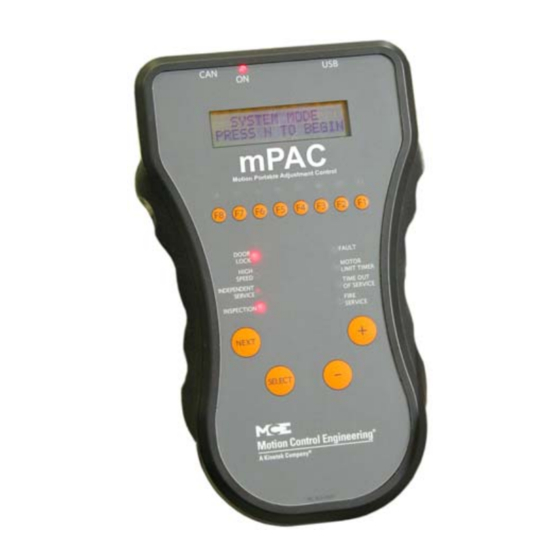
Final Adjustments Emergency or Standby Power Operation Two emergency power tests are described here. The first is for a car equipped with the TAPS (Traction Auxiliary Power Supply) from MCE. The second is for a car equipped with backup generator power. Note When performing emergency power related testing, ensure that the mPAC hand-held program- ming unit, if used, is not connected. -
Page 175: Backup Generator Power Test
Motion 4000 Final Tests 9. If TAPS shuts down before the elevator completes the rescue operation due to the timer set in parameter F1-1 “Backup Power Run Time,” extend the timer accordingly and per- form the test again. 10. If TAPS shuts down before the elevator completes the rescue operation due to battery voltage drop below F1-5 (error code E-04), let the TAPS charge for 8 hours before per- forming this test again. - Page 176 Final Adjustments Check the MCE drawings to verify that the car is properly connected to the emergency generator and that emergency power (F1, Extra Features Menu) is set up appropriately. A typical genera- tor connection is shown below. Figure 3.4 Typical Emergency Generator Connection 1.
-
Page 177: Final Adjustment
Motion 4000 Final Adjustment Final Adjustment Once you are satisfied that the car is operating accurately and safely, you will want to ride the car to verify the comfort of the ride and proper operation from a passenger perspective. 1. Place the car on Independent Service so that it will not respond to hall calls. - Page 178 Final Adjustments 3-56 Manual # 42-02-2P24...
-
Page 179: Section 4. User Interface
User Interface In this Section The default user interface to the Motion 4000 Traction Control is the LCD and keypad on the HC-MPU board. A hand-held user interface that functions like the LCD and keypad may also be provided. The hand-held user interface provides access when plugged into any CAN Bus con- nector in the system. - Page 180 User Interface • F2 — External Memory Mode: • View data stored in external memory. See page 4-53. • F3 — System Mode: • Building security. See Building Security Menu on page 4-53. • Controller system (fault bypass, data trap). See Controller System Menu on page 4-55.
-
Page 181: The Hc-Mpu Main Processor Unit
Motion 4000 The HC-MPU Main Processor Unit The HC-MPU Main Processor Unit Figure 4.1 HC-MPU Main Processor Unit Board J6: CPU B Debug M1: Ethernet Port A LCD Display J2: Keyboard Port J7: RS232 Port B J8: CPU-B JTAG J10: Ethernet Port B... - Page 182 User Interface Table 4.1 HC-MPU Board Switches Switches Description RSTA: Reset CPU A RSTB: Reset CPU B “-” minus push button - decrement setting “S” push button - select “+” plus push button - increment setting “N” push button - next Port Selection: RS232 Port A / Ethernet Port A DIP Function switches F5 through F8 DIP Function switches F1 though F4...
-
Page 183: Access Security
Motion 4000 Access Security Access Security Access security is an option. When access security is active, you are required to enter a pass- word before parameters can be adjusted. Password Program mode and System mode may be secured by an 8- digit, alpha-numeric code. -
Page 184: Diagnostic Mode
User Interface Diagnostic Mode With all Function switches down, Diagnostic Mode is active. The LCD displays status, position, an internal memory register address and its contents (flags). This mode allows you to select a memory register and view its contents. Memory contents can tell you the exact state of controller inputs and outputs, which is very valuable in troubleshooting. - Page 185 Motion 4000 Diagnostic Mode The Computer Internal Memory Chart (Table 4.3 on page 4-7) shows the meaning of data at dif- ferent addresses. For example, the internal memory display might look like this: At address 29; the data is 11110000. To figure out what this means, match up the data digits...
-
Page 186: Troubleshooting Example
User Interface Troubleshooting Example Examining the computer memory (as in the example above) is a useful step in troubleshooting. It is possible to find out if the controller is receiving input signals correctly and if it is sending proper output signals. It is also possible to look up each of the computer output and input sig- nals shown in the Job Prints. - Page 187 Motion 4000 Diagnostic Mode Table 4.4 Alphabetized Flags, Definitions, and Locations FLAG Definition Add Pos FLAG Definition Add Pos Other car alive output Fire phase 1 input 24 5 Alternate Parking Input FRSS Fire phase 1 flag 2D 3 AUTO...
- Page 188 User Interface Table 4.4 Alphabetized Flags, Definitions, and Locations FLAG Definition Add Pos FLAG Definition Add Pos Demand down flag 2A 8 NYDS New York door shortening flag 26 6 Demand up flag 2A 4 Passing floor gong output 2F 1 DNDO Down direction output Phase 1 return complete flag...
-
Page 189: F1: Program Mode
Motion 4000 F1: Program Mode F1: Program Mode These parameters define the building, floors and openings to be served, and other basic require- ments for the elevator. Put the car on Inspection and set Function switch F1 up (all others down) to enter Program mode. -
Page 190: Viewing Options Within A Menu
User Interface Viewing Options Within a Menu • To return to the top menu level, press the N and '+' buttons at the same time. • To scroll backwards, press the S and '-' push buttons at the same time. •... -
Page 191: Basic Features Menu
• If the controller is a duplex, it can operate a single car as a simplex or it can be con- nected to a second Motion 4000 controller and the two can operate as a duplex. • Both controllers must have duplex capability for duplexing to work. The option on each controller must be set to duplex. - Page 192 User Interface Caution Settings that affect the number of floors in the building, openings served per floor, discrete or serial (CE) position indicators, or the presence or absence of a serial car call board deter- mine the sequence of connections on Universal I/O boards used as “call boards” in the con- troller (UIO boards with addresses from 0 to 31).
- Page 193 Motion 4000 F1: Program Mode • ALT. PARKING FLOOR • Available only when an API input is programmed and a parking floor is set. Any land- ing can be chosen as the alternate parking floor. The car will go to the alternate parking floor when it is free of call demand and the API input is active.
-
Page 194: Fire Service Menu Options
User Interface • SERIAL CARTOP DOOR CONTROL? • Set to Yes if the door operator is connected to an HC-UIO board in the cartop box rather than using multiple connections through the traveler to the HC-CTL board in the controller cabinet. •... - Page 195 Motion 4000 F1: Program Mode • HONEYWELL FIRE OPERATION? • Only if FIRE SVCE. CODE option set to AUSTRALIA (See “FIRE SVCE. CODE” on page 4-16). If set to YES, Australia fire code will conform to Honeywell requirements. If set to NO, controller will conform to standard Australia code.
-
Page 196: Door Operation Menu Options
User Interface Door Operation Menu Options • NUDGING? • Enables Nudging Operation when doors are prevented from closing. During Nudging Operation, controller will turn ON the NUDG output to signal the door operator to close the doors at reduced speed. The NUDG output will stay ON for the amount of time the Nudging Timer specifies and then cycle off for the same amount of time. - Page 197 Motion 4000 F1: Program Mode • RETIRING CAM OPTION? • Select for elevators with retiring cams. Affects the car only when it is sitting at a floor. Without this option, the controller will wait until the doors are closed and locked before it turns OFF the door close signal.
- Page 198 User Interface • DIRECTIONAL PREFERENCE UNTIL DLK? • Causes car to maintain its present direction preference until the doors are fully closed. Otherwise, direction preference is maintained only until door dwell time expires. • FULLY MANUAL DOORS? • Set to YES if doors must be opened and closed manually. •...
- Page 199 Motion 4000 F1: Program Mode • DOORS TO OPEN ON ALT FIRE? • Choices are FRONT, REAR, or BOTH. Determines which door(s) should open once the car has completed an Alternate Fire return. • LEAVE DOORS OPEN ON CTL? • When set to YES, and the CTL (car to lobby) input is active, once the car has returned to the lobby the doors will remain open instead of cycling closed.
- Page 200 User Interface • REAR DOOR MECH. COUPLED? YES/NO • Set to YES if the rear car gate is mechanically coupled to the hallway doors. To satisfy A17.1-2000 code requirements, this option is used to qualify the HDR Redundancy fault when the Retiring Cam Option is set to YES and this option is set to YES. (See “RETIRING CAM OPTION?”...
-
Page 201: Timer Menu Options
Motion 4000 F1: Program Mode Timer Menu Options • SHORT DOOR TIMER (Range: 0.5-120.0 Seconds) • Determines length of time doors will stay open after being reopened by Photo Eye, Safety Edge, or Door Open button. • CAR CALL DOOR TIMER (Range: 0.5-120.0 Seconds) •... - Page 202 User Interface • DOOR HOLD INPUT TIMER (Range: 0-240 Seconds) • Timer used only if there is a DHLD (Door Hold) input to the controller (See “Spare Inputs Menu” on page 4-26). A Door Hold Open button is usually connected to this input.
-
Page 203: Gongs/Lanterns Menu
Motion 4000 F1: Program Mode Gongs/Lanterns Menu • MOUNTED IN HALL OR CAR? • Determines when lanterns and gongs are activated - as the car slows into the floor for hall mounted fixtures or after the door lock opens for car mounted fixtures. If both types of lanterns are used, the Hall option is recommended. -
Page 204: Spare Inputs Menu
User Interface Spare Inputs Menu The first 10 spare input terminals are located on the HC-CTL board. Additional spare inputs are available on each HC-UIO Universal Input/Output board. Please refer to “HC-UIO Universal Input/Output Board” on page 5-58. If your installation uses ICE-COP-2 or MC-CPI serial con- trol panel boards in the car, spare inputs are also available on these boards and will show up in the Spare Inputs menu as inputs to COP-Fx, CPI-F, CPI-Fx or COP-Rx, CPI-R depending upon the car control panel and rear door board configuration. - Page 205 Motion 4000 F1: Program Mode Table 4.6 Spare Inputs Menu Options Spare Inputs Menu Options 2AB relay coil monitoring input - If the 2AB relay is ON, the R2AB input will be OFF. R2AB must always be the opposite of 2AB. If not, the 2AB redundancy fault is logged and the ele- vator shuts down.
- Page 206 User Interface Table 4.6 Spare Inputs Menu Options Spare Inputs Menu Options Contactor Proof Input - Monitors the normal condition of motor/start contactors and will shut the car down if the contactor fails to make or break contact properly. Generates a Con- tactor Proofing Redundancy Failure message.
- Page 207 Motion 4000 F1: Program Mode Table 4.6 Spare Inputs Menu Options Spare Inputs Menu Options Door Lock Sensor Input - Monitors the state of the contacts in the landing door lock string. Power will be present on the DLS input when all the landing doors are closed and locked.
- Page 208 User Interface Table 4.6 Spare Inputs Menu Options Spare Inputs Menu Options EPRUN Emergency Power Run Input - Wired to the “Run” switch for emergency power car selection. The “dispatcher” in a duplex system will reference this input when deciding which car should be allowed to run on emergency power.
- Page 209 Motion 4000 F1: Program Mode Table 4.6 Spare Inputs Menu Options Spare Inputs Menu Options Hall Call Bus Failure input - input from the group controller indicating that the serial hall call bus has failed. Without hall call direction, local cars will begin “stop at each floor” operation to collect passengers and continue to provide service to the building.
- Page 210 User Interface Table 4.6 Spare Inputs Menu Options Spare Inputs Menu Options Light Load Input - When activated the elevator will only allow the number of car calls speci- fied by the Light Load Car Call Limit parameter to be registered. If more are registered, all car calls are canceled.
- Page 211 Motion 4000 F1: Program Mode Table 4.6 Spare Inputs Menu Options Spare Inputs Menu Options Redundancy 2L bus. Used to monitor the normally closed contact of an additional 2L relay. RBAB Redundancy monitoring input for the BAB relay contact. (See description of BAB input).
- Page 212 User Interface Table 4.6 Spare Inputs Menu Options Spare Inputs Menu Options Up Input (Attendant Service) - Used by an attendant during attendant service operation to establish a direction preference. Pushing the “UP” button in the car will activate this input, causing the computer to generate SUA (up direction preference) and DSHT (door shorten- ing) to close the doors.
-
Page 213: Spare Outputs Menu
Motion 4000 F1: Program Mode Spare Outputs Menu The first four spare output terminals are located on the HC-CTL board. Additional spare out- puts are available on each HC-UIO Universal Input/Output board. Please refer to “HC-UIO Universal Input/Output Board” on page 5-58. - Page 214 User Interface Table 4.7 Spare Outputs Menu Options Spare Outputs Menu Options 702-709 Front Down Hall Call indicators. Typically used for hall gongs or chimes and activated as the elevator levels into the associated landing. See drawings package. Do not use if a ded- icated HC-UIO board is used for Hall Call Indicators.
- Page 215 Motion 4000 F1: Program Mode Table 4.7 Spare Outputs Menu Options Spare Outputs Menu Options CR01R-CR8R Car Card Reader Outputs, rear landings. Indicates the associated card reader input has been activated (allowing car call registration to this rear landing). Once the call is regis- tered, output will remain active until call completed.
- Page 216 User Interface Table 4.7 Spare Outputs Menu Options Spare Outputs Menu Options Door Enable Inspection Stop Switch - Activated when front door operation is allowed. DEIS Deactivated if the elevator is on inspection or Test mode or if the door stop input has been activated.
- Page 217 Motion 4000 F1: Program Mode Table 4.7 Spare Outputs Menu Options Spare Outputs Menu Options FRCT Fire Service Phase II True Output - Like FRC, active when car is placed on Fire Service Phase II. Remains active after the car is taken off in-car firefighter status and until the car has recalled to the recall landing and the doors are preparing to open.
- Page 218 User Interface Table 4.7 Spare Outputs Menu Options Spare Outputs Menu Options HOSPH2 Hospital Phase 2. Activated when the car is at the hospital emergency recall floor. Remains active until the hospital in-car switch is turned off or the time interval that the car must wait for the in-car switch to be turned On expires.
- Page 219 Motion 4000 F1: Program Mode Table 4.7 Spare Outputs Menu Options Spare Outputs Menu Options OFRP One Floor Run Programmable - Active while making one-floor runs between adjacent floors designated in the Extra Features Menu (see “OFRP BETWEEN FLRS” on page 4-47).
-
Page 220: Extra Features Menu Options
User Interface Extra Features Menu Options • PI OUTPUT TYPE • Choose 1 WIRE PER FLOOR, BINARY BASE 1, BINARY BASE 0, GRAY CODE 1, or GRAY CODE 0 depending on the inputs required by the position indicator and whether the floor count begins with a zero value or a one value. •... - Page 221 Motion 4000 F1: Program Mode • LIGHT LOAD WEIGHING? / LIGHT LOAD CAR CALL LIMIT • Used only when the Light Load Weigher Input is activated. (See “Spare Inputs Menu” on page 4-26) To program this option: • Activate the LLI input.
- Page 222 User Interface • AUTOMATIC FLOOR STOP OPTION? / AUTOMATIC STOP FLOOR #? • If you want to use this option, set to a specific floor number. The car will automatically stop at that floor on any run that would normally pass the floor. •...
- Page 223 Motion 4000 F1: Program Mode • HOSPITAL EMERG. OPERATION? • When selected, enables Hospital Emergency Operation. Typically, a hospital emer- gency call switch is installed at each floor where this service is desired. • If you do not have Hospital Emergency Service Operation, set the option to NO by pressing the S button.
- Page 224 User Interface • FIRE BYPASSES HOSPITAL? • Set to YES if Hospital Service is used for VIP, Priority or Commandeering Service. Set this option to NO if Hospital Service is truly used for Hospital Service. • HIGH SPEED DELAY AFTER RUN? •...
- Page 225 Motion 4000 F1: Program Mode • ATS. BYPASS SECURITY? YES / NO • Determines if Elevator Security is bypassed when the car is on Attendant Service (available only when Security and Attendant Service are enabled). • CAR TO FLOOR RETURN FLOOR •...
- Page 226 User Interface • RETAIN CALLS ON CTL / CTF? • No: If Car To Lobby or Car To Floor are activated, the car will first service registered car calls then move to the recall floor. Hall calls will be canceled. •...
-
Page 227: Additional Car Options
Motion 4000 F1: Program Mode • EQ SHUTDOWN AT LANDING? • If yes, when the EQI input is activated, the elevator will proceed to the nearest landing, stop, open its doors, and shut down. • If no, the elevator will react as above but will return to service rather than shutting down. -
Page 228: F2: External Memory Mode
User Interface F2: External Memory Mode Access External Memory by placing Function Switch F2 in the Up position (all others down). External Memory mode is used to view memory addresses in HC- MPU board RAM. The external memory address is denoted by the letters DA (Data Address). - Page 229 Motion 4000 F2: External Memory Mode Table 4.8 Computer External Memory Chart HALL CALLS CAR CALLS 0140: 601R/UC1R 601/UC1 101R/CC1R 101/CC1 0141: 602R/UC2R 602/UC2 502R/DC2R 502/DC2 102R/CC2R 102/CC2 0142: 603R/UC3R 603/UC3 503R/DC3R 503/DC3 103R/CC3R 103/CC3 0143: 604R/UC4R 604/UC4 504R/DC4R 504/DC4...
- Page 230 User Interface Table 4.9 Hospital Call and Eligibility Memory Chart HOSPITAL CALL ELIGIBILITY HOSPITAL CALLS ASSIGNED REGISTERED OTHER CAR THIS CAR HOSPITAL CALLS HOSPITAL CALLS REAR FRONT REAR FRONT REAR FRONT REAR FRONT 0240: ECR1 Floor # 1 0241: ECR2 Floor # 2 0242: ECR3...
-
Page 231: F3: System Mode
Motion 4000 F3: System Mode F3: System Mode System mode allows the user to change certain system-wide options that do not require the car to be on Inspection. To enter System mode: • Move the F3 switch to the up position (all others down). -
Page 232: Viewing The Building Security Menu
User Interface Viewing The Building Security Menu 1. Place the F3 switch in the up position (all other switches down). The following display appears: 2. Press the N push button. The following display appears: Programming And Viewing The Security Codes 1. -
Page 233: Controller System Menu
Motion 4000 F3: System Mode Controller System Menu This menu provides real time position and speed information and allows you to bypass faults in both Automatic and Inspection operating modes when required for system tests. It also pro- vides access to a data trap required by ASME A17.2000 code. -
Page 234: Passcode Request Menu
User Interface Passcode Request Menu The Passcode Request Operation can be used to require password entry to run the car on any mode of operation other than Inspection. Note If a passcode has not been programmed, the Passcode Request Menu will not appear. If a passcode has been programmed, the LCD screen will flash the “PASSCODE REQUEST”... -
Page 235: Activating The Passcode
Motion 4000 F3: System Mode Activating the Passcode With the Passcode Request menu displayed, press S. If Passcode Request Oper- ation is not activated, the following display appears: • Press S to toggle from “NO” to “YES.” • Press N with “YES” displayed to activate Passcode Request Operation and exit this screen. -
Page 236: Adjusting Thresholds
User Interface Adjusting Thresholds Typical values for load thresholds are shown below. Thresholds are user-adjustable. To adjust thresholds 1. Enter SYSTEM mode (F3 up, all others down). 2. Press N until LOAD WEIGHER THRESHOLDS appears on the LCD. 3. Press S to display the load threshold you wish to set. 4. - Page 237 Motion 4000 F3: System Mode 8. If the Extra Features Menu Option “Analog Load Weigher?” is set to MCE, the car will learn the empty car value once and display: • EMPTY CAR LEARN PROCESS COMPLETED. PRESS S TO CONT.
- Page 238 User Interface F4: Messages and Floor Labels To access: F4 switch up; all others down. • Modify Floor Labels • FLOOR LABEL FOR LANDING 01: _ _ _ • Use + or - keys to change landing • Use S key to move to first label field •...
-
Page 239: F4: Messages And Floor Labels
Motion 4000 F4: Messages and Floor Labels • Initialize all Labels • DEFAULT LABELS [S] - Yes [N] - No • Use this function to initialize all labels to factory defaults. • If you do not wish to complete the command, press and hold -, then press N to exit. -
Page 240: F5 Menus
User Interface F5 Menus The F5 switch provides access the three menus: • Controller Utilities Menu • A way to register front and rear car calls from the controller or the hand-held device • Allows you to view and set date and time for controller time stamping •... -
Page 241: Controller Utilities
Motion 4000 F5 Menus Controller Utilities Car Call Registration CONTROLLER *UTILITIES MENU* + and N + and N + and N FRONT CALL FRONT CAR CALL: FRONT CAR CALL: FRONT CAR CALL: + and N - REGISTRATION - LANDING 01 [OFF]... -
Page 242: View Event Log
User Interface View Event Log The event log tracks the most recent system events; each with date and time stamp. Event “01” is the most recent event, with older events numbered “02” through “99” respectively. 1. Press S to view the event log. An event number and the associated event (usually scrolling due to message length) are dis- played on the top line of the display. -
Page 243: Clear Event Log
Motion 4000 F5 Menus Clear Event Log This allows you to clear the events from the event log. 1. Press S to select the clear function. A prompt will appear allowing you to back out without clearing events (Yes/No). 2. To clear the log press the S button when prompted. -
Page 244: Mpi Diagnostic Menu
User Interface MPI Diagnostic Menu These diagnostics allow you to view car motion parameters (speed/distance) as the car moves through the hoistway. This information in turn will help you make ride adjustments or trouble- shoot ride issues. The initial screen will show either METRIC or ENGLISH units. 1. -
Page 245: Mpi-A Diagnostics
Motion 4000 F5 Menus MPI-A Diagnostics The following diagnostic information can be viewed for Safety Processor A on the TC-MPI Motion Processor Interface board. Table 4.12 MPI-A Diagnostics Address Item Notes Front openings Rear openings Floors Bottom floor Top floor... - Page 246 User Interface Table 4.12 MPI-A Diagnostics Address Item Notes Speed @ UNTS1 over-speed fault Speed @ UNTS2 over-speed fault Speed @ UNTS3 over-speed fault Speed @ UNTS4 over-speed fault Speed @ UNTS5 over-speed fault Runtime distance @ DETS Runtime distance @ DNTS1 Runtime distance @ DNTS2 Runtime distance @ DNTS3 Runtime distance @ DNTS4...
- Page 247 Motion 4000 F5 Menus Table 4.12 MPI-A Diagnostics Address Item Notes Fault runs Floor zone Position bypass count Position pass count System position count Absolute position count Position lower sequence Position upper sequence Position lower value Position upper value Landing code...
- Page 248 User Interface Table 4.12 MPI-A Diagnostics Address Item Notes Port E inputs: 01 = SW2-1 02 = SW2-2 03 = SW2-3 04 = SW2-4 05 = (n/a) 06 = (n/a) 07 = (n/a) 08 = (n/a) 09 = (n/a) 10 = (n/a) 11 = (n/a) 12 = (n/a) 13 = (n/a)
- Page 249 Motion 4000 F5 Menus Table 4.12 MPI-A Diagnostics Address Item Notes Port C outputs: 01 = (n/a) 02 = (n/a) 03 = (n/a) 04 = (n/a) 05 = (n/a) 06 = (n/a) 07 = (n/a) 08 = (n/a) 09 = (n/a)
- Page 250 User Interface Table 4.12 MPI-A Diagnostics Address Item Notes Faults (01 - 16): 01 = Maximum position offset fault 02 = Minimum position offset fault 03 = Landing system fault (emergency brake dropped) 04 = Landing system communication loss fault 05 = Unintended motion 06 = SPC is offline 07 = SPB is offline...
- Page 251 Motion 4000 F5 Menus Table 4.12 MPI-A Diagnostics Address Item Notes Faults (49 - 64): (n/a) 16 = BRE (MPI-A) 15 = DRE (MPI-A) 14 = PME (MPI-A) 13 = DRE (MPI-C) 12 = BRE (MPI-C) 11 = PME (MPI-C)
- Page 252 User Interface Table 4.12 MPI-A Diagnostics Address Item Notes 16 = UETS status 15 = UTS1 status 14 = UNTS2 status 13 = UNTS3 status 12 = UNTS4 status 11 = UNTS5 status 10 = DETS status 09 = DTS1 status 08 = DNTS2 status 07 = DNTS3 status 06 = DNTS4 status...
-
Page 253: Mpi-B Diagnostics
Motion 4000 F5 Menus Table 4.12 MPI-A Diagnostics Address Item Notes Up distance @ 60% of contract speed Up distance @ 50% of contract speed Up distance @ 40% of contract speed Up distance @ 30% of contract speed Up distance @ 20% of contract speed Up distance @ 10% of contract speed Example: 1.019M. - Page 254 User Interface Table 4.13 MPI-B Diagnostics Address Item Notes Raw speed feedback Speed @ leveling over-speed fault Speed @ inspection over-speed fault Speed @ contract over-speed fault Runtime speed @ DETS Runtime speed @ DNTS1 Runtime speed @ DNTS2 Runtime speed @ DNTS3 Runtime speed @ DNTS4 Runtime speed @ DNTS5 Runtime speed @ UETS...
- Page 255 Motion 4000 F5 Menus Table 4.13 MPI-B Diagnostics Address Item Notes Distance @ DNTS3 position fault Distance @ DNTS4 position fault Distance @ DNTS5 position fault Distance @ UETS position fault Distance @ UNTS1 position fault Distance @ UNTS2 position fault...
- Page 256 User Interface Table 4.13 MPI-B Diagnostics Address Item Notes Port B inputs: 01 = (n/a) 02 = (n/a) 03 = (n/a) 04 = (n/a) 05 = UETS 06 = DETS 07 = (n/a) 08 = (n/a) 09 = EGOK 10 = RGR1 11 = RGR2 12 = RGOK 13 = (n/a)
- Page 257 Motion 4000 F5 Menus Table 4.13 MPI-B Diagnostics Address Item Notes Port A outputs: 01 = (n/a) 02 = (n/a) 03 = DIA2B 04 = DIA1B 05 = DIA7B 06 = DIA7B 07 = (n/a) 08 = (n/a) 09 = (n/a)
- Page 258 User Interface Table 4.13 MPI-B Diagnostics Address Item Notes Port G outputs: 01 = (n/a) 02 = (n/a) 03 = DIA4B 04 = DIA3B 05 = (n/a) 06 = (n/a) 07 = (n/a) 08 = (n/a) 09 = (n/a) 10 = (n/a) 11 = (n/a) 12 = (n/a) 13 = (n/a)
- Page 259 Motion 4000 F5 Menus Table 4.13 MPI-B Diagnostics Address Item Notes Faults (17 - 32): 01 = DETS over-speed 02 = DETS position error 03 = Emergency brake cycle test fault 04 = PMDD contactor pick monitor fault 05 = PMDD contactor drop monitor fault...
- Page 260 User Interface Table 4.13 MPI-B Diagnostics Address Item Notes 16 = (n/a) 15 = (n/a) 14 = (n/a) 13 = Up slowdown 12 = Down slowdown 11 = Up direction limit 10 = Down direction limit 09 = Front level up 08 = Front door zone 07 = Front level down 06 = Rear level up...
- Page 261 Motion 4000 F5 Menus Table 4.13 MPI-B Diagnostics Address Item Notes Down distance @ 60% of contract speed Down distance @ 50% of contract speed Down distance @ 40% of contract speed Down distance @ 30% of contract speed Down distance @ 20% of contract speed...
-
Page 262: Mpi-C Diagnostics
User Interface MPI-C Diagnostics The following diagnostic information can be viewed for Main Processor on the TC-MPI Motion Processor Interface board. Table 4.14 MPI-C Diagnostics Address Item Notes Front openings Rear openings Floors Bottom floor Top floor Bottom landing Top landing Bottom position Top position Raw position... - Page 263 Motion 4000 F5 Menus Table 4.14 MPI-C Diagnostics Address Item Notes Up distance @ 10% of contract speed Actual landing Target landing Logical landing Successful runs Fault runs Control RPM Position Bypass Position Pass Drive: 17-32 = Control command 01-16 = Control input...
- Page 264 User Interface Table 4.14 MPI-C Diagnostics Address Item Notes Port E signal: 01 = MDRE 02 = (n/a) 03 = (n/a) 04 = (n/a) 05 = (n/a) 06 = (n/a) 07 = (n/a) 08 = (n/a) 09 = (n/a) 10 = (n/a) 11 = (n/a) 12 = (n/a) 13 = (n/a)
- Page 265 Motion 4000 F5 Menus Table 4.14 MPI-C Diagnostics Address Item Notes Port E input: 01 = MDRE 02 = (n/a) 03 = (n/a) 04 = (n/a) 05 = (n/a) 06 = (n/a) 07 = (n/a) 08 = (n/a) 09 = (n/a)
- Page 266 User Interface Table 4.14 MPI-C Diagnostics Address Item Notes Port D output: 01 = FBS 02 = EQIND 03 = PME 04 = BRE 05 = DRE 06 = BRC 07 = (n/a) 08 = (n/a) 09 = (n/a) 10 = (n/a) 11 = (n/a) 12 = (n/a) 13 = (n/a)
- Page 267 Motion 4000 F5 Menus Table 4.14 MPI-C Diagnostics Address Item Notes 01 \ 02 | 03 | 04 \ Diagnostic switches 05 / 06 | 07 | 08 / 09 = Encoder fault 10 = Encoder channel Z 11 = Encoder channel A...
- Page 268 User Interface Table 4.14 MPI-C Diagnostics Address Item Notes 01 = Near top 02 = Near bottom 03 = High speed 04 = Up direction limit 05 = Down direction limit 06 = Wind 07 = (n/a) 08 = (n/a) 09 = (n/a) 10 = (n/a) 11 = (n/a)
- Page 269 Motion 4000 F5 Menus Table 4.14 MPI-C Diagnostics Address Item Notes 16 = Up 15 = Down 14 = High speed 13 = (n/a) 12 = (n/a) 11 = (n/a) 10 = (n/a) 09 = Normal run 08 = Correction run...
- Page 270 User Interface Table 4.14 MPI-C Diagnostics Address Item Notes Example: 1.019M. Processed raw position for MPI- Upper Elgo sensor position in m/in B and MPI-C. Median for MPI-A. Example: 0.859M. Processed raw position for MPI- Lower Elgo sensor position in m/in A and MPI-C.
-
Page 271: Edg Diagnostics
Motion 4000 F5 Menus EDG Diagnostics See “MPI Diagnostic Menu” on page 4-66 for use instructions. Table 4.15 LS-EDGE Diagnostics Address Floor number Diagnostic Sensor Flags Encoder Pair 1 Encoder Pair 1 Encoder Pair 1 Encoder Pair 1 Main Encoder... - Page 272 User Interface Table 4.15 LS-EDGE Diagnostics Address Floor number Diagnostic Measured magnet length in counts Floor height in counts DLM edge in counts ULM_edge in counts Front Floor 7 Floor height (inch or mm) Measured magnet length in counts Floor height in counts DLM edge in counts ULM_edge in counts Front Floor 8...
- Page 273 Motion 4000 F5 Menus Table 4.15 LS-EDGE Diagnostics Address Floor number Diagnostic Floor height in counts DLM edge in counts ULM_edge in counts Front Floor 14 Floor height (inch or mm) Measured magnet length in counts Floor height in counts...
- Page 274 User Interface Table 4.15 LS-EDGE Diagnostics Address Floor number Diagnostic DLM edge in counts ULM_edge in counts Front Floor 21 Floor height (inch or mm) Measured magnet length in counts Floor height in counts DLM edge in counts ULM_edge in counts Front Floor 22 Floor height (inch or mm) Measured magnet length in counts...
- Page 275 Motion 4000 F5 Menus Table 4.15 LS-EDGE Diagnostics Address Floor number Diagnostic ULM_edge in counts Front Floor 28 Floor height (inch or mm) Measured magnet length in counts Floor height in counts DLM edge in counts ULM_edge in counts Front Floor 29...
- Page 276 User Interface Table 4.15 LS-EDGE Diagnostics Address Floor number Diagnostic Front Floor 35 Floor height (inch or mm) Measured magnet length in counts Floor height in counts DLM edge in counts ULM_edge in counts Front Floor 36 Floor height (inch or mm) Measured magnet length in counts Floor height in counts DLM edge in counts...
- Page 277 Motion 4000 F5 Menus Table 4.15 LS-EDGE Diagnostics Address Floor number Diagnostic Front Floor 42 Floor height (inch or mm) Measured magnet length in counts Floor height in counts DLM edge in counts ULM_edge in counts Front Floor 43 Floor height (inch or mm)
- Page 278 User Interface Table 4.15 LS-EDGE Diagnostics Address Floor number Diagnostic Measured magnet length in counts Floor height in counts DLM edge in counts ULM_edge in counts Front Floor 50 Floor height (inch or mm) Measured magnet length in counts Floor height in counts DLM edge in counts ULM_edge in counts Front Floor 51...
- Page 279 Motion 4000 F5 Menus Table 4.15 LS-EDGE Diagnostics Address Floor number Diagnostic Floor height in counts DLM edge in counts ULM_edge in counts Front Floor 57 Floor height (inch or mm) Measured magnet length in counts Floor height in counts...
- Page 280 User Interface Table 4.15 LS-EDGE Diagnostics Address Floor number Diagnostic DLM edge in counts ULM_edge in counts Front Floor 64 Floor height (inch or mm) Measured magnet length in counts Floor height in counts DLM edge in counts ULM_edge in counts Rear Floor 1 Floor height (inch or mm) Measured magnet length in counts...
- Page 281 Motion 4000 F5 Menus Table 4.15 LS-EDGE Diagnostics Address Floor number Diagnostic ULM_edge in counts Rear Floor 7 Floor height (inch or mm) Measured magnet length in counts Floor height in counts DLM edge in counts ULM_edge in counts Rear Floor 8...
- Page 282 User Interface Table 4.15 LS-EDGE Diagnostics Address Floor number Diagnostic Rear Floor 14 Floor height (inch or mm) Measured magnet length in counts Floor height in counts DLM edge in counts ULM_edge in counts Rear Floor 15 Floor height (inch or mm) Measured magnet length in counts Floor height in counts DLM edge in counts...
- Page 283 Motion 4000 F5 Menus Table 4.15 LS-EDGE Diagnostics Address Floor number Diagnostic Rear Floor 21 Floor height (inch or mm) Measured magnet length in counts Floor height in counts DLM edge in counts ULM_edge in counts Rear Floor 22 Floor height (inch or mm)
- Page 284 User Interface Table 4.15 LS-EDGE Diagnostics Address Floor number Diagnostic Measured magnet length in counts Floor height in counts DLM edge in counts ULM_edge in counts Rear Floor 29 Floor height (inch or mm) Measured magnet length in counts Floor height in counts DLM edge in counts ULM_edge in counts Rear Floor 30...
- Page 285 Motion 4000 F5 Menus Table 4.15 LS-EDGE Diagnostics Address Floor number Diagnostic Floor height in counts DLM edge in counts ULM_edge in counts 1000 Rear Floor 36 Floor height (inch or mm) 1001 Measured magnet length in counts 1002 Floor height in counts...
- Page 286 User Interface Table 4.15 LS-EDGE Diagnostics Address Floor number Diagnostic 1063 DLM edge in counts 1064 ULM_edge in counts 1070 Rear Floor 43 Floor height (inch or mm) 1071 Measured magnet length in counts 1072 Floor height in counts 1073 DLM edge in counts 1074 ULM_edge in counts...
- Page 287 Motion 4000 F5 Menus Table 4.15 LS-EDGE Diagnostics Address Floor number Diagnostic 1134 ULM_edge in counts 1140 Rear Floor 50 Floor height (inch or mm) 1141 Measured magnet length in counts 1142 Floor height in counts 1143 DLM edge in counts...
- Page 288 User Interface Table 4.15 LS-EDGE Diagnostics Address Floor number Diagnostic 1210 Rear Floor 57 Floor height (inch or mm) 1211 Measured magnet length in counts 1212 Floor height in counts 1213 DLM edge in counts 1214 ULM_edge in counts 1220 Rear Floor 58 Floor height (inch or mm) 1221...
-
Page 289: System Can Bus
Motion 4000 F5 Menus System CAN Bus The System CAN Bus/Data Viewing screen allows you to check the working status of the inputs and outputs of any Car Panel Interface board in the system. SYSTEM CAN BUS *DATA VIEWING* • Press S to enter the menu... -
Page 290: Monitoring And Reporting Menu
User Interface Monitoring and Reporting Menu If the controller is configured for monitoring or reporting connections through Ethernet, this menu is used to set up the port and to view communication statistics for diagnostic purposes. • With “Monitoring and Reporting Menu” displayed, press S to enter the menu. The first screen provides a way to exit the menu without making changes. -
Page 291: Diagnostics, Refresh, Reset
Motion 4000 F5 Menus • The gateway screen allows the gateway address to be set: See note below. Note Any time you make a change to IP address, Subnet Mask, or Gateway Address, you must reset the HC-CHP board (Device) or the XPort. Refer to the information following. - Page 292 User Interface • The Receive/Transmit screen monitors the current number of receive and transmit mes- sages in the XPort queue, the peak number of messages in that queue, and the maximum acceptable number of messages in each queue. • The error diagnostic displays those data points being checked for change. E = Events P = Parameters M = Monitors...
-
Page 293: Terminal Limit Utilities Menu
Motion 4000 F5 Menus • Refresh XPort allows you to trigger an immediate data gathering cycle to ensure you are seeing the latest XPort information (IP address, Gateway address, Subnet Mask, and Type of controller). • The TFTP Status screen allows you to provide permission for an FTP updater to update the monitoring software on this controller. -
Page 294: Fcl Brake Unit Utilities Menu
TC-FCL parameters or calibrate a selected mod- ule TC-FCL for use on the Motion 4000 controller. Navigate to this menu using the N button, then select it using the S button to access sub-menus. Navigate between sub-menus using the N button. -
Page 295: F6: Hoistway Learn Operations
Motion 4000 F6: Hoistway Learn Operations F6: Hoistway Learn Operations The F6 menu provides a process to learn the floor levels and counterweight position for the building. The process is different depending on the type of landing/positioning system for the job. -
Page 296: F7: Parameters Adjust
User Interface F7: Parameters Adjust Through the F7 menu, you learn the terminal switches, drive, and machine characteristics that influence speed and position computation. You start by uploading all parameters from the TC- MPI Motion Processor Interface board, then modify as necessary and save. Important Once set at the factory, F7 parameters are protected by positioning a jumper on the HC-CTL board. -
Page 297: Controller Parameter/Drive Parameter Interaction
Motion 4000 F7: Parameters Adjust Controller Parameter/Drive Parameter Interaction There are very important things to consider about the interaction between motion parameters set on the drive and the setting or collection of motion parameters on the controller. • Drive parameters LF.20 Contract Speed and LF.11 Motor RPM determine the drive’s Esti- mated Gear Ratio, LF.25. -
Page 298: Using Id Numbers For Direct Parameter Access
User Interface Using ID Numbers for Direct Parameter Access All F7 parameters have a fixed ID number. When you are in the F7 menu, you can scroll to a particular ID by: • Press and hold N (Next) to increment to the desired ID. •... - Page 299 Motion 4000 F7: Parameters Adjust Table 4.17 F7 Parameters Item Default Notes Floor 39 -12.0 in +4560.0 in +12000.0 in Floor 40 -12.0 in +4680.0 in +12000.0 in Floor 41 -12.0 in +4800.0 in +12000.0 in Floor 42 -12.0 in +4920.0 in...
- Page 300 User Interface Table 4.17 F7 Parameters Item Default Notes UNTS1 delta distance -120.0 in +6.0 in +120.0 in UNTS1 delta low speed 0 fpm 0 fpm +900 fpm UNTS1 delta high speed 0 fpm 0 fpm +900 fpm UNTS2 speed 0 fpm 0 fpm +900 fpm...
- Page 301 Motion 4000 F7: Parameters Adjust Table 4.17 F7 Parameters Item Default Notes DNTS3 delta distance -120.0 in +6.0 in +120.0 in DNTS3 delta low speed 0 fpm 0 fpm +900 fpm DNTS3 delta high speed 0 fpm 0 fpm +900 fpm...
- Page 302 User Interface Table 4.17 F7 Parameters Item Default Notes Re-leveling speed 0 fpm +6 fpm +25 fpm Leveling distance 0.0 in +0.9 in +9.0 in Re-leveling distance 0.0 in +0.9 in +9.0 in Proximity distance 0.0 in +18.0 in +120.0 in Leveling dead zone dis- 0.0 in +0.5 in...
- Page 303 Motion 4000 F7: Parameters Adjust Table 4.17 F7 Parameters Item Default Notes Magnetek drives only. Time in milliseconds during which the drive should continue to exert Speed Drop Delay 800 ms motor control after the car has achieved the floor and before the brake has dropped.
-
Page 304: Floor Heights
User Interface Parameters Floor Heights Parameters 1 through 64 represent floor heights within the building. Floor heights are stored as absolute values referenced to the first floor, which is always initially displayed as 0.0 inches. You have already learned all floor heights in the building (F6), so they will be displayed as you progress. -
Page 305: Counterweight Position, 67
Depending upon job speed, not all switch positions may be used so there is also the option to set a switch position to “Unused.” The illustration below shows the switches that may be used on Motion 4000 (ETS, NTS-1, NTS-2, NTS-3, NTS-4, and NTS-5). Table 4.18 Hoistway Switch Requirements... - Page 306 User Interface • Use the + or - buttons to select the kind of switch used on your job (Virtual/Physical/ Unused). For jobs below 400 FPM, NTS-1 is used as the Slowdown Limit switch. As a result, ETS and NTS-1 should be set to “virtual” and all other switches should be set to “unused.”.
-
Page 307: Speed Related Parameters
Motion 4000 F7: Parameters Adjust Speed Related Parameters Follow the learn operations described in Section 3 of this manual to set up hoistway switches. The A processor diagnostics table, MPI-A Diagnostics on page 4-67, is very helpful in allowing you to view actual running conditions in the hoistway (speed at switches, etc.), and test your settings as you make adjustments. -
Page 308: Normal Terminal Switch Parameter Explanations
User Interface Normal Terminal Switch Parameter Explanations At contract speeds below 400 FPM, up and down normal terminal switches are not used as tra- ditional limit switches. Instead, Normal Terminal Limit switches 2 - 5 are set to “unused” through controller F7 parameters and Normal Terminal Limit switches 1 Up and 1 Down are used as Terminal Slowdown Switches. -
Page 309: Unts1 Speed, 79
Motion 4000 F7: Parameters Adjust UNTS1 Speed, 79 Learned value (percentage of Contract Speed) at which the car should be traveling when encountering this switch during a normal run to the terminal in order for normal stopping means to properly slow and stop the car. -
Page 310: Dets Speed, 104
User Interface DETS Speed, 104 This is the speed, in feet per minute, which the car must be below when opening the Down Emergency Terminal Switch. This value, plus the value of the DETS Delta Speed settings, must not exceed 95% of Contract Speed. Note DETS Switch: Depending upon the speed of the job, the Emergency Terminal Switch may be positioned differently. -
Page 311: Brake Pick Delay, 133
Motion 4000 F7: Parameters Adjust DNTS2, 3, 4, 5 Speed, Distance, and Delta just as with DNTS-1 but with distances and speeds per your Contract Speed. For any switch that has been set to “unused”, parameters can all be set to 0.0. -
Page 312: Brake Drop Delay, 136
User Interface Brake Drop Delay, 136 The delay, in milliseconds, that the brake should be delayed from dropping after the speed command is dropped. The goal is to avoid dropping the brake until the motor has just stopped moving. The default time of 250 milliseconds is a good starting point. -
Page 313: Contract Overspeed, 145
Motion 4000 F7: Parameters Adjust Contract Overspeed, 145 The setting in feet per minute above contract speed at which a contract overspeed is detected and an emergency stop initiated. Generally set to about 8% above contract speed with variance due to the tracking accuracy of the drive/motor. -
Page 314: Inspection Speed (Reduced), 156
User Interface Inspection Speed (Reduced), 156 If the car reduces inspection speed upon encountering normal or emergency terminal speed switches, enter that reduced speed here. Correction Speed, 157 If the car should lose position, this is the speed at which it will proceed to a known point to re-establish position. -
Page 315: Standard Deceleration, 169
Motion 4000 F7: Parameters Adjust Standard Deceleration, 169 Determines the maximum deceleration for this profile. The maximum value is typically 4.0 ft/s and the minimum is usually not less than 2.0 ft/s with more common values ranging from 2.75 ft/s to 3.75 ft/s... - Page 316 F5-GLS50 (gearless machine). Otherwise, select KEB F5-GRD49 (geared) or KEB F5GLS49 (gearless). Brake Type, 185 Motion 4000 may be configured with one or two brake modules or a straight brake drop / brake pick brake (Discrete). Select the controller brake configuration. Emergency Brake, 186 This setting selects or disables the emergency brake option.
- Page 317 Motion 4000 F7: Parameters Adjust Unintended Motion, 188 Determines where unintended motion is detected. • Level Zone: Detected when car moves out of the leveling zone. • Door Zone: Detected when car moves out of the door zone. Following Error, 189 Following error sets the allowed margin of deviation from com- manded speed as a percentage of that speed.
- Page 318 • Dynamic: Compensates for drive control lag during the deceleration stage only using a variable percentage of the value entered in parameter 140, Profile Advance. Recom- mended to provide backwards compatibility when upgrading Motion 4000 software in existing installations. (Previous versions always used Dynamic compen- sation;...
- Page 319 Motion 4000 F7: Parameters Adjust Directional Limit Type, 202 Virtual/Physical • Virtual: Directional limits remain software based and operate normally based upon the programmed distance above/below the top/bottom terminal landings. • Physical: The U/DETS terminals on the TC-MPI board are used for connection to mechan- ical direction limit switches.
- Page 320 User Interface F8: Software Revision Displays current software level for each of the controllers processors. • PTHC D VER # T08.01-0042 Note The “boot loader” IC polls each processor as the controller is powering up, ensuring that each has the right software. The software version for the boot loader itself is displayed in a scrolling message as the controller is powering up.
- Page 321 Motion 4000 F1 & F8: Board Software Versions F1 & F8: Board Software Versions When both F1 and F8 switches are up, board software version numbers are visible. This can be helpful when troubleshooting with an MCE technician. • Press N button for versions: •...
- Page 322 User Interface 4-144 Manual # 42-02-2P24...
- Page 323 Troubleshooting In This Section This section contains troubleshooting information to help you correct problems. If you are reading this on a computer, you can click on blue text to jump to more information about the topic. • Status and Error Messages: Table includes a description and troubleshooting tips for each message.
- Page 324 Troubleshooting Status and Error Messages In Diagnostic Mode, the top line of the LCD displays eleva- tor status. The message scrolls if it is too long to be displayed all at once. There are status messages for operating modes (e.g., FIRE SERVICE PHASE 1 - MAIN) and for error condi- tions (e.g., SAFETY CIRCUIT IS OPEN).
- Page 325 Motion 4000 Status and Error Messages Note When troubleshooting inputs, use built-in diagnostics to view memory registers so that you can see the actual state of the input. Please refer to “Troubleshooting Example” on page 4-8. Table 5.1 Status and Error Messages...
- Page 326 Troubleshooting Table 5.1 Status and Error Messages Scrolling Message - Special Event Message ATD INPUT FAILURE Description: The Top Down Access (ATD) switch is at 120VAC when the 2HA bus is low. Troubleshooting: 1. Check for incorrect wiring or short on the HC-CTL board ATD input and 2HA or 2 bus. 2.
- Page 327 Motion 4000 Status and Error Messages Table 5.1 Status and Error Messages Scrolling Message - Special Event Message BOTTOM FLOOR OR TOP FLOOR DEMAND Description: The controller is trying to establish car position by sending it to either the top or the bottom.
- Page 328 Troubleshooting Table 5.1 Status and Error Messages Scrolling Message - Special Event Message CAR DOOR BYPASS SW. FAILURE Description: Indicates that the car door bypass switch has failed. Troubleshooting: 1. Cycle the HC-CTL board car door bypass switch a few times to exercise it. Verify that it is fully in the ON or OFF position.
- Page 329 Motion 4000 Status and Error Messages Table 5.1 Status and Error Messages Scrolling Message - Special Event Message DCLCR INPUT FAILURE Description: The Rear Door Close Limit Contact (DCLCR) input monitors the rear door closed contacts. DCLCR should be 120VAC during bottom rear access operation when the Bottom Access switch is toggled to the up or down position.
- Page 330 Troubleshooting Table 5.1 Status and Error Messages Scrolling Message - Special Event Message DOOR CLOSE PROTECTION TIMER ELAPSED Description: Failure to lock the doors detected. This condition exists when the doors have closed (DCLC = 1 or DCL = 0/DPM=1) and demand exists for the car to move (DCP=1), but the doors have not locked (DLK = 0) within 60 seconds.
- Page 331 Motion 4000 Status and Error Messages Table 5.1 Status and Error Messages Scrolling Message - Special Event Message DRIVE FAULT Description: This fault indicates that the controller has detected a DFLT input. The car will perform an emergency stop with the motor contactor and brake contactor immediately dropped.
- Page 332 Troubleshooting Table 5.1 Status and Error Messages Scrolling Message - Special Event Message FCL 1 - 4 - AUX IGBT STUCK CLOSED Description: The addressed brake module auxiliary IGBT is stuck in the closed position. This fault is trig- gered if the voltage across the Aux IGBT is insufficient to activate the monitoring circuit during dissipate mode.
- Page 333 Motion 4000 Status and Error Messages Table 5.1 Status and Error Messages Scrolling Message - Special Event Message FCL 1 - 4 LOAD EXTREME UNDER CURRENT Description: The addressed brake module has detected that delivered current is less than 40% of the learned operating current.
- Page 334 Please refer to “FCL Power Data Menu” on page 4-116. FCL 1 - 4 - NOT CALIBRATED Description: The addressed module is not calibrated to operate with the Motion 4000 system. Troubleshooting: Calibrate the module. Please refer to “Calibration (CAN Only)” on page 5-87.
- Page 335 Motion 4000 Status and Error Messages Table 5.1 Status and Error Messages Scrolling Message - Special Event Message FIRE SERVICE PHASE 1 - MAIN Description: The car is returning to the main fire return landing. The FRS input is low or the FRON or FRON2 inputs are high.
- Page 336 Troubleshooting Table 5.1 Status and Error Messages Scrolling Message - Special Event Message GOVERNOR SWITCH OPEN Description: The overspeed governor has activated, opening the safety circuit. Troubleshooting: Check the overspeed governor. GROUP TO CAR COMMUNICATION LOSS Description: The car controller has detected a loss of communication with the group controller. Troubleshooting: 1.
- Page 337 Motion 4000 Status and Error Messages Table 5.1 Status and Error Messages Scrolling Message - Special Event Message HOISTWAY DOOR BYPASS SW. FAILURE Description: The expected input logic from the HOISTWAY DOOR BYPASS switch has failed. Troubleshooting: 1. Cycle the HC-CTL board hoistway door bypass switch a few times to exercise it. Verify that it is fully in the ON or OFF position.
- Page 338 Troubleshooting Table 5.1 Status and Error Messages Scrolling Message - Special Event Message INCP INPUT FAILURE Description: The Car Panel Inspection INSP/Auto Switch input (INCP) is high while the 2 bus is low. Troubleshooting: 1. Check for incorrect wiring or short on the HC-CTL board INCP input and 2 bus. INCT INPUT FAILURE Description: The Car Top Inspection INSP/AUTO Switch input (INCT) is high while SAFH is low.
- Page 339 Motion 4000 Status and Error Messages Table 5.1 Status and Error Messages Scrolling Message - Special Event Message LS-EDGE CPU-B IS OFFLINE Description: CPU-B in the LS-EDGE sensor head is not communicating. Troubleshooting: 1. Verify sensor to cartop connection. LS-EDGE DZF OUTPUT REDUNDANCY FAULT Description: Measured DZ and the 24VDC discrete DZ sent to the MC-LSI do not match.
- Page 340 Troubleshooting Table 5.1 Status and Error Messages Scrolling Message - Special Event Message MABB INPUT FAILURE Description: The Bottom Access Bypass Monitor (door close contacts) (MBAB) input monitors operation of the solid state devices associated with bypassing bottom hoistway door contacts during access operation. Troubleshooting: Remove the car from access operation and verify that test point TP41 (MBAB) on the HC-CTL board is low with respect to 1 bus.
-
Page 341: Status And Error Messages
Motion 4000 Status and Error Messages Table 5.1 Status and Error Messages Scrolling Message - Special Event Message MCSB INPUT FAILURE Description: The Car Stop Bypass Monitor (MCSB) input on the HC-CTL board is active while the car stop bypass circuit is not active. - Page 342 Troubleshooting Table 5.1 Status and Error Messages Scrolling Message - Special Event Message MHDB INPUT FAILURE Description: The Hoistway Door Bypass Monitor (MHDB) input has detected a failure of the Hoistway Door Bypass (HDB) or (HDBA) outputs. Troubleshooting: 1. Toggle door bypass switch on HC-CTL board a few times, make certain it is fully in ON or OFF position. 2.
- Page 343 Motion 4000 Status and Error Messages Table 5.1 Status and Error Messages Scrolling Message - Special Event Message MPI-A SPB IS OFFLINE Description: TC-MPI board safety processor SPB is offline. Troubleshooting: 1. Power to the TC-MPI board may not be connected. Check the CAN bus connection between the TC-MPI board and the CAN hub.
- Page 344 Troubleshooting Table 5.1 Status and Error Messages Scrolling Message - Special Event Message MPI-A or B DET SW OVERSPEED Description: The processor has detected a Down Emergency Terminal overspeed. Power will be removed from brake and motor to bring the car to an immediate halt. Troubleshooting: 1.
- Page 345 Motion 4000 Status and Error Messages Table 5.1 Status and Error Messages Scrolling Message - Special Event Message MPI A or B DNT SW POSITION ERROR Description: The DNT switch was not detected at the expected location. The car will perform an emer- gency slowdown and then move at reduced speed to the next landing in the direction of travel.
- Page 346 Troubleshooting Table 5.1 Status and Error Messages Scrolling Message - Special Event Message MPI A or B EBPS MONITOR FAULT Description: The EBPS, Emergency Brake Power Supply, (A and or B) input to the TC-MPI is in an opposite state from the RGR1_A/B, RGR2_A/B, and RGOK_A/B inputs. Troubleshooting: 1.
- Page 347 Motion 4000 Status and Error Messages Table 5.1 Status and Error Messages Scrolling Message - Special Event Message MPI A or B INCORRECT LANDING SYSTEM CHANNEL DETECTED Description: The named processor has detected that its associated CAN connection from the landing sys- tem is not reporting the correct channel identification.
- Page 348 Troubleshooting Table 5.1 Status and Error Messages Scrolling Message - Special Event Message MPI A or B LANDING SYSTEM COMM LOSS Description: The TC-MPI board is not communicating with the landing system properly (A or B channel lost). The TC-MPI board and the ELGO landing system have dedicated 120-ohm resistors across the high and low channels of both CAN1 and CAN2.
- Page 349 Motion 4000 Status and Error Messages Table 5.1 Status and Error Messages Scrolling Message - Special Event Message MPI A or B LANDING SYSTEM FAULT (EMERGENCY BRAKE DROPPED) Description: The emergency brake dropped due to a landing system fault while the door gate and door lock were open.
- Page 350 Troubleshooting Table 5.1 Status and Error Messages Scrolling Message - Special Event Message MPI A or B RGOK DROPPED Description: No voltage detected at terminal RG5 on the TC-MPI board. The OK indication from the rope gripper, which was previously present, has dropped while the car was in motion. Troubleshooting: 1.
- Page 351 Motion 4000 Status and Error Messages Table 5.1 Status and Error Messages Scrolling Message - Special Event Message MPI A or B UET SW POSITION FAULT Description: The UET switch was not detected at the expected location. Power will be removed from brake and motor to bring the car to an immediate halt.
- Page 352 Troubleshooting Table 5.1 Status and Error Messages Scrolling Message - Special Event Message MPI A or B UNT SW POSITION ERROR Description: The UNT switch was not detected at the expected location. The car will perform an emer- gency slowdown and then move at reduced speed to the next landing in the direction of travel. If the fault clears, the car will resume normal service.
- Page 353 Motion 4000 Status and Error Messages Table 5.1 Status and Error Messages Scrolling Message - Special Event Message MPI-C DRIVE OFFLINE (STOP MODE) Description: The processor has detected that the drive is off line while the car is stopped. Troubleshooting: 1.
- Page 354 Troubleshooting Table 5.1 Status and Error Messages Scrolling Message - Special Event Message MPI-C FOLLOWING ERROR Description: Commanded speed and speed feedback from the motor encoder have deviated by more than the percentage of Following Error set through F7, parameter 189. The car performs an emergency stop, dropping power to the motor and the brake.
- Page 355 Motion 4000 Status and Error Messages Table 5.1 Status and Error Messages Scrolling Message - Special Event Message MPI-C UNEXPECTED DIRECTION DROP Description: The up or down direction input has dropped while the car is running but is not in leveling operation.
- Page 356 2. Check PM, PM2 and 2MV screw terminal connections and wiring. MUSE INPUT IS LOW Description: This is a hydraulic controller error message. On the Motion 4000, it indicates that the F1 menu, CONTROLLER TYPE, has been unintentionally set to M2000. To correct, set CONTROLLER TYPE to M4000 and save parameters.
- Page 357 Motion 4000 Status and Error Messages Table 5.1 Status and Error Messages Scrolling Message - Special Event Message POWER TRANSFER INPUT ACTIVE Description: The car is stopped while power is transferred from commercial to backup or vise versa. Troubleshooting: Informational.
- Page 358 Troubleshooting Table 5.1 Status and Error Messages Scrolling Message - Special Event Message REAR DOOR LOCK SWITCH FAILURE Description: The rear door lock contacts have failed closed. Troubleshooting: Ensure that, with the rear hoistway doors closed and locked, there is power on the DLSR input and no power on the DCLR input.
- Page 359 Motion 4000 Status and Error Messages Table 5.1 Status and Error Messages Scrolling Message - Special Event Message SPA IS OFFLINE Description: HC-CTL board safety processor A is offline. Troubleshooting: 1. HC-CTL board power may not be connected. Check the CAN bus connection between the HC-CTL board and the HC-CHP CAN board.
-
Page 360: Duplexing
Troubleshooting Duplexing Duplexing allows one car controller to assign hall calls to itself and one other car. Duplexing requires a connecting cable and selecting the Duplex option (see “F1: Program Mode” on page 4-11). Duplexing improves hall call assignment, increases efficiency, and decreases wait times. -
Page 361: Pc Board Quick References
PC Board Quick References PC Board Quick References This section contains component photographs with call outs, input/outputs, indicators, jump- ers, test points and other information. Table 5.2 Motion 4000 Circuit Boards Board Name HC-CHP CAN Hub and Power Supply Board... -
Page 362: Hc-Chp Can Hub And Power Supply Board
Troubleshooting HC-CHP CAN Hub and Power Supply Board This board provides 4-amp power for boards throughout the controller and a central connection point for the Controller Area Network (CAN). Figure 5.2 HC-CHP CAN Hub and Power Supply Board M1:Optional Ethernet connection J16, J17 External Network connections J11: AC input... -
Page 363: Indicators
• CPU ON: LED on indicates that the on-board microcontroller is functional. Switches • SW1: DIP switch used to set board initialization behavior. • RST: Microcontroller reset button. Figure 5.3 Upgrading Motion 4000 Firmware J16, J17, External Network connections SW1 Switches Update firmware using EEPROMs... -
Page 364: Hc-Ctl Control Board
Troubleshooting HC-CTL Control Board The HC-CTL Control board monitors I/O, performs safety functions and front door operation. The HC-CTL board is responsible for Inspection, Fire Service, Landing System, door lock bypass and lanterns and gongs. Figure 5.4 HC-CTL Control Board S2: INSP/NORM S1:UP/DN Internal CAN connection... - Page 365 Motion 4000 PC Board Quick References Table 5.3 HC-CTL Board Terminals Connector Terminal Description Provides 120VAC to 2L bus when SAFL and SAFS relays are picked (input). Provides 120VAC to valves and motor signals when doors are locked and safety string is made up (Output).
- Page 366 Troubleshooting Table 5.3 HC-CTL Board Terminals Connector Terminal Description Gate Switch (input) (1-16) No connection upper DCMS Door Contact Middle String (input) connector No connection DCAT Door Contact Access Top (input) No connection DCAB Door Contact Access Bottom (input) No connection DLAB Bottom Door Lock (input) No connection...
- Page 367 Motion 4000 PC Board Quick References Table 5.3 HC-CTL Board Terminals Connector Terminal Description Spare Out 1 (Do not connect to 1 Bus) Spare Out 2 (Do not connect to 2 Bus) Spare Out 3 Spare Out 4 Used to program the U53 microcontroller...
- Page 368 Troubleshooting Table 5.3 HC-CTL Board Terminals Connector Terminal Description Door Close Limit (Input) 21-40 Door Open Limit (Input) lower Door Position Monitor (Input) connector Safety Edge (input) Nudging Buzzer (output) Photo Eye (input) Independent Service (input) Door Close Button (input) Door Open Button (input) Phase II Fire Service Operation Hold (Hold position of 3-position fire service oper- ation switch, output)
- Page 369 Motion 4000 PC Board Quick References Table 5.3 HC-CTL Board Terminals Connector Terminal Description MCE connections for Fire Service (See J27) MCE connections for Fire Service (See J27) MCE connections for Fire Service (See J27) FRON MCE connections for Fire Service (See J27)
- Page 370 Troubleshooting Table 5.4 HC-CTL Board Indicators Indicator Description FRON Fire Recall Operation input is high FRES Fire Service Reset input is high 2FS bus is high ICPD/GP2 In-Car Panel Inspection Down Direction input is high ICPU/GP1 In-Car Panel Inspection Up Direction input is high INCP In-Car Panel Inspection input is high ICTD...
- Page 371 Motion 4000 PC Board Quick References Table 5.4 HC-CTL Board Indicators Indicator Description Up direction is picked Down direction is picked CAR DOOR Car door bypass is active BYPASS HOISTWAY Hoistway door bypass is active DOOR BYPASS SAFS SAFS relay is picked...
- Page 372 Troubleshooting Table 5.7 HC-CTL Board Test Points Test Point Description 1 bus (Ground) 2 bus (120VAC) +5VDC Output of Pole #1 of Car door bypass switch 1 bus with an 80mA fuse in series 2 bus with an 80mA use in series Ground (Common) Output of Pole #2 of Hoistway door bypass switch MABB...
-
Page 373: Hc-Mpu Main Processor Board
Motion 4000 PC Board Quick References HC-MPU Main Processor Board The HC-MPU board performs control data processing and is responsible for: • Car operation • Car communication • Programming and diagnostics • Redundancy cycle testing • System software validation • Duplexing Figure 5.5 HC-MPU Main Processor Unit Board... - Page 374 Troubleshooting Table 5.9 HC-MPU Board Jumpers Jumper Setting Description LCD voltage select. A = 5V, B = 3.3V CPU A reset. No jumper provided, only required for testing Configuration dependent External CAN network termination Configuration dependent Internal CAN network termination Ethernet Port B (optional) Open JTAG Debug Jumper.
-
Page 375: Hc-Mpu Battery
Motion 4000 PC Board Quick References Table 5.12 HC-MPU Board Test Points Test Points Description +3.3V +3.3 Vdc measured between this test point and TP GND. +5 Vdc measured between this test point and TP GND. +25V Unregulated 25Vdc (+/- 2V) from the HC-CHP board Table 5.13 HC-MPU Board Terminals... -
Page 376: Hc-Rdr Rear Door Board
Troubleshooting HC-RDR Rear Door Board The HC-RDR Rear Door board provides interface and control for rear doors. Figure 5.6 HC-RDR Rear Door Board SW2: Rear Car Door Bypass SW1: Rear Hoistway Door Bypass TP19 TP2S Indicators TP33 TP42 TP20 TP43 TP44 TP45 TP46... - Page 377 Motion 4000 PC Board Quick References Table 5.15 HC-RDR Board Terminals Connector Terminal Description DOBR Door Open Button Rear (input) DCBR Door Close Button Rear (input) PHER Photo Eye Rear (input) Safety Edge Rear (input) DPMR Door Position Monitor Rear (input)
- Page 378 Troubleshooting Table 5.15 HC-RDR Board Terminals Connector Terminal Description TABR Top Access Rear Door Lock Bypass (input) DOBR Door Open Button Rear (input) DCBR Door Close Button Rear (input) PHER Photo Eye Rear (input) Safety Edge Rear (input) DPMR Door Position Monitor Rear (input) DOLR Door Open Limit Rear (input) DCLR...
- Page 379 Motion 4000 PC Board Quick References Table 5.17 HC-RDR Board Test Points Test Points Description +5 Vdc measured between this test point and TP GND. +25V Unregulated 25Vdc from the HC-CHP board 1 Bus (common) 2 Bus (120 Vac) 2S Bus...
-
Page 380: Hc-Uio Universal Input/Output Board
Troubleshooting HC-UIO Universal Input/Output Board Depending upon the software installed, HC-UIO boards may be used for programmable inputs and outputs (16 per board), car and hall calls, door operator interface, or dispatching. Figure 5.7 HC-UIO Universal Input/Output Board J2: Internal CAN connection J7: External CAN connection TP +5V TP GND... -
Page 381: Indicators
Motion 4000 PC Board Quick References Indicators • CPU ON: The microcontroller is executing its program. • IO1 - IO16: Indicate the state of the input or output, active or inactive. Terminals • J1: Used to program the microcontroller (IDC connector). -
Page 382: Hc-Uio Dip Sw1 Switches 7, 8 And 9 Settings
Troubleshooting HC-UIO DIP SW1 Switches 7, 8 and 9 Settings On the HC-UIO Board (Rev X4 and later), DIP SW1 switches 7 and 8 set the baud rate at which the CAN bus communicates with this board. Table 5.19 HC-UIO Board DIP SW1 Switches 7 and 8 Sw 7 Sw 8 Baud Rate... -
Page 383: Spare Inputs And Outputs
Motion 4000 PC Board Quick References Spare Inputs and Outputs Spare Inputs and Outputs available on the Motion 4000 controller are described in Section 4. (Please refer to “Spare Inputs Menu Options” on page 4-27 4-36, outputs) The first ten Spare Inputs (SP1 through SP10) are assigned to terminals SPIN1 through SPIN10 on the HC- CTL board (connectors J6 and J10). -
Page 384: Ice-Cop-2 Car Panel Interface Board
Troubleshooting ICE-COP-2 Car Panel Interface Board The ICE-COP-2 board, mounted in the car operating panel, converts the discrete closures from the panel buttons and switches to data on the CAN serial bus and passes it through the MC-LSI Landing System Interface board on the cartop, up the traveler to the car controller. Additional ICE-COP-2 boards are used to accommodate rear doors or installations with many floors, COP buttons, and lamps. -
Page 385: Normal Operation
Motion 4000 PC Board Quick References Normal Operation During normal operation, I/O LEDs will be lighted when the associated I/O is active (dimmer when the output is active; brighter when the input is active). The SPA processor LED will be continuously lighted. - Page 386 Troubleshooting • Motion CAN Baud Rate • Switch 7 OFF: 250k (default) • Switch 7 ON: 500k • Motion Unused Switches • Switches 4 and 6 are unused and should be left in the OFF position. • 24V Power: The 24V power supply from the cartop box must be connected to the 24V IN connector J35 on the first ICE-COP-2 board.
- Page 387 Motion 4000 PC Board Quick References Figure 5.9 ICE-COP-2 Serial Car Operating Panel Board 4-pin “universal” inputs may be used instead of screw terminals if desired. Test points,+5v Not used for Motion controllers Reset button 8-position DIP switch package SPA processor OK...
-
Page 388: Mc-Cpi Car Panel Interface Board
Troubleshooting MC-CPI Car Panel Interface Board The MC-CPI board, mounted in the car operating panel, converts the discrete closures from the panel buttons and switches to data on the CAN serial bus and passes it through the MC-LSI Landing System Interface board on the cartop, up the traveler to the car controller. Additional MC-CPI boards are used to accommodate rear doors or installations with many floors, COP but- tons, and lamps. - Page 389 Motion 4000 PC Board Quick References Figure 5.10 MC-CPI Serial Car Operating Panel Board I/O only 24 VDC max. Inputs only 6W max. 24 VDC max. 6W max. SW1 Board Address Reset button Outputs only SPA ON indicator 24 VDC max.
- Page 390 Troubleshooting MC-CPI Board Details • 24V Inputs Only: Typical circuit for terminals I1 through I16. • 24V Outputs Only: Typical circuit for terminals O1 through O16 • 24V Inputs/Outputs Only: Typical circuit for terminals IO1 through IO16. Call Button / Lamp •...
- Page 391 Motion 4000 PC Board Quick References Figure 5.11 Example: MC-CPI Wiring 5-69...
-
Page 392: Before Applying Power
Troubleshooting Before Applying Power Prior to applying power to the MC-CPI board(s): 1. Disconnect all terminal connectors from the MC-CPI boards (I/O connections, internal network and power connections (24V and COM terminals). 2. Apply power to the system. 3. Using a multimeter, check each of the wires to be connected to the MC-CPI boards as follows: •... -
Page 393: Mc-Lsi Landing System Interface Board
A shielded, external CAN connection runs from the LSI board, through the traveler, to the Motion 4000 controller. There are additional, discrete con- nections through the traveler if the system is TSSA compliant and uses the LS-EDGE landing system. -
Page 394: Sc-3Hn Three Input Serial Hall Call Node Board
Troubleshooting SC-3HN Three Input Serial Hall Call Node Board The SC-3HN board is used to provide serial hall calls for Motion systems. The SC-3HN provides analog inputs and outputs for the hall call buttons and LEDs and a CAN connection to the group or controller. - Page 395 Motion 4000 PC Board Quick References Figure 5.14 Hall Call Node Wiring +24 V CAN H CAN L UL - UL + UP HALL CALL (Others similar) Table 5.23 Hall Wiring Colors Color Signal +24V black common brown CAN H...
-
Page 396: Addressing And Can Bus Termination
Troubleshooting Addressing and CAN Bus Termination Set SC-3HN addresses as shown in the job prints for the installation. Generic examples are pro- vided below. Riser Assignment There may be up to four Main risers and four Auxiliary risers. Jumper locations JP3, JP2, and JP1 are used to assign the appropriate riser to the SC-3HN board. - Page 397 Motion 4000 PC Board Quick References On Board Diagnostics Two LEDs provide diagnostic information: The ON LED (green) and the FLT LED (red). ON LED The ON LED reflects power/communications status. • ON: Serial hall call bus to Group/Car OK •...
- Page 398 Troubleshooting TC-MPI Board The Motion Processor Interface board provides serial and discrete interface to selected AC or DC drives. Redundant safety processors are also on this board as well as the connection points for seismic and earthquake devices and for an emergency brake/rope gripper if one is used. There are three, independent safety processors.
- Page 399 Motion 4000 PC Board Quick References Figure 5.15 TC-MPI Motion Processor CAN Bus CT Drive I/F Earthquake Contactor Reset Proofing, Door Discrete Discrete Encoder Emergency Power and Zone, Spares Drive I/F Drive I/F from Drive Brake Common Emergency Brake Reset...
- Page 400 Troubleshooting Table 5.25 TC-MPI Board Customer Connections Connector Label Function CANH3 CT drive CAN interface CANH CAN Bus CANL3 CT drive CAN interface CANL Drive CT drive CAN interface Ground Control SHLD CT drive CAN interface Shield connection Control out Rope Gripper Control in 240VAC Max...
- Page 401 Motion 4000 PC Board Quick References Table 5.25 TC-MPI Board Customer Connections Connector Label Function CANH1 CAN interface to first hoistway position sensor CAN Bus CANL1 CAN interface to first hoistway position sensor Hoistway CANH2 CAN interface to second hoistway position sensor...
- Page 402 Troubleshooting Table 5.27 TC-MPI Board MCE Internal Connections Connector Label Function EBD1 Emergency Brake, 120VAC EBD2 Emergency Brake, 120VAC EBD3 Emergency Brake, 120VAC EBD4 Emergency Brake, 120VAC EBP12 Emergency Brake, monitoring EBP34 Emergency Brake, monitoring EBPS Emergency Brake, Control 120VAC EBS1 Emergency Brake, Control EBS2...
- Page 403 Motion 4000 Motion Brake Module Motion Brake Module A brake control module allows the level of the control voltage to be adjusted. Modulated volt- ages provide control over the entire range of brake movement. The module provides the ability to control the rate at which the brake descends onto the braking surface. With this ability, brake control can be more subtle resulting in a smoother ride under all motion conditions in which the brake plays a part, saving energy, and reducing brake coil temperatures.
- Page 404 Troubleshooting Figure 5.17 Configuration Switches and Jumpers Table 5.30 SW1, Manual Bypass Description Off Off Manual brake pick enabled (will cause Main IGBT stuck open fault to be indicated until the brake contactor is picked to allow power to the brake module). In this mode, a manual brake pick switch connected between BRBP1 and BRBP3 will energize the brake coil connected between BRBP2 and BRBP4 and immediately lift the brake regardless of the status of the elevator control- ler.
- Page 405 Motion 4000 Motion Brake Module The four switches of DIP switch SW3 function as two independent pairs. Switches 3 and 4 enable various software features. Switches 1 and 2 set the ID for the module. The ID identifies the module to the controller allowing it to be addressed and controlled independently of any other modules used (up to three).
- Page 406 Troubleshooting Table 5.32 LED Fault Indication Blinks Fault Description Reset Aux IGBT stuck closed If the voltage across the Aux IGBT does not go high Discrete: Proces- enough to trigger the Aux IGBT monitoring circuit sor reset. during the dissipate mode, the Aux IGBT Stuck CAN: Auto reset closed fault will occur.
- Page 407 Motion 4000 Motion Brake Module Table 5.33 J1 Pin Assignment Function RELEV Discrete Relevel control input from controller (V AC/DC) Overload fault output Common connection for PICK, HOLD, RELEV, FLT 1 Bus (common) from elevator controller 2 Bus (120VAC) from elevator controller...
- Page 408 Troubleshooting Table 5.35 In-Line Connectors Pin Assignment Function J3, SN4 With J2, SN3, connection point for user-provided external filter J3, FCO- With FCO+, provides power to energize brake coil under normal logic conditions J3, FCO+ With FCO-, provides power to energize brake coil under normal logic conditions J5, DT1 Factory Only.
- Page 409 Motion Brake Module Figure 5.19 Brake Timing Diagram Calibration (CAN Only) If CAN control is used, modules must be calibrated for Motion 4000 use through the F5 con- troller menu. Each module used, see “SW3 Module ID and Software Features” on page 5-83, must be calibrated.
- Page 410 Troubleshooting Setup for Adjustment 1. Disconnect power to the controller. 2. Discrete control only. Rotate trim pots R67, 68, and 69 counter-clockwise to locate the begin stop, then clockwise to locate the end stop. Then set to the approximate center position.
- Page 411 Motion 4000 Motion Brake Module Discrete Control Adjustment Check that there is no CAN connection to the brake module. This procedure is for discrete volt- ages control. 1. Apply power to the controller. Place the elevator on Machine Room Inspection opera- tion and pick a direction.
- Page 412 Troubleshooting F7 # Parameter Description Emergency Brake Selects or disables the emergency brake option. Dis- abled = no emergency brake. Rope gripper = rope grip- per. Sheave brake = sheave brake. Machine brake = independent machine brakes with one being used as the emergency brake.
- Page 413 Appendix In this Section This section contains: • KEB F5 Parameter Table, KEB F5 Parameters Table on page A-2 • Magnetek Parameter Table, Magnetek AC Drive Table on page A-6 • Customer F7 Settings Log, F7 Settings Record on page A-14 •...
- Page 414 Appendix KEB F5 Parameters Table Enter the settings you make while adjusting into the Field column of the following table. Table A.1 TorqMax F5 Parameters for Motion 4000 Display Parameter Description Unit Range Default Field WARNING: Do not change drive parameters while the elevator is running. Incorrect drive parameter values can cause erratic operation.
- Page 415 Motion 4000 KEB F5 Parameters Table Table A.1 TorqMax F5 Parameters for Motion 4000 Display Parameter Description Unit Range Default Field LF.14 Rated motor voltage IM: 120 - 500V 230/460 IM - Name plate rated voltage PM - No-load, phase-to-phase back EMF rms volt- PM: 1 - age at LF.11...
- Page 416 Appendix Table A.1 TorqMax F5 Parameters for Motion 4000 Display Parameter Description Unit Range Default Field LF.37 Open loop torque boost: Open loop op. only 0 - 25.5 LF.38 Carrier frequency; 0 = 8 KHz, 1 = 16KHz 0, 1 (Note: set LF.38 = 0 if E.OL2 error on drive)
- Page 417 Motion 4000 KEB F5 Parameters Table Table A.1 TorqMax F5 Parameters for Motion 4000 Display Parameter Description Unit Range Default Field LF.76 Encoder resolution multiplier 0 - 13 2 for incremental encoder 8 for Sin/Cos, EnDat or Hiperface encoder LF.77...
- Page 418 Appendix Magnetek Parameters Table Enter the settings you make while adjusting into the Field column of the following table. Table A.2 Magnetek AC Drive Table Operator Setting Parameter Description Unit Field Set Display Range Defaults Adjust A0 A1 Drive Contract Car Spd Elevator Contract Speed 0 - 3000 Contract Mtr Spd...
- Page 419 Motion 4000 Magnetek Parameters Table Table A.2 Magnetek AC Drive Table Operator Setting Parameter Description Unit Field Set Display Range Defaults Up/Dwn Threshold Detection threshold, up or down direction 0 - 9.99 1.00 Mtr Torque Limit Motoring torque limit. Torque Limit LED will 0 - 250.0...
- Page 420 Appendix Table A.2 Magnetek AC Drive Table Operator Setting Parameter Description Unit Field Set Display Range Defaults Accel Jerk out 0 Rate of decrease of acceleration to zero when 0 - 8.0 ft/s approaching contract elevator speed Decel Jerk in 0 Rate of increase of deceleration, up to Decel 0 - 8.0 ft/s...
- Page 421 Motion 4000 Magnetek Parameters Table Table A.2 Magnetek AC Drive Table Operator Setting Parameter Description Unit Field Set Display Range Defaults Speed Command 9 Multi-Step Speed command #9 ft/m Speed Command 10 Multi-Step Speed command #10 ft/m Speed Command 11 Multi-Step Speed command #11...
- Page 422 Appendix Table A.2 Magnetek AC Drive Table Operator Setting Parameter Description Unit Field Set Display Range Defaults Configure C0 C1 User Switches Spd Command Src Speed Command Source Analog input Multi-step Serial Multi-step Serial Run Command Src Run Command Source External TB External Serial...
- Page 423 Motion 4000 Magnetek Parameters Table Table A.2 Magnetek AC Drive Table Operator Setting Parameter Description Unit Field Set Display Range Defaults Dir Confirm Confirms proper analog signal polarity when Enabled Disabled enabled and a logic input is programmed to Disabled...
- Page 424 Appendix Table A.2 Magnetek AC Drive Table Operator Setting Parameter Description Unit Field Set Display Range Defaults Log In 3 TB1-3 Terminal 3 Selection DOWN Log In 4 TB1-4 Terminal 4 Selection FAULT RESET FUNC- TION Log In 5 TB1-5 Terminal 5 Selection STEP REF FUNC-...
- Page 425 Motion 4000 Magnetek Parameters Table Table A.2 Magnetek AC Drive Table Operator Setting Parameter Description Unit Field Set Display Range Defaults Allows overspeed test during inspection U4 Overspeed Test Reset all parameters to default values U5 Restore Dflts Drive information:...
- Page 426 Appendix F7 Settings Record Please use the following table to record your F7 menu settings. If the TC-MPI board is replaced in the future, this will provide you a quick way to re-enter proper settings. Also, if you place a support call to MCE, these values are information you will need to speed problems solving.) Table A.3 F7 Parameter Log Description...
- Page 427 Motion 4000 F7 Settings Record Table A.3 F7 Parameter Log Description Setting U/DNT4 Option: If up and down position 4 normal terminal switches are positioned in software by the system, they are Virtual. If mechanical switches are installed, they are Physical.
- Page 428 Appendix Table A.3 F7 Parameter Log Description Setting UNTS1 Delta Low Speed: Along with the Delta High Speed setting, determines a speed range which the car must be within to avoid causing an emergency slow down. UNTS1 Delta High Speed: Along with the Delta Low Speed setting, determines a speed range which the car must be within to avoid causing an emergency slow down.
- Page 429 Motion 4000 F7 Settings Record Table A.3 F7 Parameter Log Description Setting DETS Delta Distance: Distance in Inches on either side of the down emergency terminal switch position inside which the car must detect the down emergency terminal switch. If not, the car will perform an emergency stop.
- Page 430 Appendix Table A.3 F7 Parameter Log Description Setting 126 DNTS4 Delta Low Speed (See DNTS1) 127 DNTS4 Delta High Speed (See DNTS1) 128 DNTS5 Speed (See DNTS1) 129 DNTS5 Distance (See DNTS1) 130 DNTS5 Delta Distance (See DNTS1) 131 DNTS5 Delta Low Speed (See DNTS1) 132 DNTS5 Delta High Speed (See DNTS1) Brake Pick Delay: Time in milliseconds after the drive enable command is issued before the...
- Page 431 Motion 4000 F7 Settings Record Table A.3 F7 Parameter Log Description Setting Slew Filter: Smooths any harsh transitions in the commanded speed. Reducing this value causes a smoother transition. Contract Overspeed: Setting in feet per min- ute above contract speed at which a contract overspeed is detected.
- Page 432 Appendix Table A.3 F7 Parameter Log Description Setting 175 Danger Start Jerk 176 Danger Roll Jerk 177 Danger Stop Jerk 178 Danger Deceleration 179 Alternate Start Jerk 180 Alternate Roll Jerk 181 Alternate Stop Jerk 182 Alternate Acceleration 183 Alternate Deceleration Drive Type: Select the drive used in the con- troller.
- Page 433 Motion 4000 General Settings Log General Settings Log Program Mode (F1) Parameter Settings Record NEW VALUES OPTIONS CURRENT VALUES BASIC FEATURES Controller Type: ___ Hydro (M2000) ___ Traction (M4000) ___ Hydro (M2000) ___ Traction (M4000) Simplex / Local or Duplex?
- Page 434 Appendix Program Mode (F1) Parameter Settings Record NEW VALUES OPTIONS CURRENT VALUES D.C.B. Cancels Door Time? _____ Yes ______ No _____ Yes ______ No Leave Door Open on MGS (Traction only) _____ Yes ______ No _____ Yes ______ No Leave Door Open on PTI/ESS? _____ Yes ______ No _____ Yes...
- Page 435 Motion 4000 General Settings Log Program Mode (F1) Parameter Settings Record NEW VALUES OPTIONS CURRENT VALUES SPARE INPUTS SPIN1 on HC-CTL used for: SPIN2 on HC-CTL used for: SPIN3 on HC-CTL used for: SPIN4 on HC-CTL used for: SPIN5 on HC-CTL used for:...
- Page 436 Appendix Program Mode (F1) Parameter Settings Record NEW VALUES OPTIONS CURRENT VALUES CPI F I13 CPI F I14 CPI F I15 CPI F I16 CPI R I10 CPI R I11 CPI R I12 CPI R I13 CPI R I14 CPI R I15 CPI R I16 CPI X I1 CPI X I2...
- Page 437 Motion 4000 General Settings Log Program Mode (F1) Parameter Settings Record NEW VALUES OPTIONS CURRENT VALUES SPARE OUTPUTS IO 16, UIO 35 used for: IO 9, UIO 36 used for: IO 10, UIO 36 used for: IO 11, UIO 36 used for:...
- Page 438 Appendix Program Mode (F1) Parameter Settings Record NEW VALUES OPTIONS CURRENT VALUES Cancel Car Calls Behind Car? _____ Yes _____ No _____ Yes _____ No CE Electronics Board? _____ Rev 1 _____ Rev 2 _____ Rev 1 _____ Rev 2 EMS Service Floor Massachusetts EMS Service? _____No...
- Page 439 Motion 4000 Customer Notations Customer Notations Table A.4 Customer Notation Area A-27...
- Page 440 Appendix R6 Regenerative Drive Reference This section includes quick reference information for the PowerBack R6 Regenerative AC drive. Please refer to the R6 Regenerative drive manual provided with the product for detailed expla- nation of the parameters. Table A.5 Quick Reference for PowerBack R6 Regenerative Drive ting Display Parameter Description...
- Page 441 Motion 4000 Factory I/O Assignment, ICE-COP-2 Boards Factory I/O Assignment, ICE-COP-2 Boards COP-2 Board #1 - ID: 0 The first COP-2 board contains standard dedicated inputs as follows: FCCC FCHLD FCOFF The first COP-2 board contains standard dedicated outputs as follows:...
- Page 442 Appendix COP-2 Board #3 - ID: 2 The third COP-2 board contains spare inputs as follows: SPIN SPIN SPIN SPIN SPIN SPIN SPIN The third COP-2 board contains spare outputs as follows: IO16 IO15 IO14 IO13 IO12 IO11 IO10 SPOUT SPOUT SPOUT SPOUT...
- Page 443 Motion 4000 Factory I/O Assignment, ICE-COP-2 Boards COP-2 Board #5 - ID: 5 The fifth COP-2 board contains standard dedicated car calls (see note) as follows: 116R 115R 114R 113R 112R 111R 110R 109R IO16 IO15 IO14 IO13 IO12 IO11...
- Page 444 Appendix A-32 Manual # 42-02-2P24...
- Page 445 Numerics Ambient temperature 2-3 ANALOG LOAD WEIGHER? option 4-46 0. LF.50-55 API 4-9 High speed and Earthquake operation 2-31 API, Alternate Parking Input flag 4-9 0.LF.26 2-33, A-3 API, Alternate Parking Input option 4-27 0.LF.51 2-34, A-4 ARST 4-27 0.LF.52 2-34, A-4 Ascending Car Overspeed Test 3-43 0.LF.55 2-34, A-4 ASME A17.1A 2005 ADDENDA 4-17...
- Page 446 Adjust to hold 125% 2-83 Car lantern actuation point 4-25 Brake control module 5-81 CAR LANTERN DOOR FULLY OPEN? 4-25 Brake Coordination 3-19 Car Oscillates at Contract Speed 3-20 Brake Drop Delay 4-134 Car Overshoots 3-20 Brake Drop Time 2-12 Car position 4-55 Brake Hold Delay Time 4-133 Car runs at less than commanded speed 2-30...
- Page 447 Commanded and actual pick voltage 4-116 Communication baud rate, External CAN bus 5-41 D = Dispatcher 4-6 Complimented PTI Input 4-32 D in upper left corner of the LCD 5-38 Computer Generated Fault Output 4-36 D.C.B. CANCELS DOOR TIME option 4-19 Computer Internal Memory 4-6 d.LF.32 2-33, A-3 conF 2-21...
- Page 448 DHEND 4-37 DO1, DO2, DO4, DO8, DO16, D032 DHEND, Door hold end flag 4-9 Binary coded P.I. outputs for digital P.I. devices 4-37 DHEND, Door Hold End Output option 4-37 DOB, Door open button input flag 4-10 DHEND2, Door hold end rear flag 4-9 DOBR, Door open button input (rear) flag 4-10 DHENDR 4-37 DOC, Door open command flag 4-10...
- Page 449 DOORS TO LATCH DCF 4-22 DOORS TO LATCH DOF 4-22 E.ENCC Fault 2-47 DOORS TO OPEN IF NO DEMAND option 4-21 Earthquake Direction Switch 4-29 DOORS TO OPEN IF PARKED option 4-20 Earthquake Direction Terminal Limit Switch 4-29 DOORS TO OPEN ON ALT FIRE option 4-21 Earthquake indicator output.
- Page 450 Encoder installation 2-13 FCL 1 - 4 - MODULE ADDRESS ERROR 5-12 Encoder Mounting 2-13 FCL 1 - 4 - MODULE OVERHEAT 5-12 Encoder type verification 2-23 FCL 1 - 4 - NOT CALIBRATED 5-12 Encoder Wiring 2-13 FCL 1 - 4 - TRYING TO RUN IN MANUAL RELEASE MODE EnDat 2-23 5-12 English 4-66...
- Page 451 FLR COUNT BELOW FLOOD LEVEL? 4-47 GEUR, Gong enable up output (rear) flag 4-9 FLTM 4-30 GEURX 4-39 Following Error 4-139 GEUX 4-39 FRA, Alternate Fire service phase 1 input flag 4-10 GHT, Gong hold timer flag 4-9 FRAA, Fire Phase 1 Alternate (2nd alternate) Input 4-30 GHTR, Gong hold timer flag (rear) 4-9 FRAON, Fire Phase 1 Alternate Switch ON Position 4-30 Gong Enable Down Auxiliary.
- Page 452 HC-RDR Rear Door board 5-54 Hospital Warning Indicator 4-40 HCRO 4-31 HSEL 4-40, 4-45 HCT, Hall call door time flag 4-9 HSEL, Hospital service select flag 4-9 HCTR, Hall call door time flag (rear) 4-9 HUNL 4-40 HC-UIO 1-5 HWI 4-40, 4-45 HC-UIO Universal I/O 1-8 HYD1-TR0, Hydro/Traction flag 4-9 HC-UIO, Universal Input/Output Board 1-5...
- Page 453 iReport 1-16 LF.23 2-33, A-3 iReport screen 4-114 LF.25 2-33, A-3 ISR, In service and ready flag 4-9 LF.27 2-33, A-3 ISRT, In Service and Running Output option 4-40 LF.28 2-33, A-3 ISRT, In service truly flag 4-9 LF.30 2-33, A-3 ISV, In service flag 4-9 LF.41 2-34, A-4 ISV, In Service Output option 4-40...
- Page 454 Lower Final Limit Test 3-38 MC-MPU Main Computer Board LS-EDGE 3-5, 4-117 setting parameters to default values 4-5 LS-EDGE BTM TERMINAL POSITION DEVIATION 5-16 MC-MPU Main Processing Unit 1-5 LS-EDGE COULD NOT WRITE TO PLD 5-16 MCSB INPUT FAILURE 5-19 LS-EDGE CPU-B IS OFFLINE 5-17 MDZLV INPUT FAILURE 5-19 LS-EDGE DZF OUTPUT REDUNDANCY FAULT 5-17...
- Page 455 MPI A or B INSPECTION OVERSPEED 5-25 MPI A or B LANDING SYSTEM COMM LOSS 4-111, 5-26 N, S, +, - Push Buttons 4-4 MPI A or B LANDING SYSTEM FAULT (EMERGENCY NBZX 4-40 BRAKE DROPPED) 5-27 NCD, Car Not Done with Emergency Power Return 4-40 MPI A or B LEVELING OVERSPEED 5-27 NDGBPS, Nudging bypass flag 4-9 MPI A or B PMDD CONTACTOR DROP MONITOR 5-27...
- Page 456 Proximity Distance 4-136 PTI, Power Transfer Input option 4-32 P.LF.32 2-33, A-3 PTIC 4-32 P9LSS 2-32, A-2 Parameter ID (F7) 4-120 Parameters, setting to default values 4-5 R2AB Redundancy monitoring input 4-32 PASSCODE REQUEST 5-34 R2L 4-33 Passcode Request 4-5 R2L INPUT FAILURE 5-35 Passing Floor Gong Auxiliary output.
- Page 457 Reverse Direction input 4-33 Simplex Input 4-33 RFI 2-3 SIMPLEX OR DUPLEX option 4-13 RGOK FAILED TO ACTIVATE 5-28 Simplex Output 4-41 RGOK FAILED TO DEACTIVATE 5-28 SIMPO, Simplex Output option 4-41 RGS 4-33 Sin/Cos 2-23 RGSR 4-33 Single Automatic Push button 4-13 RINAX 4-33 Single Button Collective 4-13 Rope gripper reset 2-14...
- Page 458 Update firmware 5-41 TOP ACCESS SW. FAILURE 5-37 UPDO, Up direction output flag 4-10 TOP ACCESS? 4-49 Upgrading Motion 4000 Firmware 5-41 TOP LANDING FOR OTHER CAR? 4-14 UPI, Up Input (Attendant Service) 4-34 TOP LANDING SERVED option 4-14 UPO, Up Output (Attendant Service) option 4-41...
- Page 459 Wandering Patient Security 4-34, 4-43 weigher 3-29 WHITE PLAINS, NY FIRE CODE option 4-17 Wild Operation Indication Output 4-41 WILL THIS CAR RUN ON PH2? 4-16 Wiring prints, description of 2-5 WLD, Emergency Dispatch Input option 4-34 WLDI, Wildop Indication Output option 4-41 WPIA - H 4-34 WPIx LANDING? 4-43 XDSA, Auxiliary Supervisory Down Arrow output option 4-41...
Need help?
Do you have a question about the Motion 4000 and is the answer not in the manual?
Questions and answers
How can I activate my download limit when they’re virtual?