
Subscribe to Our Youtube Channel
Related Manuals for Motion Control Engineering 2000

Summary of Contents for Motion Control Engineering 2000
- Page 1 Motion Control Engineering, Inc. 11380 White Rock Road Rancho Cordova, CA 95742 voice 916 463 9200 fax 916 463 9201 www.mceinc.com Motion 2000 Hydraulic Controller V9.xx software Manual # 42-02-1P21, Rev A9 October 2016...
- Page 2 Limited Warranty Motion Control Engineering (manufacturer) warrants its products for a period of 15 months from the date of shipment from its factory to be free from defects in workmanship and materials. Any defect appearing more than 15 months from the date of shipment from the factory shall be deemed to be due to ordinary wear and tear.
- Page 3 End User License Agreement This End User License Agreement (“Agreement”) grants you the right to use the software con- tained in this product (the “Software”) subject to the following restrictions: You may not: (i) copy the Software, except for archive purposes consistent with your standard archive procedures; (ii) transfer the Software to a third party apart from the entire product;...
-
Page 4: Safety Precautions
Important Precautions and Useful Information This preface contains information that will help you understand and safely maintain MCE equipment. We strongly recommend you review this preface and read this manual before installing, adjusting, or maintaining Motion Control Engineering equipment. This preface dis- cusses: •... -
Page 5: Environmental Considerations
Proper grounding is vitally important to safe and successful operation. Bring your ground wire to the system subplate. You must choose the proper conductor size and minimize the resistance to ground by using the shortest possible routing. See National Electrical Code Article 250-95 or the applicable local electrical code. -
Page 6: In This Manual
In This Manual: This manual is the installation, adjustment, and troubleshooting guide for the HMC-2000 car control. When viewed online as a pdf file, hyperlinks (buttons or blue text) link to related topics and informational websites. The manual includes: •... -
Page 7: Table Of Contents
In This Manual: ........... 1-vi Section 1. Motion 2000 TSSA Description General Information . - Page 8 Emergency Power Operation ..........1-18 Generator Backup .
- Page 9 Applying Power ........... .3-3 Initial Adjustments and Power Phasing .
- Page 10 Final Adjustments on Test Mode ........4-6 Hydraulic Valves .
- Page 11 F1: Program Mode ..........5-14 General Description of Program Mode .
- Page 12 Monitoring and Reporting Menu ..........5-98 Diagnostics, Refresh, Reset .
- Page 13 In this Section ............7-1 Motion 2000 Parameter Settings Record ....... 7-2 Program Mode (F1) Parameter Settings Record .
- Page 14 viii Manual # 42-02-1P21...
-
Page 15: Section 1. Motion 2000 Tssa Description
• Monitoring Options Motion 2000 TSSA Description General Information Motion 2000 supports simplex, duplex, or group control. Motion 2000 design achieves simple inter-connectivity and easy field expansion through CAN BUS technology, phone-style connec- tors and optimized field connection locations. Motion 2000 offers the same straight-forward user interface, switch programming, and LCD display as previous generation MCE programmable controllers;... - Page 16 Motion 2000 elevator controller. Study the job prints and read the manual before installing and adjusting the controller. Call Motion Control Engineering with any questions you may have before beginning installation or start-up.
-
Page 17: Car Controller Description
Car Controller Description Car Controller Description Motion 2000 controllers are ASME A17.1-2000 compliant. A typical Motion 2000 controller is shown below. Typical board types are called out on the following page. - Page 18 Motion 2000 TSSA Description Figure 1.1 Typical Board Complement (Layout varies) HC-MPU Main Processor Unit HC-UIO Universal Input / Output Board HC-DVR Driver Board HC-CHP CAN Hub/ Power Supply HC-CTL-2 Control Board 1-4 Manual # 42-02-1P21...
-
Page 19: Controller Circuit Boards
Car Controller Description Controller Circuit Boards HC-CHP, CAN Hub and Power Supply: Provides a central connection point for the Controller Area Network (CAN). Also provides 16Vac power for digital integrated circuits throughout the controller. For more information see “HC-CHP CAN Hub and Power Supply Board”... - Page 20 Motion 2000 TSSA Description HC-UIO Universal Input/Output Board Depending upon the board configuration, HC-UIO boards may be used for programmable inputs and outputs (16 per board), car and hall calls, and dispatching. In all cases, the functionality of the HC-UIO board can be expanded by “plugging in”...
- Page 21 Car Controller Description HC-CTL-2 Main Control Board Fault reset Machine room Internal CAN inspection, test, connection Fault bypass and door bypass jumper...
- Page 22 (not shown) Provides a connection point for the Car Panel Interface board (MC-CPI or ICE-COP-2). A shielded external CAN con- nection runs from the MC-LSI board, through the traveler, to the Motion 2000 controller (see “Example: MC-CPI Wiring” on page 6-67).
-
Page 23: Landing System
The cartop control box has a floating head that slides on the steel tape, and magnetic sensors for slowdown, STU, STD, ISTU, ISTD, ULM(LU), DLM(LD) and DZ. With LS-QUTE, the Motion 2000 is configured for absolute floor encoding. Figure 1.2 LS-QUTE Landing System... -
Page 24: Ls-Stan Landing System
Motion 2000 TSSA Description LS-STAN Landing System The LS-STAN landing system uses VS-1A infrared proximity switches to sense vanes that are mounted in the hoistway. Figure 1.3 LS-STAN Landing System 1-10 Manual # 42-02-1P21... -
Page 25: Ls-Edge Landing System
Landing System LS-EDGE Landing System The LS-EDGE positioning system uses hall-effect sensors and perforated steel tape to report position as the car moves through the hoistway. 5.5-inch magnets are used at each door zone. The system uses capacitor-stored power and non-volatile memory to retain position informa- tion in the event of a power failure, continuing to capture information for 10 seconds after power loss and storing the final reading for use after power restoration. -
Page 26: Operating Mode Descriptions
Motion 2000 TSSA Description Operating Mode Descriptions Available operating modes are configured when the car is installed. Not all modes are available on all cars. This section describes controller operating modes, including: • Automatic Operation • Inspection Operation • Attendant Service Operation •... -
Page 27: Inspection Operation
Operating Mode Descriptions Inspection Operation In inspection, a car operates at the set inspection speed using up and down buttons or momen- tary switches. The car will stop as soon as the buttons are released. Inspection operation may be controlled from three locations. For safety purposes, locations have a priority: •... -
Page 28: Machine Room Inspection
Motion 2000 TSSA Description Machine Room Inspection In this mode, the car is operated using switches on the HC-CTL-2 (Control) board in the controller. Mode Entry • Place the car on Machine Room Inspection (Mode Switch to INSP). • Ensure that car and hoistway doors are closed and locked. -
Page 29: Attendant Service Operation
Operating Mode Descriptions Attendant Service Operation Attendant operation allows an operator riding in the car to run the car, choosing run direction, and which hall calls to answer. In this mode: • Doors open automatically when the car is stopped in a door zone. •... -
Page 30: Sabbath Operation
Motion 2000 TSSA Description Sabbath Operation Sabbath operation is a special mode that sets the car to consecutively service specified landings (and openings if the car has front and rear doors) during up and down travel with no hall or car call buttons being pressed. -
Page 31: Hospital Service Operation
Operating Mode Descriptions Hospital Service Operation Hospital service allows a car to be recalled to any of one or more assigned floors using a call but- ton at the floor. Once at the floor, the car may be boarded by medical personnel and placed in restricted service, using an in-car switch, to respond to a medical emergency. -
Page 32: Emergency Power Operation
Motion 2000 TSSA Description Emergency Power Operation Emergency or standby power operation requires a backup power source. For large buildings, this is typically a diesel or gasoline powered generator. When this is not practical, backup power for a limited, rescue operation may be provided by a battery-powered system like the Reynolds &... -
Page 33: Capture For Test (Pretest)
Operating Mode Descriptions Capture for Test (Pretest) Pretest is used to capture the car in preparation to using Test mode. • When this input is activated, the car will stop responding to hall calls and disable its gongs but continue to service car calls. •... -
Page 34: Monitoring And Control Options
Motion 2000 TSSA Description Monitoring and Control Options Motion 2000 is Ethernet ready, allowing it to use iMonitor and iReport applications for local and/or distance monitoring and control (iMonitor) or report generation, archival, and auto- mated alert (iReport). Motion 2000 can also be linked to Building Management System soft- ware through MCE BMS-Link, providing system visibility and limited control. -
Page 35: Bms-Link
Motion Control Engineering and Gemini Integration Systems developed the software structure that integrates MCE iControl, Motion 2000, and Motion 4000 elevator controls and Motion 3000 escalator controls into this robust environment. Utility Company... -
Page 36: Mview
Motion 2000 TSSA Description mView The mView application runs on a standard PC connected to the controller through an Ethernet hub or switch. mView provides local monitoring, status and event log viewing, diagnostics, and call registration for one or more Motion controllers. -
Page 37: Section 2. Installation
In this Section This section contains important recommendations and instructions for installing the Motion 2000 Hydraulic controller. If you are viewing this on a computer, click the page number to jump to the appropriate section. • Safety Precautions: Precautions for personal and equipment safety (see page 2-2). -
Page 38: Safety Precautions
• Verify that all safety devices (limits, hoistway locks, car gate, etc.) are fully functional before attempting to run the elevator. Never operate Motion 2000 controls with any safety device inoperative. -
Page 39: Installation Considerations
• Noise from door operator reactors can cause a problem if mounted on the controller. • Standard arc suppressors (resistor/capacitor networks) are used on AC relays. Diode/ resistor combinations work well for DC relays. Consult Motion Control Engineering for proper component sizing. -
Page 40: Piping And Wiring
The low level conductor, in the case of Motion 2000, may be a 24-volt input that really only needs to see 12 volts to turn on. If the voltage induced from the high power conductor is large enough to induce a 12-volt spike, the input can falsely turn on. -
Page 41: Recommended Tools And Test Equipment
Installation Considerations • Jumper the “N” stud on the line filter to the line filter frame. • Continuous wire from the load reactor frame to the single-point ground stud. • Continuous wire from the drive frame ground stud to the single-point ground stud. Recommended Tools and Test Equipment For proper installation, use the following tools and test equipment: •... -
Page 42: Nomenclature
• Review any additional wiring diagrams and details. • The remainder of the job prints are detailed drawings of the Motion 2000 Hydraulic Con- trol system. • A specific part of a schematic may be referenced by the Area Number, which is found at the left-hand margin of the schematic. -
Page 43: Controller Installation
Do not allow any metal chips or drill shavings to fall into the electronics. Controller Wiring Guidelines Detailed instructions for connecting the Motion 2000 controller and accompanying compo- nents are contained in the drawings package for the job. During the job survey, site-specific information collected is used to engineer the drawings package. -
Page 44: General Wiring Guidelines
Installation General Wiring Guidelines Basic wiring practices and grounding requirements are discussed in this section. Proper Grounding Procedures A proper ground is essential to trouble free operation. Ground is defined as a direct connection to EARTH GROUND. This type of ground is not always available from the electrical supply panel. -
Page 45: Ground Wiring
General Wiring Guidelines Ground Wiring To obtain proper grounding, quality wiring materials and methods should be used. All grounding in the elevator system must conform to all applicable codes. Proper grounding is essential for system safety and helps to reduce noise-induced problems. The following are some grounding guidelines: •... -
Page 46: Low Voltage Signal Wiring
Installation Low Voltage Signal Wiring Low voltage signal wiring includes all 24-volt inputs. The inputs on the I/O boards can be turned on with as little as 12 Vac. If the signal wires are run along side the 240 Vdc door opera- tor wiring, an induced 12-volt spike is very likely to occur. -
Page 47: In This Section
• In this Section • Check for Shorts to Ground • Before Applying Power • Applying Power • Operating under Construction • Verifying Starter Operation • Install the Landing System • Hoistway Limit Switches • Door Position Monitor • Complete Field Wiring •... -
Page 48: Check For Shorts To Ground
Startup - Inspection Operation Check for Shorts to Ground Check for shorts to ground before powering up the system. Set the meter for resistance mea- surement (100 to 200 ohm range). Take all measurements with respect to the 1-bus, which is also referred to as the system common or common elsewhere in this manual. -
Page 49: Applying Power
2 of the 3 AC wires that are connected to the RP sensor may need to be switched. 7. To provide an immediate stop once direction is released, set the SOFT STOP TIMER option on the ASME A17.1-2000 FEATURES menu to NONE (see “SOFT-STOP TIMER” on page 5-54). -
Page 50: Set Up For Construction Operation
Startup - Inspection Operation Set Up for Construction Operation If required, it is possible to run the car during construction to help complete work in the hoist- way. In this mode, the car runs at inspection speed. If they are in place, cartop controls may be used or the car may be run from the controller or a temporary run box. -
Page 51: Temporary Jumpers
Set Up for Construction Operation • DNTD, UNTD: Up and down terminal limit switches. Connecting 2L bus to these termi- nals clears the faults caused by the final limit terminals being open. • USL1, USL2, DSL1, DSL2: Slow down limits. Connecting 2L bus to these terminals clears the faults caused by having both sets of slow down terminals open. -
Page 52: Temporary Run Box Hookup
Startup - Inspection Operation Temporary Run Box Hookup The following illustration shows a temporary run box hookup. Disconnect controller power before attempting to wire the run box. The temporary run box must have an enable button, an up button, a down button, and a stop (Insp/Norm) switch (see Figure 3.1). Caution For safety, keep the controller Machine Room Inspection switch in the INSP position while the Temporary Run Box is in use. -
Page 53: Verifying Proper Starter Operation
2. When power is turned ON, the LCD display on the HC-MPU Main Processor board will display the message , then change to MOTION CONTROL ENGINEERING, INC MOTION CON- , and then change to or, if an error condition is... - Page 54 Startup - Inspection Operation Y-DELTA Starter The Y contactor picks first. Then, after a programmable delay, (dependent upon the “Y/D TRANSFER TIMER”,(see “Y-D OPEN TRANSN. TIMER” on page 5- 54) the Y contactor should drop and the DEL contactor should pick.
-
Page 55: Hoistway Control Equipment Installation
Hoistway Control Equipment Installation Hoistway Control Equipment Installation This section covers the recommended procedures for installing the LS-QUTE or LS-EDGE land- ing systems. Installing the LS-QUTE Landing System Refer to the installation drawings for additional information. Installing the LS-QUTE Landing System Control Box Refer to the drawings in the job prints. -
Page 56: Installing The Magnetic Strips On Ls-Qute Steel Tape
Startup - Inspection Operation Installing the Magnetic Strips on LS-QUTE Steel Tape Carefully, read and follow the Magnet Installation instructions in the job prints, but read the rest of these instructions before proceeding. 1. Before installing the magnets, clean the steel tape thoroughly with an appropriate sol- vent. -
Page 57: Ls-Edge Installation
Hoistway Control Equipment Installation LS-EDGE Installation The LS-EDGE positioning system uses hall-effect sensors and perforated steel tape to report position as the car moves through the hoistway. 5.5-inch magnets are used at each door zone; one row for front openings, a second for rear openings. LS-EDGE is also available in a NEMA 4x/12 configuration that uses stainless steel hoistway materials and a sealed sensor head. -
Page 58: Ls-Edge Tape Installation
Startup - Inspection Operation LS-EDGE Tape Installation Before installing perforated tape, ensure adequate clearance from beams, walls, counterweight, cab, and terminal limit devices. Make sure the sensor is not placed so close to the governor lift arm that, when the car safeties are activated, the sensor is damaged or the car safeties cannot apply. -
Page 59: Ls-Edge Bottom Hanger Assembly
Hoistway Control Equipment Installation 3. Adjust extended strut length as required (tape suspended as close to the guide rail as adequate clearances will allow to reduce loading on end of unistrut). Secure rail mount- ing hardware (40 - 50 ft lbs.). (The tape hanger slides in the strut for fine adjustment later.) 4. -
Page 60: Ls-Edge Broken Tape Switch
Startup - Inspection Operation LS-EDGE Broken Tape Switch The normally closed contacts on the Broken Tape Switch are used to detect a broken tape condi- tion. The switch is mounted backwards for protection during shipment. Remove it and mount it as shown in page 3-13. - Page 61 Hoistway Control Equipment Installation Figure 3.6 Sensor Mounting LED Indicators UP 40 - 50 ft lbs “L” bracket (provided) Customer provided uni-strut CAR TOP Sensor Alignment After the tape has been installed, check the sensor alignment. The sensor should not ride hard on either side of the uni-strut bracket during any part of travel through the hoistway.
-
Page 62: Ls-Edge Door Zone Magnets
Startup - Inspection Operation LS-EDGE Door Zone Magnets 5.5-inch strip magnets are used at each floor/opening position. Front and rear magnet align- ment is shown on the sensor top label. Looking at the perforated tape from the elevator car, the magnets for the front door zone are mounted to the left of the perforated holes;... -
Page 63: Ls-Edge Terminal Magnets
1. Refer to Table 4 on page 18 to determine the length of the magnet to be placed above the bottom terminal DZ magnet to the left of the tape holes (see “Motion 2000 Bottom Ter- minal Magnets” on page 3-17). - Page 64 Startup - Inspection Operation Figure 3.9 Motion 2000 Top Terminal Magnets 40-11-0028 40-11-0027 40-11-0028 Table 4. Suggested Length of Terminal Magnet Before Leading Edge of DZ Magnet Length of Terminal Magnet Length of Terminal Magnet Car Speed Car Speed Preceding Floor Zone Magnet...
-
Page 65: Ls-Edge Terminal Magnet Logic
ULMR DLMR LS-EDGE Electrical Connection Make electrical connections as shown in the job prints. Motion 2000 installations use the DISC (discrete) and M-CAN connections. Caution: Secure cables with a nylon tie wrap through the holes provided. This is VERY IMPORTANT as it provides strain relief and prevents connector fatigue over time. -
Page 66: Hoistway Learn Operation
8. Place F6 in the Down position. Adjusting Floor Heights Motion 2000 allows the door zone heights to be individually adjusted in 0.10 inch increments to compensate for magnet placement irregularity up to a maximum +/- 0.9 inches for LS- EDGE. -
Page 67: Ls-Edge Short Floors
Hoistway Learn Operation LS-EDGE Short Floors A landing that is too close to an adjacent landing such that, on a one-floor run, the car fails to reach contract speed before reaching the stepping (Step Up/Dn) distance for the destination floor is termed a “short floor” (see figure below). If the regular Step Up/Dn distance were used, the car would slow to leveling speed too soon and would be required to travel at leveling speed longer than desired. -
Page 68: Complete The Installation And Field Wiring
Startup - Inspection Operation Complete the Installation and Field Wiring Refer to the job prints and complete the installation of equipment and field wiring to the con- troller, including: • Car Operating Panel (COP) switches and indicators • Fire Service detectors and indicators •... -
Page 69: In This Section
• In this Section • Onboard Diagnostics • Absolute Floor Encoding • Registering Car Calls • Test Mode • Running on Test/Normal • Final Adjustments on Test • Final Adjustments on IND • Final Adjustments on Normal • Release to Normal Operation Final Adjustment In this Section Before the car can be released to normal operation, final adjustments and code-mandated test-... -
Page 70: Diagnostic Messages And Input/Output Signals
(see “Alpha- betized Flags/Variables and Their Locations” on page 5-9). Note It will also be helpful to become familiar with the Motion 2000 Controller’s computer (see “The HC-MPU Main Processor Unit” on page 5-2) and Diagnostic Mode (see “Diagnostic Mode” on page 5-6). -
Page 71: Registering Car Calls
Registering Car Calls Registering Car Calls FUNCTION SWITCHES F8 F7 F6 F5 F4 F3 F2 F1 To place a call from the controller (or the hand-held): 1. Place the F5 function switch up (all others down). Controller Utilities Menu 2. If Controller Utilities Menu is not displayed, press N push button. -
Page 72: Test Mode Operation
Final Adjustment Test Mode Operation The purpose of TEST mode is to allow easy and convenient operation of the car so that the final adjustments can be made without cycling the doors. When the elevator is operated in the TEST mode, the elevator doors do not open. -
Page 73: Running On Test/Normal Mode
Running on Test/Normal Mode Running on Test/Normal Mode Caution If the door operator is not working, pull the door fuses and close the doors so that the door clutch will not hit any of the door lock rollers. Take whatever steps are necessary to keep the installation safe, but make sure that the car top is still accessible after closing all of the doors. -
Page 74: Final Adjustments On Test Mode
Final Adjustment Final Adjustments on Test Mode The following final adjustments should be made with the elevator operating on Test mode (Con- troller Test Switch on the HC-CTL-2 board in the TEST position). The LCD display should indi- cate TEST MODE. Hydraulic Valves Adjust hydraulic valves for proper speed, acceleration, deceleration, etc. -
Page 75: Final Adjustments On Independent Service
Final Adjustments on Independent Service Final Adjustments on Independent Service The following final adjustments should be performed with the elevator operating on Indepen- dent Service. • Place the CONTROLLER TEST SW on the HC-CTL-2 board in the NORM position. • Place the Independent Service switch in the IND position. •... -
Page 76: Final Adjustments On Normal Operation
Final Adjustment Final Adjustments on Normal Operation The following final adjustments should be performed with the elevator operating on Normal operation. • Place the CONTROLLER TEST SW on the HC-CTL-2 board in the NORM position. • MACHINE ROOM INSPECTION MODE switch on the HC-CTL-2 board in the NORM position. -
Page 77: Remote Governor Testing (Roped Hydro)
Final Adjustments on Normal Operation Remote Governor Testing (Roped Hydro) For a roped hydro installation, the following procedure describes the remote testing procedure for a Wittur Model OL35-NA governor. Static Testing: Refer to the Operating Instructions supplied with the governor. Section #4 of these instructions should be closely adhered to. -
Page 78: Final Testing, Ls-Edge Only
Final Testing, LS-EDGE Only This instruction provides a way to test the independent, hardware slowdown means at terminal stops when the normal stepping slowdown means have been disabled in a Motion 2000 hydrau- lic installation equipped with the MCE LS-EDGE landing system. -
Page 79: Release To Normal Operation
Release to Normal Operation Release to Normal Operation Final testing must be successfully completed before the car may be released for passenger oper- ation. Danger Before the Elevator can be turned over to normal use, it is very important to verify that no safety circuit is bypassed. - Page 80 Final Adjustment 4-12 Manual # 42-02-1P21...
-
Page 81: Section 5. The Computer
The Computer In this Section The Computer is the primary programming and adjustment tool for the Motion 2000 system. This section provides the information you need to use the Computer, including: • HC-MPU Main Processor: Describes the indicators, switches, buttons, connectors and... -
Page 82: The Hc-Mpu Main Processor Unit
The Computer The HC-MPU Main Processor Unit The computer on the Motion 2000 Hydraulic Elevator Controller has been designed for easy communication between the mechanic and the controller and between the controller and other computers or data terminals. The computer is used for diagnostic troubleshooting and for pro- gramming the controller. -
Page 83: Switches, Buttons & Adjustments
The HC-MPU Main Processor Unit Table 5.1 Status Indicators Indicator Description SAF ON Safety On - Safety circuit is made Doors Locked - Door lock contacts are made High Speed - The elevator is running at high speed Independent Service - The elevator is on independent service INSP Inspection / Access - The elevator is on cartop inspection or hoistway access FIRE... -
Page 84: Connectors
The Computer RSTA - RSTB Pressing the RESET button will cause the computer to reset. If the elevator is running, the controller will drop the safety relay and bring the elevator to an immediate stop. The elevator will then go to the terminal landing (or to the next landing if the controller has the absolute floor encoding feature) to correct its position before it can respond to any calls. -
Page 85: Computer Security
Computer Security Computer Security A computer security system is available for the Motion 2000 controllers. The system requires the user to enter a passcode before the controller's parameters can be adjusted. The controllers are shipped without the security system. However, the security system can be purchased through MCE's Technical Support Department. -
Page 86: Diagnostic Mode
The Computer Diagnostic Mode Onboard Diagnostics are designed to aid in evaluating the status of the control system. Onboard Diagnostics help to pinpoint the cause of elevator malfunctions. Getting into Diagnostic Mode Diagnostic mode is initiated by placing Function Switches F1 - F8 FUNCTION SWITCHES F8 F7 F6 F5 F4 F3 F2 F1 in the down position. -
Page 87: Format Of Lcd Display
Diagnostic Mode Format of LCD Display The multi-functional alphanumeric LCD display shows car status and can also be used for diag- nostic purposes to display the contents of computer memory. The figure shows the various parts of the LCD in Diagnostic mode. Normal Display For simplex controllers, the Duplex Configuration:... - Page 88 The Computer The Computer Internal Memory Chart (Table 5.3) indicates the meaning of these data digits at different addresses. For example, the internal memory display might look like this: D NORMAL OPERATI PI 8 29:1111OOOO The address on the display is 29; the data at that address is 11110000.
-
Page 89: Troubleshooting Using The Computer's Internal Memory
Diagnostic Mode Troubleshooting Using the Computer's Internal Memory Examining the computer memory (as in the example above) is a useful step in troubleshooting elevator problems. It is possible to find out if the controller is receiving input signals correctly and if it is sending out the proper output signals. It is also possible to look up each of the com- puter output and input signals shown in the Job Prints. - Page 90 The Computer Table 5.4 Alphabetized Flags/Variables and Their Locations FLAG Definition FLAG Definition Position Position Car to lobby input Heavy load input CTLDOT Car to lobby door open timer Heavy load weigher flag CTLF Car to lobby function Home landing input CTST Capture for test input HOSP...
- Page 91 Diagnostic Mode Table 5.4 Alphabetized Flags/Variables and Their Locations FLAG Definition FLAG Definition Position Position Door open limit input Stepping correction enable DOLM Door open limit memory flag Supervisory down flag DOLMR Door open limit memory flag (rear) 10 Down direction arrow DOLR Door open limit (rear) Short door time flag...
-
Page 92: Troubleshooting Specific Problems
The Computer Troubleshooting Specific Problems This section will describe how to solve some specific problems by using the computer panel. Problem: BOTTOM FLOOR OR TOP FLOOR DEMAND message. The BOT- TOM FLOOR OR TOP FLOOR DEMAND message is scrolling on the top line of the LCD dis- play. -
Page 93: Setting Parameters (Options) To Default Values
Diagnostic Mode Look up the DSD, DZ, ULM(LU), DLM(LD) and DLK signals in the computer memory (see “Troubleshooting Using the Computer's Internal Memory ” on page 5-9). When the car is at the bottom floor with the doors locked, the correct values for these signals in the computer memory are as follows: DSD= 0 (OFF) DZ= 1 (ON) -
Page 94: F1: Program Mode
Program Mode stops and fire floors, or changing timer values and selecting options such as nudging. The Motion 2000 controller has already been programmed at MCE. Usually, the controller does not have to be programmed during the initial installation. Program mode can be used later to modify the elevator operation. -
Page 95: Viewing Options Within A Menu
F1: Program Mode Viewing Options Within a Menu The options can be viewed inside a particular menu by pressing *DOOR OPERATION* the S push button when the Menu Message appears on the dis- MENU play. For example, to look at the options in the Door Operation Menu, first press the N push button until the Door Operation Menu Message appears: Press the S push button. -
Page 96: Step-By-Step Example
The Computer Step-by-Step Example The table provides a step-by-step example of using Program mode. In this example, the Fire Phase I Alternate floor will be changed. Similar steps can be taken to change any option. Table 5.5 Using the Program Mode Steps to take Display menus and sub-menus D INSPECTION OPE... -
Page 97: Basic Feature Menu Options
If the controller has duplex capability, then it can operate a single car as a simplex, or it can be connected to a second Motion 2000 controller and the 2 controllers can operate 2 cars as a duplex. Both Motion 2000 controllers must have duplex capability for this arrangement to work. Also, the Simplex/Duplex option on each controller must be set to duplex. - Page 98 The Computer Caution The following BASIC FEATURE MENU OPTIONS affect the terminal assign- ments on the HC-UIO boards used for call related I/O (boards numbered 00 thru 31). Please refer to “HC-UIO-2 Board Call Assignments” on page 6-58. It is rec- ommended that the terminal connectors be unplugged from these HC-UIO boards when making changes to these settings.
- Page 99 F1: Program Mode PARKING FLOOR Any landing can be selected to be the parking floor. The car will go to the parking floor when it is free of call demand. In addition, there is a Parking Delay Timer that will cause a free car to wait for a short time before parking. The timer is adjustable, with a value between 0.0 minutes (no delay) and 6.0 minutes (see “PARKING DELAY TIMER”...
-
Page 100: Fire Service Menu Options
7. CSA B44-M90 15. CHICAGO 2001 8. 34 PA CODE, CH. 7 16. ANSI A17.1-2000 FIRE PHASE I 2ND ALT. FLOOR Detroit Fire Code only. Any landing may be the 2 alternate fire return floor. Select None if there is no second alternate return floor. - Page 101 This option is only available if the “FIRE SVCE. CODE” option is set to “A17.1 - 2000". If this option is set to YES, the ASME A17.1-2000 fire code will conform to the Massachusetts 524 CMR requirements. If this option is set to NO, the controller will conform to the standard ASME A17.1-2000 code.
-
Page 102: Door Operation Menu Options
The Computer Door Operation Menu Options NUDGING? Enables Nudging Operation when doors are prevented from closing. During Nudging Operation, controller will turn ON the NUDG output to signal the door operator to close the doors at reduced speed. The NUDG output will stay ON for the amount of time the Nudging Timer specifies and then cycle off for the same amount of time. - Page 103 F1: Program Mode If this option is selected, the controller will turn OFF the door close signal when the doors are closed instead of waiting for the doors to be locked. More precisely, the controller will turn OFF the door close output signal (DCF) when the DCLC (Doors Closed Contact) input is ON or when the DCL (Door Close Limit) input is OFF, instead of waiting for the DLK (Door Lock) input to turn ON.
- Page 104 The Computer CONT. D.C.B. FOR FIRE PH 1? When set to YES, the doors will remain open when the car goes on Fire Service Phase I until constant DCB forces them closed. MOMENT. D.O.B. DOOR OPENING? This option is used to require the momentary pressure on the Door Open Button (DOB) to open the doors.
- Page 105 REAR DOOR MECH. COUPLED? YES/NO - Set to YES if the rear car gate is mechani- cally coupled to the hallway doors. To satisfy A17.1-2000 code requirements, this option is used to qualify the various door faults when the Retiring Cam Option (see “RETIRING CAM...
-
Page 106: Timer Menu Options
The Computer DOORS TO LATCH DCF? FRONT/REAR/BOTH/NONE - This option would maintain the Door Close Function on the selected doors continuously as long as a door opening command is absent. INV. DOOR CLOSE LIMIT? NONE/ FRONT/ REAR/ BOTH - Set this option for doors that require inverted door close limit input logic (DCL and/or DCLR). - Page 107 F1: Program Mode VALVE LIMIT TIMER (Range: 1.0 - 6.0 Minutes) - This timer starts whenever the con- troller attempts to move the car down, and is reset when the car reaches its destination floor. If the timer expires before the car reaches its destination, the controller will stop trying to move the car, in order to protect the valves.
-
Page 108: Gongs/Lanterns Menu Options
The Computer SYNC. OP. DELAY TIMER (Range: None or 1 - 120 seconds) - If Synchronization Operation has been requested via the SYNCI input (see “SYNCI” on page 5-38) or the Sync. Op. Days timed feature (see “SYNC. OP. DAYS” on page 5-55), this timer will start when the car becomes idle (no demand) and the doors are closed and locked. -
Page 109: Spare Inputs Menu Options
F1: Program Mode Spare Inputs Menu Options The first 10 spare input terminals are located on the HC-CTL-2 board. Additional spare inputs are available on each HC-UIO Universal Input/Output board. Please refer to “HC-UIO-2 Uni- versal Input/Output Board” on page 6-53. - Page 110 The Computer Table 5.6 Spare Inputs Menu Options Spare Inputs Menu Options Monitoring input for the 2AB relay coil - If the 2AB relay is ON, the R2AB input will be OFF. R2AB should always be the opposite of 2AB otherwise, the 2AB redundancy fault is logged and the elevator shuts down.
- Page 111 F1: Program Mode Table 5.6 Spare Inputs Menu Options Spare Inputs Menu Options Contactor Proof Input - This input monitors the normal condition of motor/start contac- tors and will shut down the car if the contactor fails to make or break contact properly. Generates a Contactor Proofing Redundancy Failure message.
- Page 112 The Computer Table 5.6 Spare Inputs Menu Options Spare Inputs Menu Options DOLR Door Open Limit Rear input - Active high input from rear door open limit switch. Front Door Position Monitoring - Makes when the car door is approximately 1 inch from being closed.
- Page 113 F1: Program Mode Table 5.6 Spare Inputs Menu Options Spare Inputs Menu Options Earthquake Hydro input - This is a latching input. When activated the elevator will stop at the next available landing and shut down. Place car on Machine Room Inspection and press the FAULT RESET button on the HC-CTL board to restore operation.
- Page 114 The Computer Table 5.6 Spare Inputs Menu Options Spare Inputs Menu Options Gate Switch Rear Input - When activated, this input indicates that the rear car gate is closed. This input is used for CSA door lock bypass and redundancy logic. Hall Call Bus Failure input - This input from the group controller indicates that the serial hall bus has failed.
- Page 115 F1: Program Mode Table 5.6 Spare Inputs Menu Options Spare Inputs Menu Options HOSP In-car Hospital Service Switch Input - This input is used to initiate Hospital Service Phase 2 operation. Typically, this input is wired to a keyed hospital service switch that is located inside the car.
- Page 116 Overload 2 Input - While on Fire Phase II, when the car is stopped at a landing with the doors open, activation of this input will hold the doors open until the overload condition is cleared by deactivating the input (only used for the ANSI A17.1-2000 fire code). PFGE Passing Floor Gong Enable Input - Used mostly on New York City jobs.
- Page 117 5-54) is set to PILOT RELAYS. ASME A17.1- 2000 Redundancy Gate Switch (front) - This input is used to monitor the state of the GS relays (there are 2 relays). This input is activated if either one of the two relays is “picked” (a normally open contact from one relay is wired in parallel with a normally open contact from the other relay to feed this input).
- Page 118 The Computer Table 5.6 Spare Inputs Menu Options Spare Inputs Menu Options SYNCI Synchronization Input - (PHC controllers) - Momentary activation of this input will initiate the jack synchronization function once the Sync. Op Delay Timer has expired (see “SYNC. OP. DELAY TIMER” on page 5-28).
-
Page 119: Spare Outputs Menu Options
F1: Program Mode Spare Outputs Menu Options The first four spare output terminals are located on the HC-CTL-2 board. Additional spare out- puts are available on each HC-UIO Universal Input/Output board. Please refer to “HC-UIO-2 Universal Input/Output Board” on page 6-53. - Page 120 The Computer Table 5.7 Spare Outputs Menu Options Spare Outputs Menu Options Front Down Hall Call Indicator Outputs. These outputs are typically used to connect hall gongs or chimes. The appropriate output will activate as the elevator is slowing down to a landing.
- Page 121 Car and Hoistway Door Bypass Output - This output is active whenever a door is being bypassed (car gate or hoistway door for both the front and rear sides). ASME A17.1- 2000 CRO1 Car Card Reader Front Landing Outputs - These outputs are used to indicate that the...
- Page 122 The Computer Table 5.7 Spare Outputs Menu Options Spare Outputs Menu Options DEIS Front Door Enable Inspection Stop Switch Output - This output will be activated when front door operation is permitted. This output will deactivate if the elevator is on inspec- tion or on TEST mode or the front door stop input has been activated.
- Page 123 F1: Program Mode Table 5.7 Spare Outputs Menu Options Spare Outputs Menu Options Egress Floor Gong Output - This output will activate for 300 msec. when the car arrives at the “egress” floor and opens the doors in response to a hall or car call (requires that the egress floor be programmed, see “EGRESS FLOOR ARRIVAL GONG? / MAIN EGRESS FLOOR #”...
- Page 124 The Computer Table 5.7 Spare Outputs Menu Options Spare Outputs Menu Options FSLCX Fire Service Light C.O.P. Auxiliary Output - When active, indicates in-car fire service light is active. FSLLX Fire Service Lobby Light Auxiliary Output - When active, indicates the lobby fire service light is active.
- Page 125 F1: Program Mode Table 5.7 Spare Outputs Menu Options Spare Outputs Menu Options HOSPH2 Hospital Emergency Phase 2 output - This output will remain ON, indicating that the car has arrived at the floor where the hospital call was registered, until the in-car hospital switch is returned to normal or the time interval that the car must wait for the in-car switch to be turned ON expires (see “HOSPITAL EMERG.
- Page 126 One Floor Run Programmable Output - This output will be active while making one-floor runs between adjacent floors designated in the Extra Features Menu (see “OFRP ASME A17.1- 2000 BETWEEN FLRS” on page 5-53). Overloaded Car Threshold Output - This output is activated when the threshold value considered to be unsafe to move the elevator is reached (see “Load Weigher Thresholds”...
- Page 127 F1: Program Mode Table 5.7 Spare Outputs Menu Options Spare Outputs Menu Options Timed Out of Service Output - This output is a reflection of the Timed Out of Service flag. The TOS flag is set if the car does not move within a certain amount of time, with either SUA or SDA active.
-
Page 128: Extra Features Menu Options
The Computer Extra Features Menu Options PI OUTPUT TYPE Choose either 1 WIRE PER FLOOR, BINARY BASE 1, BINARY BASE 0, GRAY CODE 1, or GRAY CODE 0 depending on the inputs required by the position indicator and whether the floor count begins with a zero value or a one value. FLOOR ENCODING INPUTS? If this option is selected, whenever the car is in a door zone the computer checks the floor code inputs and corrects the P.I., if necessary. -
Page 129: Uio Board/Security Enforcement/Connection Order
F1: Program Mode grammed before the car calls will cancel. To program this option, set PHOTO EYE ANTI-NUI- SANCE? to NO or press S to select the number of consecutive stops. If S is pressed, the display will read CONSEC STOPS W/O PHE LIMIT. Press S until the desired number is displayed. DEDICATED CARD READER SECURITY? Enables card reader security through HC- UIO boards set aside (dedicated) for security I/O only. - Page 130 The Computer CANCEL BOTH HALL (U/D) CALLS YES/NO - If set to NO, when servicing a hall call, only the call in the direction of travel is canceled. If set to YES, when servicing a hall call, calls in both up and down directions are canceled. RETAIN CALLS ON CTL/CTF? YES/NO - If set to No, when a Car-to-Lobby or Car-to- Floor function is activated, latched car calls are serviced and then the car moves to the return or...
- Page 131 F1: Program Mode When the hospital emergency momentary call switch is activated at any floor, the hospital emergency call registered light will illuminate at that floor only, and the nearest available eleva- tor will respond to the hospital emergency call. All car calls within the selected car will be can- celed and any landing calls which had previously been assigned to that car will be transferred to the other car.
- Page 132 The Computer FIRE BYPASSES HOSPITAL? Used if the HOSPITAL EMERG. OPERATION and FIRE SERVICE OPERATION options are set to YES. Set this option to YES if Hospital Service is used for VIP, Priority or Commandeering Service. Set this option to NO if Hospital Service is truly used for Hospital Service, also known as Code Blue.
- Page 133 F1: Program Mode IND. BYPASS SECURITY? YES / NO This option determines if Elevator Security is bypassed when the car is on Independent Service (available only when Security is enabled). ATS. BYPASS SECURITY? YES / NO This option determines if Elevator Security should be bypassed when the car is on Attendant Service (available only when Security and Attendant Service are enabled).
-
Page 134: Additional Car Options Menu
The Computer Additional Car Options Menu HOISTWAY ACCESS? (YES/NO) Set to YES if job has Hoistway Access operation. TOP ACCESS? (F/R) Set to the riser in which the hall access switch is located. BOTTOM ACCESS? (F/R) Set to the riser in which the hall access switch is located. NUMBER OF MOTOR STARTERS (1-3) - Indicates the total number of starters for this car. -
Page 135: Timed Features
F1: Program Mode SPEED > 150 FPM? (YES/NO) - This option must be set to YES on ASME A17.1-2000 code compliant hydraulic elevators with speeds exceeding 150 FPM. When on Inspection opera- tion, running at high speed is prevented by disabling the FUD output. -
Page 136: F2: External Memory Mode
The Computer F2: External Memory Mode External Memory mode can be used to view memory addresses in FUNCTION SWITCHES F8 F7 F6 F5 F4 F3 F2 F1 the external RAM on the HC-MPU board. The external memory address is denoted by the letters DA (Data Address). The ability to view the external memory can also be helpful for diagnosing and External Memory Mode troubleshooting the elevator system. -
Page 137: Troubleshooting Using External Memory Mode
F2: External Memory Mode Troubleshooting Using External Memory Mode By using the computer's External Memory mode, it is possible to find out if the controller is receiving call signals correctly, as well as HC-UIO board input and output signals. The following example illustrates how to use the Computer External Memory Chart to check a signal in the computer’s external memory. - Page 138 The Computer Table 5.8 Computer External Memory Chart HALL CALLS CAR CALLS 0140: 601R/UC1R 601/UC1 101R/CC1R 101/CC1 0141: 602R/UC2R 602/UC2 502R/DC2R 502/DC2 102R/CC2R 102/CC2 0142: 603R/UC3R 603/UC3 503R/DC3R 503/DC3 103R/CC3R 103/CC3 0143: 604R/UC4R 604/UC4 504R/DC4R 504/DC4 104R/CC4R 104/CC4 0144: 605R/UC5R 605/UC5 505R/DC5R 505/DC5...
- Page 139 F2: External Memory Mode Table 5.9 Hospital Call and Eligibility Memory Chart HOSPITAL CALL ELIGIBILITY HOSPITAL CALLS ASSIGNED REGISTERED OTHER CAR THIS CAR HOSPITAL HOSPITAL CALLS CALLS REAR FRONT REAR FRONT REAR FRONT REAR FRONT 0240: ECR1 Floor # 1 0241: ECR2 Floor # 2...
-
Page 140: F3: System Mode
The Computer F3: System Mode System mode allows the user to change certain system-wide FUNCTION SWITCHES F8 F7 F6 F5 F4 F3 F2 F1 options that do not require the car to be on Inspection. To enter System mode, move the F3 switch to the up position. Press the N push button to select the desired System Mode item. - Page 141 F3: System Mode Programming and Viewing the Security Codes 1. Press the S push button to start programming or changing the Security codes (or to view the codes). If no code has been programmed, the computer displays Flr 1f: NO NO CODE PROGRAMMED for that particular floor.
-
Page 142: Passcode Request Menu
The Computer Passcode Request Menu The Passcode Request Operation can be used to require a password to be entered in order to run the car on any mode of operation other than Inspection. Note If the passcode option has not been activated for this controller, the Passcode Request Menu will not appear. -
Page 143: Load Weigher Thresholds
F3: System Mode Load Weigher Thresholds This menu does not appear if the ANALOG LOAD WEIGHER option in the EXTRA FEATURES MENU is set to NONE. The load weigher (isolated platform, rope tension or crosshead deflec- tion) provides a signal that corresponds to the perceived load in the car. This signal is brought to the control system where it is conditioned, sampled and digitized, and the value is used to calculate the actual load inside the elevator. -
Page 144: Analog Load Weigher Learn Function
The Computer Analog Load Weigher Learn Function The Analog Load Weigher Learn Function must be performed before the load weigher system will perform properly. With the isolated platform load weigher (MCE), the system simply learns the reference values of the empty and fully loaded car weight. However, with the crosshead deflection load weigher (K-Tech) and the rope tension sensing load weigher (EMCO), the sys- tem must learn the reference values at each floor due to the dynamics of the elevator system. - Page 145 F3: System Mode 10. If the Extra Features Menu Option “Analog Load Weigher?” is set to K-TECH, the car will move to the bottom floor, record the full car value and then move up, stopping at each floor to record the full car value. When the top floor has been reached, the car will move back to the floor at which the Analog Load Weigher Learn Function was begun and the computer will display the scrolling message: •...
-
Page 146: Controller System Menu
Press the S push button to toggle the setting to BYPASS ON or BYPASS OFF. If the jumper is removed from JP2 (center pin to A), the controller is removed from bypass mode. ANSI 2000 DATA TRAP MEMORY Not currently used on this product. -
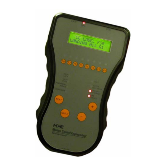
Page 147: F4: Messages And Floor Labels
F4: Messages and Floor Labels F4: Messages and Floor Labels The Messages and Floor Labels menu is used to program the CE FUNCTION SWITCHES F8 F7 F6 F5 F4 F3 F2 F1 fixture displays. To access, move the F4 switch to the up position. Messages and Floor Labels This display changes to: * MESSAGES AND *... - Page 148 The Computer Initialize all Labels DEFAULT LABELS [S] - Yes [N] - No. Use this function to initial- ize all labels to factory defaults.If you do not wish to complete the command, press and hold -, then press N to exit. Figure 5.2 PI Entry Procedure * MESSAGES AND * * FLOOR LABELS *...
-
Page 149: F5: Controller Utilities/Monitoring And Reporting
F5: Controller Utilities/Monitoring and Reporting F5: Controller Utilities/Monitoring and Reporting Place the F5 switch in the Up position (all others down). This FUNCTION SWITCHES F8 F7 F6 F5 F4 F3 F2 F1 option provides access to the Controller Utilities Menu and the Monitoring and Reporting Menu. -
Page 150: Date/Time
The Computer Date/Time Use to display and/or set the date and time (see Figure 5.3). VIEW - DATE AND TIME- To view the date and time: 1. Press N until View Date and Time is displayed, then press TIME: 02:35:10 S. -
Page 151: View Event Log
F5: Controller Utilities/Monitoring and Reporting View Event Log The event log tracks the most recent system events; each with date and time stamp. Event “01” is the most recent event, with older events numbered “02” through “99” respectively. 1. Press S to view the event log. An event number and the associated event (usually scrolling due to message length) are displayed on the top line of the display. -
Page 152: Clear Event Log
The Computer Clear Event Log This allows you to clear the events from the event log. 1. Press S push button to select Clear Event Log. A prompt appears: 2. Press S push button to clear the event log. A message appears notifying you that all events have been cleared. -
Page 153: Edg Diagnostics
F5: Controller Utilities/Monitoring and Reporting EDG Diagnostics Please see “CTL Diagnostic Menu” on page 5-72 for use instructions. Table 5.13 LS-EDGE Diagnostics Address Floor number Diagnostic Sensor Flags Encoder Pair 1 Encoder Pair 1 Encoder Pair 1 Encoder Pair 1 Main Encoder Measured Correction in Counts ETS Velocity... - Page 154 The Computer Table 5.13 LS-EDGE Diagnostics Address Floor number Diagnostic Measured magnet length in counts Floor height in counts DLM edge in counts ULM_edge in counts Front Floor 7 Floor height (inch or mm) Measured magnet length in counts Floor height in counts DLM edge in counts ULM_edge in counts Front Floor 8...
- Page 155 F5: Controller Utilities/Monitoring and Reporting Table 5.13 LS-EDGE Diagnostics Address Floor number Diagnostic Floor height in counts DLM edge in counts ULM_edge in counts Front Floor 14 Floor height (inch or mm) Measured magnet length in counts Floor height in counts DLM edge in counts ULM_edge in counts Front Floor 15...
- Page 156 The Computer Table 5.13 LS-EDGE Diagnostics Address Floor number Diagnostic Rear Floor 4 Floor height (inch or mm) Measured magnet length in counts Floor height in counts DLM edge in counts ULM_edge in counts Rear Floor 5 Floor height (inch or mm) Measured magnet length in counts Floor height in counts DLM edge in counts...
- Page 157 F5: Controller Utilities/Monitoring and Reporting Table 5.13 LS-EDGE Diagnostics Address Floor number Diagnostic Measured magnet length in counts Floor height in counts DLM edge in counts ULM_edge in counts Rear Floor 12 Floor height (inch or mm) Measured magnet length in counts Floor height in counts DLM edge in counts ULM_edge in counts...
-
Page 158: Ctl A Diagnostics
The Computer CTL A Diagnostics Please see “CTL Diagnostic Menu” on page 5-72 for use instructions. Table 5.14 Controller Board CTL A Processor Diagnostics Address Item Notes Front openings Rear openings Floors Bottom floor Top floor Bottom landing Top landing Bottom position Top position Raw position... - Page 159 F5: Controller Utilities/Monitoring and Reporting Table 5.14 Controller Board CTL A Processor Diagnostics Address Item Notes Speed @ UNTS2 over-speed fault Speed @ UNTS3 over-speed fault Speed @ UNTS4 over-speed fault Speed @ UNTS5 over-speed fault Runtime distance @ DETS Runtime distance @ DNTS1 Runtime distance @ DNTS2 Runtime distance @ DNTS3...
- Page 160 The Computer Table 5.14 Controller Board CTL A Processor Diagnostics Address Item Notes Floor zone Position bypass count Position pass count System position count Absolute position count Position lower sequence Position upper sequence Position lower value Position upper value Landing code At landing Near floor Port A inputs:...
- Page 161 F5: Controller Utilities/Monitoring and Reporting Table 5.14 Controller Board CTL A Processor Diagnostics Address Item Notes Port C inputs: 01 = (n/a) 02 = PHE 03 = MCSB 04 = MGBR 05 = FRSA 06 = (n/a) 07 = (n/a) 08 = (n/a) 09 = (n/a) 10 = (n/a)
- Page 162 The Computer Table 5.14 Controller Board CTL A Processor Diagnostics Address Item Notes Port F inputs: 01 = (n/a) 02 = (n/a) 03 = SPD0A 04 = SPD1A 05 = SPD2A 06 = (n/a) 07 = (n/a) 08 = (n/a) 09 = (n/a) 10 = (n/a) 11 = (n/a)
- Page 163 F5: Controller Utilities/Monitoring and Reporting Table 5.14 Controller Board CTL A Processor Diagnostics Address Item Notes Port C outputs: 01 = (n/a) 02 = (n/a) 03 = (n/a) 04 = (n/a) 05 = (n/a) 06 = (n/a) 07 = (n/a) 08 = (n/a) 09 = (n/a) 10 = (n/a)
- Page 164 The Computer Table 5.14 Controller Board CTL A Processor Diagnostics Address Item Notes Faults (01 - 16): 01 = Maximum position offset fault 02 = Minimum position offset fault 03 = Landing system communication loss fault 04 = Excessive faults shutdown 05 = FCL-1 is offline 06 = FCL-2 is offline 07 = Landing system ETS fault...
- Page 165 F5: Controller Utilities/Monitoring and Reporting Table 5.14 Controller Board CTL A Processor Diagnostics Address Item Notes 16 = BRE (MPI-A) 15 = DRE (MPI-A) 14 = PME (MPI-A) 13 = DRE (MPI-C) 12 = BRE (MPI-C) 11 = PME (MPI-C) 10 = (n/a) 09 = (n/a) 08 = (n/a)
- Page 166 The Computer Table 5.14 Controller Board CTL A Processor Diagnostics Address Item Notes 16 = UETS status 15 = UTS1 status 14 = UNTS2 status 13 = UNTS3 status 12 = UNTS4 status 11 = UNTS5 status 10 = DETS status 09 = DTS1 status 08 = DNTS2 status 07 = DNTS3 status...
- Page 167 F5: Controller Utilities/Monitoring and Reporting Table 5.14 Controller Board CTL A Processor Diagnostics Address Item Notes Up distance @ 30% of contract speed Up distance @ 20% of contract speed Up distance @ 10% of contract speed Upper position Lower position Median position Offset distance Software ID...
-
Page 168: Ctl B Diagnostics
The Computer CTL B Diagnostics Please see “CTL Diagnostic Menu” on page 5-72 for use instructions. Table 5.15 Controller Board CTL B Processor Diagnostics Address Item Notes Front openings Rear openings Floors Bottom floor Top floor Bottom landing Top landing Bottom position Top position Raw position... - Page 169 F5: Controller Utilities/Monitoring and Reporting Table 5.15 Controller Board CTL B Processor Diagnostics Address Item Notes Speed @ UNTS2 over-speed fault Speed @ UNTS3 over-speed fault Speed @ UNTS4 over-speed fault Speed @ UNTS5 over-speed fault Runtime distance @ DETS Runtime distance @ DNTS1 Runtime distance @ DNTS2 Runtime distance @ DNTS3...
- Page 170 The Computer Table 5.15 Controller Board CTL B Processor Diagnostics Address Item Notes Floor zone Position bypass count Position pass count System position count Absolute position count Position lower sequence Position upper sequence Position lower value Position upper value Landing code At landing Near floor Port A inputs:...
- Page 171 F5: Controller Utilities/Monitoring and Reporting Table 5.15 Controller Board CTL B Processor Diagnostics Address Item Notes Port C inputs: 01 = (n/a) 02 = MSAFL1 03 = MDZLV 04 = MABGF 05 = GS 06 = (n/a) 07 = (n/a) 08 = (n/a) 09 = (n/a) 10 = (n/a)
- Page 172 The Computer Table 5.15 Controller Board CTL B Processor Diagnostics Address Item Notes Port A outputs: (n/a) Port B outputs: (n/a) Port C outputs: 01 = (n/a) 02 = (n/a) 03 = (n/a) 04 = (n/a) 05 = (n/a) 06 = (n/a) 07 = (n/a) 08 = (n/a) 09 = (n/a)
- Page 173 F5: Controller Utilities/Monitoring and Reporting Table 5.15 Controller Board CTL B Processor Diagnostics Address Item Notes Port G outputs: 01 = (n/a) 02 = (n/a) 03 = (n/a) 04 = (n/a) 05 = (n/a) 06 = (n/a) 07 = (n/a) 08 = (n/a) 09 = (n/a) 10 = (n/a)
- Page 174 The Computer Table 5.15 Controller Board CTL B Processor Diagnostics Address Item Notes Faults (33 - 48): 01 = (n/a) 02 = (n/a) 03 = (n/a) 04 = (n/a) 05 = (n/a) 06 = (n/a) 07 = (n/a) 08 = (n/a) 09 = (n/a) 10 = (n/a) 11 = (n/a)
- Page 175 F5: Controller Utilities/Monitoring and Reporting Table 5.15 Controller Board CTL B Processor Diagnostics Address Item Notes 16 = (n/a) 15 = (n/a) 14 = (n/a) 13 = (n/a) 12 = (n/a) 11 = (n/a) 10 = Up slowdown 09 = Down slowdown 08 = Near top 07 = Near bottom 06 = Up direction limit...
- Page 176 The Computer Table 5.15 Controller Board CTL B Processor Diagnostics Address Item Notes Up distance @ 30% of contract speed Up distance @ 20% of contract speed Up distance @ 10% of contract speed Upper position Lower position Median position Offset distance Software ID Software Revision...
-
Page 177: System Can Bus
F5: Controller Utilities/Monitoring and Reporting System CAN Bus The System CAN Bus/Data Viewing screen allows you to check the working status of the inputs and outputs of any Car Panel Interface board in the system. • Press S to enter the menu Byte 0 CAN Data Bytes in Hex Byte 7... -
Page 178: Monitoring And Reporting Menu
The Computer Monitoring and Reporting Menu If the controller is configured for monitoring or reporting con- *MONITORING AND* nections through Ethernet, this menu is used to set up the port *REPORTING MENU* and to view communication statistics for diagnostic purposes. If Monitoring and Reporting Menu is not displayed, press N push button. - Page 179 F5: Controller Utilities/Monitoring and Reporting • The XPort Comm Resets screen indicates the number of XPort<>PIC COMM: times the port has been reset since the last HC-CHP reset. COMM RESETS:1 If it exceeds three, you may have a network problem. •...
-
Page 180: F6: Hoistway Learn Operations
The Computer F6: Hoistway Learn Operations The F6 menu provides a process to learn the floor levels and counterweight position for the building. The process is different depending on the type of landing/positioning system for the job. LS-EDGE Steel Tape Please refer to “Hoistway Learn, LS-EDGE”... -
Page 181: F7: Parameters Adjust
F7: Parameters Adjust F7: Parameters Adjust Through the F7 menu, you can fill and/or adjust motion related parameters. With the car on Inspection and the F7 function switch in the UP position, the N button is used to cycle between the two (Fill or Adjust) menus. -
Page 182: Using Id Numbers For Direct Parameter Access
The Computer Using ID Numbers for Direct Parameter Access All F7 parameters have a fixed ID number. When you are in the F7 menu, you can scroll to a particular ID by: • Press and hold N (Next) to increment to the desired ID. •... - Page 183 F7: Parameters Adjust Table 5.17 F7 Parameters Item Default Notes Landing System LS-EDGE LS-EDGE should be selected. Stepping System Single Dual Dual Single or dual stepping per floor. Step down into floor when car is Step Dn1 0.xx inches 20 inches 96 inches more than one floor away Step up into floor when car is...
-
Page 184: Parameters
The Computer Parameters Floor Heights Parameters 1 through 32 represent floor heights within the building. Floor heights are stored as absolute values referenced to the first floor, which is always initially displayed as 0.0 inches. You have already learned all floor heights in the building (F6), so they will be displayed as you progress. - Page 185 F7: Parameters Adjust Stepping System, 208 [SINGLE or DUAL]. Set to Dual if both stepping and sub-step- ping are used. Set to single if only stepping is used. • SINGLE - - If this option is selected, only STEP UP / STEP DN parameters will be visible and adjustable by the user.
-
Page 186: F8: Status Displays
The Computer F8: Status Displays Displays various system statuses. To view the Status Displays: FUNCTION SWITCHES F8 F7 F6 F5 F4 F3 F2 F1 1. Place function switch F8 in the up position (all others down). 2. Press N to cycle through available status displays. Status Displays The following status displays are available: •... -
Page 187: F1 & F8: Board Software Versions
F1 & F8: Board Software Versions F1 & F8: Board Software Versions When both F1 and F8 switches are up, board software version numbers are visible. This can be helpful when troubleshooting with an MCE technician. • Press N button for versions: •... -
Page 188: Duplexing
The Computer Duplexing A great advantage of the Motion 2000 is how easily it can be duplexed. Because the duplexing logic is completely internal to the computers, it requires only a connecting cable and the selec- tion of the Duplex option (see “SIMPLEX / LOCAL OR DUPLEX?”... -
Page 189: In This Section
• In This Section • Troubleshooting Tools • Status and Error Messages • PC Board Quick References • MLT/VLT Data Trap Troubleshooting In This Section This section contains general troubleshooting related information and tabled information to help you diagnose and correct problems. If you are viewing this on a computer, click the page number to jump to the appropriate section. -
Page 190: Troubleshooting Tools
Please refer to “ICE-COP-2 Car Panel Interface Board” on page 6-60. • Motion 2000 Parameter Settings Record: This table in the Appendix provides a record of the original parameter settings as well as a place to record changes made to the parameters. -
Page 191: Status And Error Messages
Status and Error Messages Status and Error Messages While in Diagnostic Mode, the top line of the LCD display shows CAR IN TEST MODE the prevailing status of the elevator. The message is scrolled. PI 8 2O:1O11OO11 There is a status message for each special operation (e.g., FIRE SERVICE PHASE 1 - MAIN). - Page 192 Troubleshooting Table 6.1 Status and Error Messages Scrolling Message - Special Event Message 2 BUS IS LOW Description: 2 bus (120VAC) monitoring input is low. Troubleshooting: 1. Check 2 bus fuses. 2FS BUS IS LOW Description: 2FS bus (120VAC) monitoring input is low. Troubleshooting: 1.
- Page 193 Status and Error Messages Table 6.1 Status and Error Messages Scrolling Message - Special Event Message AUXILIARY STARTER TIMEOUT Description: One of the auxiliary starters did not start properly. Troubleshooting: On a solid state starter, the DR1 input did not go high within the time pro- grammed in the UP TO SPEED TIMER parameter (1.0 - 8.0 sec).
- Page 194 Troubleshooting Table 6.1 Status and Error Messages Scrolling Message - Special Event Message CAR CALL BUS IS DISCONNECTED Description: Usually indicates a problem in the wiring or fuses. There is no power to the Car Call circuits. Troubleshooting: Check the Car Call Bus fuse. Check the wires that go to the Car Call Power inputs in the controller.
- Page 195 Status and Error Messages Table 6.1 Status and Error Messages Scrolling Message - Special Event Message CTL A MPU A IS OFFLINE Description: CPU-A on HC-MPU board is not responding. Troubleshooting: 1. Verify that CPU-A ON LED on the HC-MPU board is on solid and not flashing. 2.
- Page 196 Troubleshooting Table 6.1 Status and Error Messages Scrolling Message - Special Event Message CTL A or B LANDING SYSTEM COMM LOSS Description: The HC-CTL2 board is not communicating with the landing system properly (A or B channel lost). Before beginning troubleshooting, check all related CAN connections and connectors carefully.
- Page 197 Status and Error Messages Table 6.1 Status and Error Messages Scrolling Message - Special Event Message CTL A or B LANDING SYSTEM FLOOR MISMATCH (FLOOR LEARN REQUIRED) Description: The landing system floor heights were not learned with the current controller and landing system configuration.This fault can occur if the HC-CTL-2 board or landing system is replaced.
- Page 198 Troubleshooting Table 6.1 Status and Error Messages Scrolling Message - Special Event Message DOL INPUT FAILURE (CTLB) Description: The Door Open Limit (DOL) input is not in the correct state for the position of the door as determined by the Door Position Monitor (DPM) input and the Gate Switch (GS) input. Troubleshooting: 1.
- Page 199 Status and Error Messages Table 6.1 Status and Error Messages Scrolling Message - Special Event Message DOWN TERMINAL LIMIT FAILURE (Hydro only) Description: Both the Down Slow Limit and Down Emergency Limit switches have been detected to be in opposite states. These switches should open/close simultaneously, meaning that the volt- age at these terminals should always be identical.
- Page 200 Troubleshooting Table 6.1 Status and Error Messages Scrolling Message - Special Event Message DVR 1 IS OFFLINE (CTLA) (Hydro only) Description: Driver board HC-DVR #1 is offline. Troubleshooting: 1. Power to the HC-DVR board may not be connected. Check the CAN bus connection between the HC-DVR board and the HC-CHP CAN hub and power distribution board.
- Page 201 Status and Error Messages Table 6.1 Status and Error Messages Scrolling Message - Special Event Message DVR-’n’ AUXILIARY STARTER TIMEOUT (n = 2 or 3) (Hydro only) Description: One of the auxiliary starters did not start properly. Troubleshooting: On a solid state starter, the DR1 input did not go high within the time pro- grammed in the UP TO SPEED TIMER parameter (1.0 - 8.0 sec).
- Page 202 Troubleshooting Table 6.1 Status and Error Messages Scrolling Message - Special Event Message DVR-’n’ MDFE FAILED TO ACTIVATE (n = 2 or 3) (Hydro only) Description: The MDFE input monitors the status of the DFE triac and the DFE triac driver. When either fails to activate when expected this fault is generated.
- Page 203 Status and Error Messages Table 6.1 Status and Error Messages Scrolling Message - Special Event Message DVR-’n’ MSSD FAILED TO DEACTIVATE (n = 2 or 3) (Hydro only) Description: MSSD monitors the solid state output of U1 and driver TY for proper operation If either fail in the on position this fault is generated.
- Page 204 Troubleshooting Table 6.1 Status and Error Messages Scrolling Message - Special Event Message DVR-’n’ MUFE FAILED TO ACTIVATE (n = 2 or 3) (Hydro only) Description: The MUFE input monitors the status of the UFE triac and the UFE triac driver. When either fails to activate when expected this fault is generated.
- Page 205 Status and Error Messages Table 6.1 Status and Error Messages Scrolling Message - Special Event Message DVR-’n’ OLM INPUT IS LOW (n = 2 or 3) (Hydro only) Description: The OLM input monitors the status of the both the thermal overload and the starter overload contacts.
- Page 206 Troubleshooting Table 6.1 Status and Error Messages Scrolling Message - Special Event Message EARTHQUAKE OPERATION Description: The EQI and/or CWI input is/are active. The car is on earthquake operation. Troubleshooting: If there has been no seismic activity, check the status of the EQI and CWI inputs.
- Page 207 Status and Error Messages Table 6.1 Status and Error Messages Scrolling Message - Special Event Message FIRE SERVICE PHASE 1 - ALTERNATE Description: The car is returning to an alternate fire return landing. The FRS input is low, the FRA input is high or FRAON is active.
- Page 208 Troubleshooting Table 6.1 Status and Error Messages Scrolling Message - Special Event Message GROUP TO CAR COMMUNICATION LOSS Description: The car controller has detected a loss of communication with the group controller. Troubleshooting: 1. Verify that the group controller’s MC-MCP board is operating. 2.
- Page 209 Status and Error Messages Table 6.1 Status and Error Messages Scrolling Message - Special Event Message HOSPITAL PHASE 2 OPERATION Description: The car has answered a hospital emergency call or the in car hospital emergency key switch has been activated (HOSP is high). Troubleshooting: Ensure that the hospital emergency operation option is set correctly.
- Page 210 Description: The car is on Inspection operation. Troubleshooting: Check all of the inspection switches and associated wiring. LANDING SYSTEM REDUNDANCY FAILURE (Non ASME-2000) Description: Either DZ, LU or LD has failed closed. Troubleshooting: Ensure that on any run between floors, the LSR input goes low at least once. If the DZ sensor has failed closed, power will be present continuously on the LSR input.
- Page 211 Status and Error Messages Table 6.1 Status and Error Messages Scrolling Message - Special Event Message LEVELING SENSOR FAILURE Description: One or both of the LU and LD sensors have failed closed. Troubleshooting: Ensure that power is not present on both the LU and LD inputs. LEVELING UP Description: The Level Up computer input is ON.
- Page 212 Troubleshooting Table 6.1 Status and Error Messages Scrolling Message - Special Event Message MABGF INPUT FAILURE (CTLB) Description: The Front Access Gate Bypass Monitor (MABGF) input has detected a failure of the Access Bypass Gate A (ABGA) or Front Access Bypass Bottom (FABB) outputs. Troubleshooting: 1.
- Page 213 Status and Error Messages Table 6.1 Status and Error Messages Scrolling Message - Special Event Message MDFE FAILED TO ACTIVATE (Hydro only) Description: The MDFE input monitors the status of the DFE triac and the DFE triac driver. When either fails to activate when expected this fault is generated. When the doors are locked, the 2L bus is high, DSL1 and DSL2 limits are closed, the down normal limit (DNTD) is closed and the car is idle, terminals DF and DFE should 120VAC.
- Page 214 Troubleshooting Table 6.1 Status and Error Messages Scrolling Message - Special Event Message MDZLV INPUT FAILURE (CTLB) Description: The Door Zone/Leveling Monitor (MDZLV) input has detected a failure of the Door Zone/Leveling (DZLV) or (DZLVA) outputs or failure of the normally open DZ relay. Troubleshooting: 1.
- Page 215 Status and Error Messages Table 6.1 Status and Error Messages Scrolling Message - Special Event Message MHDBR INPUT FAILURE (RDRB) Description: The Rear Hoistway Door Bypass Monitor (MHDBR) input has detected a failure of the Rear Hoistway Door Bypass (HDBR) or (HDBBR) outputs. Troubleshooting: 1.
- Page 216 Troubleshooting Table 6.1 Status and Error Messages Scrolling Message - Special Event Message MSSD FAILED ACTIVE (CTLB) Description: MSSD monitors the solid state output of U1 and driver TY for proper operation If either fail in the on position this fault is generated. Troubleshooting: 1.
- Page 217 Status and Error Messages Table 6.1 Status and Error Messages Scrolling Message - Special Event Message MTD INPUT FAILURE (CTLA) (Hydro only) Description: The input monitors the continuity of the DEL contactor coil and also checks the OFF state of the (TD) triac. Troubleshooting: 1.
- Page 218 Troubleshooting Table 6.1 Status and Error Messages Scrolling Message - Special Event Message MTY INPUT FAILURE (Hydro only) Description: The input monitors the continuity of the Y Contactor coil and also checks the OFF state of the (TY) triac. Troubleshooting: 1.
- Page 219 Status and Error Messages Table 6.1 Status and Error Messages Scrolling Message - Special Event Message MUSE INPUT IS LOW (CTLA) (Hydro only) Description: The MUSE input monitors the continuity of the Up Slow Valve coil and also checks the OFF state of the USE triac.
- Page 220 Troubleshooting Table 6.1 Status and Error Messages Scrolling Message - Special Event Message PRESSURE SWITCH ACTIVATED Description: This message is displayed when the Pressure Switch Input (PSS) is programmed and activated (low). Troubleshooting: Check the associated hardware device and take appropriate action. R2L INPUT FAILURE (CTLA) Description: The R2L input monitors the state of the 2L relay.
- Page 221 RDLS or RDLSR inputs. If power is present, one or more of the door lock relays has failed in the closed or picked position. REDUNDANCY FRONT GATE SWITCH FAILURE (Non ASME-2000) Description: The car gate switch relay has failed closed.
- Page 222 Troubleshooting Table 6.1 Status and Error Messages Scrolling Message - Special Event Message RSV INPUT FAILED TO ACTIVATE (CTLA) (Hydro only) Description: With the VALVE TYPE parameter set to PILOT RELAYS, the Redundancy Slow Valves (RSV) input did not go high when controller deactivated the associated pilot relays. Troubleshooting: 1.
- Page 223 Status and Error Messages Table 6.1 Status and Error Messages Scrolling Message - Special Event Message SPB IS OFFLINE (CTLA) Description: Safety processor B on the HC-CTL board is offline. Troubleshooting: 1. Power to the HC-CTL board may not be connected. Check the CAN bus connection between the HC-CTL board and the HC-CHP CAN hub and board.
- Page 224 Troubleshooting Table 6.1 Status and Error Messages Scrolling Message - Special Event Message UP TERMINAL LIMIT FAILURE Description: Both the Up Slow Limit and Up Emergency Limit switches have been detected to be in opposite states. These switches should open/close simultaneously, meaning that the voltage at these terminals should always be identical.
-
Page 225: Pc Board Quick References
PC Board Quick References PC Board Quick References This section contains information about Motion 2000 circuit boards including photographs with informational call outs, input/outputs, indicators, jumpers, test points and other informa- tion pertinent to troubleshooting. The circuit boards are listed in the table below. If you are viewing this file on a computer, click the page number to jump to the appropriate section. -
Page 226: Hc-Chp Can Hub And Power Supply Board
Troubleshooting HC-CHP CAN Hub and Power Supply Board This board provides 5-volt, 4-amp DC power for digital integrated circuits throughout the con- troller. It also provides a central connection point for the Controller Area Network (CAN).i Figure 6.1 HC-CHP CAN Hub and Power Supply Board M1:Optional Ethernet connection J16, J17 External Network connections... -
Page 227: Sw1 Dip Switch Settings
• CPU ON: LED on indicates that the on-board microcontroller is functional. Switches • SW1: DIP switches (see SW1 DIP Switch Settings below). • RST: microcontroller reset button. Figure 6.2 Upgrading Motion 2000 Firmware J16, J17, External Network connections SW1 Switches Update firmware using EEPROMs... -
Page 228: Hc-Ctl Control Board
Troubleshooting HC-CTL Control Board The HC-CTL-2 Control board monitors I/O, performs safety functions and provides front and rear door operation. The HC-CTL-2 board is responsible for Inspection, Fire Service, Landing System, door lock bypass, lanterns, and gongs. Figure 6.3 HC-CTL-2 Control Board 6-40 Manual # 42-02-1P21... -
Page 229: Hc-Ctl-2 Terminal Definitions
PC Board Quick References HC-CTL-2 Terminal Definitions Table 6.3 HC-CTL-2 Board Terminals Connector Terminal Description Board programming, factory only Board programming, factory only Board programming, factory only CAN bus connection from HC-CHP board Not used for traction control Not used for traction control Not used for traction control Not used for traction control BAB1... - Page 230 Troubleshooting Table 6.3 HC-CTL-2 Board Terminals Connector Terminal Description ICTD See description, connector J27 MCE wired ICTU See description, connector J27 at factory. CTEN See description, connector J27 Not for field INCT See description, connector J27 connection. See description, connector J27 See description, connector J27 See description, connector J27 MCE wired...
- Page 231 PC Board Quick References Table 6.3 HC-CTL-2 Board Terminals Connector Terminal Description Ground MCE wired DCOM Digital Common at factory. 120 VAC Not for field Provides 120VAC to 2L bus when SAFL and SAFS relays are picked (input). connection. Provides 120VAC to valves and motor signals when doors are locked and safety string is made up (Output).
-
Page 232: Hc-Ctl-2 Board Led Indicators
Troubleshooting Table 6.3 HC-CTL-2 Board Terminals Connector Terminal Description FRSA Fire Service Alternate Initiating Device, machine room (input) FRSM Fire Service Main Initiating Device, all other hoistway fire service initiating devices (input) FRES Fire Service Reset (input) Main Landing Smoke Sensor (input) Smoke/Fire Sensors for all landing that are not main (input) INCT Car Top Inspection... -
Page 233: Hc-Ctl-2 Board Jumpers, Fuses, Testpoints, And Switches
PC Board Quick References HC-CTL-2 Board Jumpers, Fuses, Testpoints, and Switches Table 6.4 HC-CTL-2 Board Jumpers Jumper Description IC U2 program source, factory use only. Default is No Jumper. Fault Bypass, 2 position. A = Bypass active; B = Bypass off. B position is default. Table 6.5 HC-CTL-2 Board Fuses Fuse Description... - Page 234 Troubleshooting Table 6.6 HC-CTL-2 Board Test Points Test Point Description TP26 MGBR, monitors status of car door bypass switch, rear door, pole 1, high = bypass off TP27 MHDB, monitors status of hoistway door bypass switch, pole 4, high = bypass off TP28 MHDBR, monitors status of hoistway door bypass switch, pole 1, high = bypass off TP29...
-
Page 235: Hc-Dvr Driver Board
PC Board Quick References HC-DVR Driver Board The HC-DVR Driver board(s) control the pump(s) and valves. Figure 6.4 HC-DVR Driver Board J2: Internal CAN connection TP MR1 TP DR1 TP +5V TP YR1 Indicators SW2: RST TP GND TP M1 TP DD1 TP YD1 Switches... - Page 236 Troubleshooting Table 6.9 HC-DVR Board Terminals Connector Terminal Description Used to program the U15 microcontroller Internal CAN signal and power 2L bus output 2l bus output Connects to input of thermal overload (Also monitors 2L bus) Connects to output of thermal overload UNTD Up normal limit (input) Up slow (Provides power to valve, output)
- Page 237 PC Board Quick References Table 6.9 HC-DVR Board Terminals Connector Terminal Description MCE valve connections (See J3) MCE valve connections (See J3) MCE valve connections (See J3) MCE valve connections (See J3) MCE valve connections (See J3) MCE limits connections (See J3) MCE limits connections (See J3) USL2 MCE limits connections (See J3)
-
Page 238: Hc-Mpu Main Processor Board
Troubleshooting HC-MPU Main Processor Board The HC-MPU board performs control data processing and is responsible for: • Car operation • Car communication • Programming and diagnostics • Redundancy cycle testing • System software validation • Duplexing Figure 6.5 HC-MPU Main Processor Unit Board J6: CPU B Debug M1: Ethernet Port A LCD Display... - Page 239 PC Board Quick References Table 6.12 HC-MPU Board Switches Switches Description RSTA: Reset CPU A RSTB: Reset CPU B “-” minus push button “S” push button “+” plus push button “N” push button Port Selection: RS232 Port A / Ethernet Port A DIP Function switches F5 through F8 DIP Function switches F1 though F4 Table 6.13 HC-MPU Board Indicators...
-
Page 240: Hc-Mpu Battery
Troubleshooting Table 6.15 HC-MPU Board Terminals Connector Description Used to program CPU A. IDC connector. Keyboard Port. Six pin DIN connector. RS-232 Port A. Nine pin D-sub connector. External CAN Port. Three pin Weidmuller connector (CAN H, CAN L, SHLD). Signal for CAN connections outside the controller cabinet. -
Page 241: Hc-Uio-2 Universal Input/Output Board
PC Board Quick References HC-UIO-2 Universal Input/Output Board Depending upon the software installed, HC-UIO boards may be used for programmable inputs and outputs (16 per board), car and hall calls, door operator interface, or dispatching. In addi- tion to being backwards compatible with the HC-UIO board, the HC-UIO-2 also contains the following enhancements: 1. - Page 242 Troubleshooting Figure 6.7 Typical Input and Output Connection (Board ID 0 to 15) When using a board con- Power Supply nection in IO mode, con- PS1 and PS2 are used nect the associated PS to provide input pull-up input to the same voltage ONLY when I/O Jumpers are set to I/O used to power the fix-...
-
Page 243: Switches
PC Board Quick References Switches Switches are ONLY checked by the board processor on start-up. Press the processor RESET button after any change to switches. • DIP SW2: • Switches 1 through 6 = Board ID • Switches 7 & 8 = Baud rate •... -
Page 244: Hc-Uio-2 Switches 7, 8 And 9 Settings
Troubleshooting HC-UIO-2 Switches 7, 8 and 9 Settings On the HC-UIO-2 Board switches 7 and 8 set the baud rate at which the CAN bus communicates with this board. Table 6.17 HC-UIO-2 Board Switches 7 and 8 Sw 7 Sw 8 Baud Rate Description 500 kbps... -
Page 245: Troubleshooting
PC Board Quick References Troubleshooting • I/O LED is Blinking: • Low impedance or largely reactive load (in-rush current surge >3A or steady state >300mA) • Output connected to line source with no series load • Input board addressed as output board (switches are only checked on boot up; reset processor after any switch change) •... -
Page 246: Call Inputs And Outputs
Troubleshooting Call Inputs and Outputs Table 6.20 HC-UIO-2 Board Call Assignments Board Switch Setting IO 1 to IO 16 Off Off Off Off Off Off HC-UIO-2 boards numbered 00 through 31 are used for call related IO. On Off Off Off Off Off The associated switch setting is shown to the left. -
Page 247: Spare Inputs And Outputs
PC Board Quick References Spare Inputs and Outputs The first ten Spare Inputs (SP1 through SP10) are assigned to terminals SPIN1 through SPIN10 on the HC-CTL board (connectors J6 and J10). The first four Spare Outputs (OUT1 through OUT4) are assigned to terminals 1 through 4 (J15) on the HC-CTL board. The remainder of the Spare Inputs and Outputs are assigned to HC-UIO-2 boards numbered 32 through 36 as shown in the table below. -
Page 248: Ice-Cop-2 Car Panel Interface Board
Troubleshooting ICE-COP-2 Car Panel Interface Board The ICE-COP-2 board, mounted in the car operating panel, converts the discrete closures from the panel buttons and switches to data on the CAN serial bus and passes it through the MC-LSI Landing System Interface board on the cartop, up the traveler to the car controller. Additional ICE-COP-2 boards are used to accommodate rear doors or installations with many floors, COP buttons, and lamps. -
Page 249: Ice-Cop-2 Board Details
PC Board Quick References Normal Operation During normal operation, I/O LEDs will be lighted when the associated I/O is active (dimmer when the output is active; brighter when the input is active). The SPA processor LED will be continuously lighted. If I/O LEDs remain in a static condition or the SPA processor LED is not continuously on: •... - Page 250 Troubleshooting • Motion CAN Baud Rate • Switch 7 OFF: 250k (default) • Switch 7 ON: 500k • Motion Unused Switches • Switches 4 and 6 are unused and should be left in the OFF position. • 24V Power: The 24V power supply from the cartop box must be connected to the 24V IN connector J35 on the first ICE-COP-2 board.
- Page 251 PC Board Quick References Figure 6.10 ICE-COP-2 Serial Car Operating Panel Board 4-pin “universal” inputs may be used instead of screw terminals if desired. Test points,+5v Not used for Motion controllers Reset button 8-position DIP switch package SPA processor OK connections 24 VDC 6W max.
-
Page 252: Mc-Cpi Car Panel Interface Board
Troubleshooting MC-CPI Car Panel Interface Board The MC-CPI board, mounted in the car operating panel, converts the discrete closures from the panel buttons and switches to data on the CAN serial bus and passes it through the MC-LSI Landing System Interface board on the cartop, up the traveler to the car controller. Additional MC-CPI boards are used to accommodate rear doors or installations with many floors, COP but- tons, and lamps. - Page 253 PC Board Quick References Figure 7. MC-CPI Serial Car Panel Interface Board I/O only 24 VDC max. Inputs only 6W max. 24 VDC max. 6W max. SW1 Board Address Reset button Outputs only SPA ON indicator 24 VDC max. 6W max. From Power Supply - J5 +24VDC...
-
Page 254: Mc-Cpi Board Details
Troubleshooting MC-CPI Board Details • 24V Inputs Only: Typical circuit for terminals I1 through I16. • 24V Outputs Only: Typical circuit for terminals O1 through O16 • 24V Inputs/Outputs Only: Typical circuit for terminals IO1 through IO16. Call Button / Lamp •... - Page 255 PC Board Quick References Figure 6.1 Example: MC-CPI Wiring 6-67...
-
Page 256: Before Applying Power
Troubleshooting Before Applying Power Prior to applying power to the MC-CPI board(s): 1. Disconnect all terminal connectors from the MC-CPI boards (I/O connections, internal network and power connections (24V and COM terminals). 2. Apply power to the system. 3. Using a multimeter, check each of the wires to be connected to the MC-CPI boards as follows: •... -
Page 257: Mc-Lsi Landing System Interface Board
LSI board provides power to the landing system and to any Universal I/O boards that might be used on the cartop through the CAN connections to those components. A shielded, external CAN connection runs from the LSI board, through the traveler, to the Motion 2000 controller. -
Page 258: Sc-3Hn Three Input Serial Hall Call Node Board
Troubleshooting SC-3HN Three Input Serial Hall Call Node Board The SC-3HN board is used to provide serial hall calls for Motion systems. The SC-3HN provides analog inputs and outputs for the hall call buttons and LEDs and a CAN connection to the group or controller. - Page 259 PC Board Quick References Figure 6.4 Hall Call Node Wiring +24 V CAN H CAN L UL - UL + UP HALL CALL (Others similar) Table 6.22 Hall Wiring Colors Color Signal +24V black common brown CAN H yellow CAN L orange blue violet...
-
Page 260: Addressing And Can Bus Termination
Troubleshooting Addressing and CAN Bus Termination Set SC-3HN addresses as shown in the job prints for the installation. Generic examples are pro- vided below. Riser Assignment There may be up to four Main risers and four Auxiliary risers. Jumper locations JP3, JP2, and JP1 are used to assign the appropriate riser to the SC-3HN board. -
Page 261: On Board Diagnostics
PC Board Quick References On Board Diagnostics Two LEDs provide diagnostic information: The ON LED (green) and the FLT LED (red). ON LED The ON LED reflects power/communications status. • ON: Serial hall call bus to Group/Car OK • OFF: Board is not receiving power or has no software loaded. •... -
Page 262: Using The Mlt / Vlt Data Trap
Troubleshooting Using the MLT / VLT Data Trap The MLT / VLT “data trap” records many of the controller's operation “flags” at the moment the MLT or VLT occurs. This allows you to see what flags led up to the fault. Note: Direction must be on (input UPS) for the adjustable time set via parameter MOTOR LIMIT TIMER (1 - 6 min- utes) before MLT will occur. - Page 263 Using the MLT / VLT Data Trap PHC Hydro Data Trap Memory Chart Diagnostic Indicators Address DOLM 0480 On / Off On / Off On / Off On / Off On / Off On / Off On / Off On / Off 0481 On / Off On / Off...
- Page 264 Troubleshooting 6-76 Manual # 42-02-1P21...
-
Page 265: Section 7. Appendix
• Elevator Security Information • LS-QUTE Assembly Appendix In this Section • Motion 2000 Parameter Settings Record: Use this table to record the original parameter values and any changes made to these values (see page 7-2). • F7 Parameter Settings Record: Use this table to record the original parameter values... -
Page 266: Motion 2000 Parameter Settings Record
Appendix Motion 2000 Parameter Settings Record This form is provided for recording the current parameter settings on your Motion 2000 con- troller. If the firmware is upgraded or parameters are re-set to default values, you can then com- pare the parameter settings to this record to verify that they are correct. -
Page 267: Program Mode (F1) Parameter Settings Record
Motion 2000 Parameter Settings Record Program Mode (F1) Parameter Settings Record Program Mode (F1) Parameter Settings Record NEW VALUES OPTIONS CURRENT VALUES BASIC FEATURES Controller Type: ___ Hydro (M2000) ___ Traction (M4000) ___ Hydro (M2000) ___ Traction (M4000) Simplex / Local or Duplex? - Page 268 Appendix Program Mode (F1) Parameter Settings Record NEW VALUES OPTIONS CURRENT VALUES Leave Door Open on PTI/ESS? _____ Yes ______ No _____ Yes ______ No Nudging During Fire Phase 2? _____ Yes ______ No _____ Yes ______ No Dir. Preference Until DLK? _____ Yes ______ No _____ Yes...
- Page 269 Motion 2000 Parameter Settings Record Program Mode (F1) Parameter Settings Record NEW VALUES OPTIONS CURRENT VALUES SPARE INPUTS (SP1) SPIN1 on HC-CTL used for: (SP2) SPIN2 on HC-CTL used for: (SP3) SPIN3 on HC-CTL used for: (SP4) SPIN4 on HC-CTL used for:...
- Page 270 Appendix Program Mode (F1) Parameter Settings Record NEW VALUES OPTIONS CURRENT VALUES I15 on CPI F used for: I16 on CPI F used for: I10 on CPI R used for: I11 on CPI R used for: I12 on CPI R used for: I13 on CPI R used for: I14 on CPI R used for: I15 on CPI R used for:...
- Page 271 Motion 2000 Parameter Settings Record Program Mode (F1) Parameter Settings Record NEW VALUES OPTIONS CURRENT VALUES (OUT40) IO 12 on UIO 36 used for: (OUT41) IO 13 on UIO 36 used for: (OUT42) IO 14 on UIO 36 used for:...
- Page 272 _____ No (Traction only) First Lower/Run on EP Power _____ A _____ B _____ A _____ B ADDITIONAL CAR OPTIONS (Hydro only) (was ASME A17.1 - 2000 Features) Hoistway Access? _____ Yes _____ No _____ Yes _____ No Top Access?
- Page 273 Bottom Access? _____ Front _____ Rear _____ Front _____ Rear ADDITIONAL CAR OPTIONS (Hydro & Traction) (was ASME A17.1 - 2000 Features) Door Position Monitor ____ None ____Front ____ Rear ____Both ____ None ____Front ____ Rear _____Both Front Door Close Limit?
-
Page 274: F7 Parameter Settings Record
Appendix F7 Parameter Settings Record Please use the following table to record your F7 menu settings. If the HC-CTL-2 board is replaced in the future, this will provide you a quick way to re-enter proper settings. Also, if you place a support call to MCE, these values are information you will need to speed problems solv- ing.) Table 7.1 F7 Parameter Log Description... - Page 275 F7 Parameter Settings Record Table 7.1 F7 Parameter Log Description Setting 231 Step Dn12 232 Step Up12 233 Step Dn13 234 Step Up13 235 Step Dn14 236 Step Up14 237 Step Dn15 238 Step Up15 239 Step Dn16 240 Step Up16 241 Sub-Step Dn1 242 Sub-Step Up1 243 Sub-Step Dn2...
-
Page 276: Elevator Security Information And Operation
Appendix Elevator Security Information and Operation Building name: Building location: Security activation: Key switch Mon: from Tue: from Time clock Wed: from Thu: from Fri: from Sat: from Sun: from Instructions: To gain access to secured floors, follow the steps below while in the elevator car. The steps may be taken while the car is moving or standing still. -
Page 277: Security Codes
Elevator Security Information and Operation Security Codes Maintain a record of the security codes by noting the floor name as found in the elevator cab and each floor's code. Any floor with a security code is a secured floor. 1. Floor security code 2. -
Page 278: Ls-Qute Landing System Assembly Drawings
Appendix LS-QUTE Landing System Assembly Drawings Note If a sensor or the HC-IPLS board is replaced, make sure the orientation of the HC-IPLS board is correct. Use the chassis ground and the LEDs shown in the figure below for an orienta- tion reference. - Page 279 LS-QUTE Landing System Assembly Drawings Figure 7.2 LS-QUTE Wiring Diagram DZX is between DZ1 and DZ2 Hinged standoffs D/N: 1206 R3 SENSOR HC-IPLS BOARD TERMINALS DZ2 SENSOR SDZX DZ1 SENSOR SDZF SDZR ISTD ISTD ISTU ISTU One 2 inch jumper 7-15...
-
Page 280: Factory I/O Assignment, Ice-Cop-2 Boards
Appendix Factory I/O Assignment, ICE-COP-2 Boards COP-2 Board #1 - ID: 0 The first COP-2 board contains standard dedicated inputs as follows: FCCC FCHLD FCOFF The first COP-2 board contains standard dedicated outputs as follows: IO16 IO15 IO14 IO13 IO12 IO11 IO10 CGEU... -
Page 281: Cop-2 Board #3 - Id: 2
Factory I/O Assignment, ICE-COP-2 Boards COP-2 Board #3 - ID: 2 The third COP-2 board contains spare inputs as follows: SPIN SPIN SPIN SPIN SPIN SPIN SPIN The third COP-2 board contains spare outputs as follows: IO16 IO15 IO14 IO13 IO12 IO11 IO10... -
Page 282: Cop-2 Board #5 - Id: 5
Appendix COP-2 Board #5 - ID: 5 The fifth COP-2 board contains standard dedicated car calls (see note) as follows: 116R 115R 114R 113R 112R 111R 110R 109R IO16 IO15 IO14 IO13 IO12 IO11 IO10 124R 123R 122R 121R 120R 119R 118R 117R... - Page 283 API, Alternate Parking Input flag 5-9 final adjustments 4-7, 4-8 ARST, Alarm Reset input 5-30 ground wiring 2-8, 2-9 ASME A17.1 2000 Features Menu Options 5-54–5-55 installation of 2-7 ASME A17.1-2000 compliant 1-3 proper grounding 2-9 ASME A17.1A 2005 ADDENDA? option 5-21...
- Page 284 CARD REDR INPUTS- STACKED C/H? 5-49 CTL A or B ACTUAL AND REQUESTED DIRECTION MIS- Cartop Communication, verifying 6-66 MATCH 6-7 Cartop Inspection 1-13 CTL A or B EEPROM FAULT 6-7 CC CANCEL W/DIR REVERSAL? option 5-50 CTL A or B EXCESSIVE FAULTS SHUTDOWN 6-7 CC, Car call flag 5-9 CTL A or B INCORRECT LANDING SYSTEM CHANNEL DE- CCA, Car call above flag 5-9...
- Page 285 Default TC-MPI Parameters 5-72 Binary coded P.I. outputs for digital P.I. devices 5-42 Default XPort screen 5-99 DOB 6-41, 6-44 DEIS, Front Door Enable Inspection Stop Switch Output 5-42 DOB, Door open button input flag 5-10 DEISR, Rear Door Enable Inspection Stop Switch Output DOBR, Door open button input (rear) flag 5-10 5-42 DOC, Door open command flag 5-10...
- Page 286 DSHTR, Door shortening (rear) flag 5-11 ECRN, Emergency Car Freeze Input 5-32 DSHTR, Door Time Shortening Rear Output (final) 5-42 ECRN, Emergency car run flag 5-11 DSL 1-20 ECRN, Emergency Power Car Run Output 5-42 DSTI, Door Stop Input 5-32 EFG, Egress Floor Gong Output 5-43 DSTIC, Door Stop Input Complement 5-32 EGRESS FLOOR ARRIVAL GONG option 5-28...
- Page 287 EXTERNAL LATCHING FAULT INPUT 6-18 FRC, Fire phase II flag 5-11 External Memory Mode 5-56–5-59 FRC, Fire Service Phase II Output 5-43 Extra Features Menu Options 5-48–5-53 FRCT, True Fire Service Phase II Output 5-43 FREE, No demand and in service flag 5-11 FRES 6-44 FRHTW, Hoistway Fire Sensor input 5-33 FAN/LIGHT OUTPUT TIMER 5-27...
- Page 288 ground HLI, Heavy Load Input 5-34 ground test 3-2 HLI, Heavy load input flag 5-10 wiring 2-8, 2-9 HLW, Heavy load weigher flag 5-10 Grounding 2-8 HLW, Heavy Load Weigher Output 5-44 GROUP TO CAR COMMUNICATION LOSS message 6-20 HML, Home Landing Input 5-34 GS 6-41, 6-42 HML, Home landing input flag 5-10 GS INPUT FAILURE message 6-20...
- Page 289 IND. CNCL. CALLS ON STOP? 5-49 Leveling up message 6-23 Independent Service message 6-21 LFP, Lower parking floor flag 5-10 Independent Service Operation 1-15 LIGHT LOAD CAR CALL LIMIT option 5-48 Independent Service Operation message 6-21 Light Load Weigher Condition message 6-23 Independent service, call cancellation 5-49 LIGHT LOAD WEIGHING? option 5-48 INDFRC, Independent Service/Fire Service Phase 2 Output...
- Page 290 MC-MPU Main Computer Board MTM FAILED TO ACTIVATE message 6-29 setting parameters to default values 5-13 MTM FAILED TO DEACTIVATE message 6-29 MC-MPU Main Processing Unit Board 1-5 MTM INPUT FAILURE message 6-29 MC-PCA Main Computer Board 5-2 MTY FAILED TO ACTIVATE message 6-29 MCSB INPUT FAILURE message 6-24 MTY FAILED TO DEACTIVATE message 6-29 MDFE FAILED TO ACTIVATE message 6-25...
- Page 291 options, setting to default values 5-13 R2L INPUT FAILURE message 6-32 OTHER CAR SERVES FRNT/FLR 1? option 5-18 R3, Absolute floor encoding #3 flag 5-10 OTHER CAR SERVES REAR/FLR 1? option 5-18 R4, Absolute floor encoding #4 flag 5-10 OTTS 5-35 R5, R4, R3, R2, Floor Encoding Input 5-36 OVER TMP SWITCH CONTACT 5-53 RBAB, BAB Relay Redundancy Monitoring Input 5-36...
- Page 292 SC-3HN board 6-70 STC, Stepping complete flag 5-11 SCE, Stepping correction enable flag 5-11 STD/R0, Step down input/absolute floor encoding #0 flag schematic symbols, description of 2-6 5-11 SCROLLING SPEED option 5-53 STDX 5-37 SD, Supervisory down flag 5-11 Steel tape 3-12 SDA, Down direction arrow flag 5-11 Step Dn1 5-103 SDT, Short door time flag 5-11...
- Page 293 Troubleshooting duplexing 5-108 MLT / VLT Data Trap 6-74 Setting parameters to default values 5-13 Software/firmware versions 5-106 Status Displays 5-106 WHITE PLAINS, NY FIRE CODE option 5-20 Troubleshooting specific problems 5-12 WILL THIS CAR RUN ON PH2? option 5-20 Troubleshooting tools 6-2 wiring using computer internal memory 5-9...
- Page 294 Index-12 Manual # 42-02-1P21...
Need help?
Do you have a question about the 2000 and is the answer not in the manual?
Questions and answers