Table of Contents
Advertisement
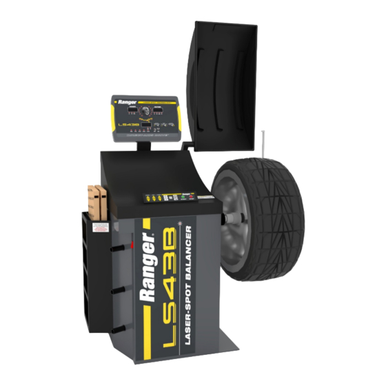
Installation and Operation Manual
Manual P/N 5900086 — Manual Revision A1 — December 2018
Model:
• LS43B
Designed and engineered in Southern California, USA. Made in China.
⚠
DANGER
Laser-Spot™ Wheel Balancer
Read the
product. Failure to follow the instructions and safety precautions in
this manual can result in serious injury or death. Make sure all other
operators also read this manual. Keep the manual near the product
for future reference. By proceeding with setup and operation, you
agree that you fully understand the contents of this manual.
entire
contents of this manual
1645 Lemonwood Dr.
Santa Paula, CA 93060 USA
Toll Free: (800) 253-2363
Tel: (805) 933-9970
rangerproducts.com
before
using this
Advertisement
Table of Contents

Subscribe to Our Youtube Channel
Related Manuals for Ranger Laser-Spot LS43B


Summary of Contents for Ranger Laser-Spot LS43B
- Page 1 1645 Lemonwood Dr. Santa Paula, CA 93060 USA Toll Free: (800) 253-2363 Tel: (805) 933-9970 rangerproducts.com Laser-Spot™ Wheel Balancer Installation and Operation Manual Manual P/N 5900086 — Manual Revision A1 — December 2018 Model: • LS43B Designed and engineered in Southern California, USA. Made in China. ⚠...
- Page 2 Warranty. The BendPak Ranger warranty is more than a commitment to you: it is also a commitment to the value of your new product. For full warranty details, contact your nearest BendPak Ranger dealer or visit bendpak.com/support/warranty.
-
Page 3: Table Of Contents
Maintenance Log Introduction This manual describes the Ranger LS43B Wheel Balancer, which is a computer-controlled Wheel Balancer that provides fast, accurate Wheel balancing for a wide variety of Wheels. The LS43B includes our exclusive Laser-Spot™ technology for precise weight placement. -
Page 4: Shipping Information
Make a visual inspection of the product before using it each time. Do not use the product if you find any missing or damaged parts. Instead, take the unit out of service, then contact an authorized repair facility, your distributor, or Ranger Products at (805) 933-9970. thorough •... - Page 5 BendPak Ranger assumes no liability for damages resulting from: • Use of the equipment for purposes other than those described in this manual. • Modifications to the equipment without prior, written permission from BendPak Ranger. • Damage to the equipment from external influences. •...
-
Page 6: Components
Components Balancer components include: • Display Panel. Shows information about what you are doing with the Balancer. • Hood. Covers the Wheel while it spins. • Inner Arm / Distance Ruler. Used to find the Distance between the Balancer and the inner edge of the Wheel being balanced. - Page 7 Balancer accessories include: • Quick-Release Hub Nut. Holds the Wheel on the Balancer, once the Wheel is mounted. • Hex Key Wrench Set. Used during installation. Hex key wrenches are sometimes called Allen® wrenches. • Anchor Bolts. Anchor the Balancer to the floor at the desired location. Anchoring the Balancer is optional, but strongly recommended.
-
Page 8: Faq
• Dynamic Balancing. Balancing a steel Wheel where each of the two planes are analyzed separately. If there is an imbalance, the two planes are brought back into balance separately. Dynamic Balancing is a more recent technology than Static Balancing and generally produces a better balance. -
Page 9: Specifications
Specifications Model LS43B Motor 220 VAC, 50/60 Hz, 1 Ph Working Temperature -5°C to 50°C / 27°F to 82°F Balancing Modes 1 dynamic / 1 static / 3 aluminum alloy / 1 hidden Maximum Tire Diameter 47" / 1,194 mm Maximum Tire Weight 145 lbs. - Page 10 Installation Checklist Following are the steps needed to install an LS43B Wheel Balancer. Perform them in the order shown. ☐ 1. Review the installation Safety Rules. ☐ 2. Plan for Electrical Work. ☐ 3. Make sure you have the necessary Tools. ☐...
-
Page 11: Installation
Certain parts of installing the Balancer are difficult for just one person. BendPak CAUTION Ranger strongly recommends having two or more persons work together to install the Balancer. If you have to use an extension cord, make sure its current rating is equal to or greater than that of the equipment being used. - Page 12 Finding a Location Keep in mind the following when deciding on a location: • Power source. The Balancer needs to be near an appropriate 220 VAC power source. • Floor. The Balancer is best used on a flat, concrete floor. If the floor is unstable or not flat, the Balancer will not work correctly;...
- Page 13 Important: weight of the Balancer. ⚠ Ranger recommends having at least two people move the Balancer; it is heavy. If it CAUTION is dropped or falls, it could cause injuries and/or the Balancer could be damaged. Components on the Back of the Balancer The Balancer has multiple components on the back that need to be installed.
- Page 14 The following drawing shows the components on the back of the Balancer. Not necessarily to scale. Not all components shown. The three Connectors are the same. Each cable fitting connects to one, and only one, of the three Connectors. Do not force a cable fitting into a Connector;...
- Page 15 Installing the Display Panel The Display Panel shows information about what is happening during the balancing of a Wheel. To install the Display Panel: 1. Locate the Display Panel and the Display Panel Mount Bar. – The Display Panel Base Plate (located on the bottom of the Display Panel Mount Bar, see drawing on previous page) connects to the back of the Balancer using four hex bolts, four split lock washers, and four standard washers;...
- Page 16 Installing the Mount Box The Mount Box holds both the Hood Mount Bar and the Outer Arm Mount Bar. It installs on the back of the Balancer on the left side. must Note: install the Mount Box before you can install the Hood or the Outer Arm. To install the Mount Box: 1.
- Page 17 Installing the Hood The Hood covers the Wheel while it spins during a Balancing. ⚠ CAUTION Keep away from the Hood and the Wheel while the Wheel is spinning. Touching the Wheel while it is spinning could result in injury. The following procedure assumes the Mount Box is already installed.
- Page 18 Installing the Outer Arm The Outer Arm is used to automatically establish the Diameter of the Wheel being balanced. Important: The following procedure assumes the Mount Box is already installed. If the Mount Box already installed, you must do it now. To install the Outer Arm: 1.
- Page 19 Installing the Shaft The Shaft holds the Wheels you are balancing. Consider having two people on hand to install the Shaft: one person to hold the Shaft Assembly in place while the second person screws in the Mounting Bolt. Also, consider having some rags nearby;...
- Page 20 Anchoring the Balancer The Balancer has three holes for Anchor Bolts, which hold the Balancer in place while you use it. required Important: You are to bolt your Balancer into place, as movement during a Wheel Balance can result in inaccurate readings. To anchor the Balancer: 1.
- Page 21 5. Hammer or mallet the Anchor Bolt the rest of the way down into the hole. Stop when the Washer is snug against the Base Plate. clockwise 6. Wrench each Nut to the recommended torque, 60 – 70 lbf-ft / 81 – 95 N-m. Important: use an impact wrench to torque the Anchor Bolts.
-
Page 22: Operation
Keep the work area clean and well lit. Dirty, cluttered, and dark work areas increase the chances of an accident happening. • Do not remove the Storage Trays unless instructed to do so by Ranger Support. There are no user serviceable parts underneath. •... - Page 23 Viewing Information on the Display Panel The Display Panel shows you information about the Wheel you are balancing. Note: There are no buttons to push on the Display Panel; it only displays information. The parts of the Display Panel include: •...
- Page 24 • Width Window. During the Measurements phase, this Window shows the Width of the Wheel (determined automatically from the measurements taken by the Inner and Outer Arms). • Indicators next to the Wheel. When Weight needs to be added to a Wheel, you turn the Wheel and watch the indicators on the appropriate side of the Wheel.
- Page 25 About Planes If you were to split a Wheel down the center (as shown below), it would be split into two “Planes”, an Inner plane and an Outer plane. both Balancing a Wheel on planes at the same time is the most effective method. Of the five Balancing Modes supported by the LS43B, four of them balance on two locations at the same time.
- Page 26 Because balancing a Wheel on both planes is so important for using the LS43B, the Display Panel shows a two-plane view of the Wheel being balanced. The Inner “Plane” is on the left (based on the main placement method for Wheels on the Balancer, where the visible Rim on the outside) and the Outer “Plane”...
- Page 27 About Measurements There are three measurements of a Wheel that are important to understand for correct balancing. The LS43B finds these measurements automatically when you use the Inner Arm and the Outer Arm. The three measurements are: • Distance. The distance from the side of the Balancer to the Inner Edge of the Wheel. Automatically measured by the Inner Arm.
- Page 28 Controlling the Balancer using the Control Panel The Control Panel is used to control aspects of the Balancer during both the Measurements phase and the Weights phase. • Distance, Width, Diameter + / — buttons. Used to change the Distance, Width, and Diameter settings during the Measurements phase of the balancing session (before you spin the Wheel).
- Page 29 Mounting a Wheel When you want to balance a Wheel, the first step is to mount it on the Shaft. Important: All Wheels should be mounted so that the inside (the side of the Wheel that goes closest to the Vehicle) goes on the Shaft first. There are three ways to mount a Wheel onto the Shaft: •...
- Page 30 • Dual-Cone Mounting. Generally used only for some aftermarket or OEM performance Wheels that have a center hole that is deep enough to allow the use of two cones on the Shaft. The Spring goes on first, then an appropriately sized Cone, the Wheel, a second appropriately sized Cone, and finally the Quick Nut.
- Page 31 Balancing Modes Balancing Modes are based on the locations where the weight gets put on if the Wheel is out of balance: • Dynamic (DYN). The most common Balancing Mode; used with steel rims. If the Wheel is out of balance, weights go on the Inner Edge and the Outer Edge.
- Page 32 OPT (Optimize) Function Not a Balancing Mode. The Optimize Function is an optional procedure to lessen the imbalance in a Wheel that is more than 30 grams / 1 ounce out of balance. For more information, refer to Using the Optimize Function.
- Page 33 Dynamic Balancing Dynamic Balancing balances a Wheel on both the Inner and Outer Edges. If the Wheel is out of balance, the Clip-On Weight can go on the Inner Edge, the Outer Edge, or both. To Balance a Wheel using Dynamic Mode: 1.
- Page 34 The value that appears in the Inner Window needs to be added to the Inner Edge of the Wheel. The value that appears in the Outer Window needs to be added to the Outer Edge of the Wheel. If either value is over 1 oz / 30 grams, Opt appears in the Width Window, meaning that the Optimize Function can be used.
- Page 35 Static Balancing Static Balancing is for older Wheels under 4 inches wide and motorcycle Wheels. Note: The Optimize Function is available for Static Mode. If the Wheel is out of balance, weight goes on the Center Plane when using Static Mode. To Balance a Wheel using Static Mode: 1.
- Page 36 Aluminum Alloy Balancing The following procedure describes the three Aluminum Alloy (ALU) Modes. Important: ALU Modes are for balancing Wheels made of aluminum alloy. The weights can be placed in various locations on these Wheels, so you need to know where you want to put the weights and then select the appropriate ALU Mode.
- Page 37 Using the Optimize Function The Optimize Function lets you help lessen the imbalance of a Wheel that is more than 1 ounce / 30 required grams out of balance. You are not to use the Optimize Function. The Optimize Function does not bring a Wheel to fully balanced; instead, it lessens the Important: imbalance of a Wheel that is significantly out of balance.
- Page 38 Hidden Weight Balancing Hidden Weight (HID) Mode hides Outer Plane Weight behind selected spokes on the Wheel so that they cannot be seen (as much as possible). Use ALU1 Mode for Hidden Weight Mode. With Hidden Weight Mode, Weight on the Inner Plane is used normally, while Adhesive Weights on the Outer Plane are split and mounted behind spokes.
-
Page 39: Maintenance
21. Press the ALU button. SPD appears. 22. Get the weight ready to be put on. 23. Turn the Wheel by hand until all of the Weight Position indicators on the OUTER side are fully illuminated. 24. Apply the weight displayed in the OUTER Window. 25. -
Page 40: Troubleshooting
Location Verification Test for more information. If you continue to have problems with your Wheel Balancer, visit www.bendpak.com/support/ call BendPak Ranger at (805) 933-9970. LS43B Laser-Spot™ Wheel Balancer P/N 5900086 — Rev. A1 — 12/212018... - Page 41 Calibrating the Outer Arm The Outer Arm Calibration makes sure the Outer Arm is returning correct values. Note: The Balancer comes from the factory correctly calibrated. You do not need to perform this calibration when you receive the Balancer. You only need to perform this calibration if you are seeing multiple incorrect Wheel balances.
- Page 42 Calibrating the Inner Arm The Inner Arm Calibration makes sure the Inner Arm is returning correct values. Note: The Balancer comes from the factory correctly calibrated. You do not need to perform this calibration when you receive the Balancer. You only need to perform this calibration if you are seeing multiple incorrect Wheel balances.
- Page 43 Weight Location Verification Test The Weight Location Verification Test ensures the Balancer is producing accurate readings. Before performing the Weight Location Verification Test, ma ke sure the Balancer is anchored down and/or rigid to the floor and that the shaft and centering cones are clean and undamaged. Dirt or damage can cause inaccurate readings.
-
Page 44: Wiring Diagram
Wiring Diagram LS43B Laser-Spot™ Wheel Balancer P/N 5900086 — Rev. A1 — 12/212018... -
Page 45: Labels
Labels LS43B Laser-Spot™ Wheel Balancer P/N 5900086 — Rev. A1 — 12/212018... - Page 46 LS43B Laser-Spot™ Wheel Balancer P/N 5900086 — Rev. A1 — 12/212018...
-
Page 47: Parts
Parts Part Number Description Weight Tray 5530304 Hex Socket Head Screws M8x20 Washer Φ8 Spring Washer Φ8 Flat Storage Cover Rocker Switch Hexgen socket head screws M6x30 Washer Φ6 Flat Hexgen Nut M6 Tool Shanking Hexagon Head Bolt Full Thread M8×20 Washer Φ8 Flat 5327993 Slide Storage Cover... - Page 48 Part Number Description Cross Recessed Pan Head Screw M4x12 Thread Shaft Plastic Cover Top Laser Light Assembly One Font Laser Light Source Laser Chassis Cross Recessed Pan Head Screw M4x12 5327505 Inner Hexagon End Set Screw M5x5 Lower Laser Light Assembly SHCS M4x20 Hexagon Socket Set Screw with Flat Point M4x4 Laser Stents...
- Page 49 Part Number Description Deformation of Beams SHCS M4x12 Tooth 64 Bearing Cover SHCS M6x20 Round Nut Snap Ring 30 mm Bearing 6006 Bearing 6005 5327179 Snap Ring 25 mm Axle Sleeve Assembly Part Number Description 5327330 Matcher SHCS M14x260 LS43B Laser-Spot™ Wheel Balancer P/N 5900086 —...
- Page 50 Part Number Description Hex Nut M10 Piezo Sensor Pad Sensor (Horizontal) 5327140 Piezo Horizontal Shaft 5327139 Piezo Vertical Shaft Sensor (Vertical) Sensor Wire Washer LS43B Laser-Spot™ Wheel Balancer P/N 5900086 — Rev. A1 — 12/212018...
- Page 51 Part Number Description 5327870 SHCS M4 x 8 Spring Pad Plain Washer Photovoltaic Panels Hex Nut Spring Pad Washer 5327686 Encoder Bracket Cross Recessed Pan Head Screw LS43B Laser-Spot™ Wheel Balancer P/N 5900086 — Rev. A1 — 12/212018...
- Page 52 Part Number Description Electromagnetic Brake Motor Plain Washer Spring Pad SHCS M6x16 5327144 Small Belt Pulley Motor Belt 5327145 Motor Pulley Key 5 x 5 x 30 Hexagon Head Bolt Full Thread Big Washer Motor Cabinet Rectifier Cross Recessed Pan Head Screw Transformer Balancer Cross Recessed Pan Head Screw Plain Washer φ6...
- Page 53 Part Number Description 5327591 Distance Arm Sticker 5328023 Distance Arm Spring Distance Arm Rod Distance Arm Rod Washer Snap Ring 20 5328022 Distance Arm Gear FHPS Wheel Distance Potentiometer Distance Arm Slide Block Wheel Diameter Potentiometer Hexagon Socket Set Screw with Flat Point M4x4 Cross Recessed Pan Head Screw M6x20 Washer 6 mm Flat Washer 6 mm Split Lock...
- Page 54 Caput Ulnare Cover Distance Arm Caput Bend Rod Cross Recessed Pan Head Screw 5328409 Distance Arm Assembly Distance Arm Slide Block Assembly Inner Distance Arm Assembly Part Number Description Nut M4 Washer 4 mm Split Lock Washer 6 mm Split Lock Cross Recessed Pan Head Screw M4x16 HHB M6x16 Nut M8...
- Page 55 Part Number Description Cross Recessed Pan Head Screw M3x25 Washer 3 mm Split Lock Nut M3 5328402 Computer Board LS43B Laser-Spot™ Wheel Balancer P/N 5900086 — Rev. A1 — 12/212018...
- Page 56 Part Number Description 5328407 Display Mounting Plate Cross Recessed Pan Head Screw M4x16 SHCS M10x20 Non-Metal Insert Self-Locking Nut 5328408 Display Support 5328408 SHCS M4x12 5328408 Back Shroud SHCS M4x20 SHCS M10x20 Non-Metal Insert Hexagonal Lock Nut Non-Metal Insert Hexagonal Lock Nut 5328419 U Channel Display Support Washer;...
- Page 57 Part Number Description SHCS M4x8 5328403 Display Baseplate 5328404 Display Board Display Board Cover Gommures Cross Slotted Half-Round Head Self-Tapping Screw 5328405 Display Board Mask 5328406 Display Cover 5328412 Display Board Top Harness Displayer Support Assembly LS43B Laser-Spot™ Wheel Balancer P/N 5900086 —...
- Page 58 Part Number Description 5328012 Hood Mounting Assembly Bracket Hood Switch Short Hood Switch Wires Hexagon Socket Set Screw with Flat Point M8x12 Hood Cam 5327168 Hood Spring 5327180 Adjustable Eye Bolt Hood Cam Stop Nut M8 SHCS M8x25 5327167 Hood Shaft Bushing Hood Rotating Shaft Snap Ring 38 mm SHCS M12x40...
- Page 59 Part Number Description Hood 5328246 Hood Mount Support SHCS M6x25 SHCS M6x25 Adjusting Plate Tire Guard Department Spring Pad Long Axis Front Axle Sleeve Spring Pad SHCS 5327505 Hexagon Socket Set Screw with Flat Point Column Buffer Cylinder LS43B Laser-Spot™ Wheel Balancer P/N 5900086 —...
- Page 60 Part Number Description 5327997 Touch Wand Arm BRKT SHCS M5x10 External Bracket Shaft Nut M10 Spring Washer SHCS M8x16 Touch Wand Pointer Subassembly Hexagon Socket Set Screw with Flat Point M6x6 Touch Wand Potentiometer Touch Wand Potentiometer Support Cross Recessed Pan Head Screw M4x10 5328054 Touch Wand Bracket Side 5328053...
- Page 61 Part Number Description 5327063 Spacer Ring 5327069 Cone 1 5327071 Cone 2 5327067 Cone 3 5327065 Cone 4 5327074 Quick Nut Cup Cover 5327061 Quick Nut Cup 5327172 Quick Nut Cover 5327073 Quick Nut 36 mm 5327720 Allen Wrench 12 mm 5328055 Allen Wrench 6 mm 5328056...
- Page 62 Part Number Description Connecting Wire Keyboard Wire Switch Wire Cover Wire Outer Measure Gauge Contact Wire Display Board Wire LS43B Laser-Spot™ Wheel Balancer P/N 5900086 — Rev. A1 — 12/212018...
-
Page 63: Maintenance Log
Maintenance Log LS43B Laser-Spot™ Wheel Balancer P/N 5900086 — Rev. A1 — 12/212018... - Page 64 1645 Lemonwood Drive Santa Paula, CA 93060 USA © 2018 BendPak Inc. All rights reserved. bendpak.com...
Need help?
Do you have a question about the Laser-Spot LS43B and is the answer not in the manual?
Questions and answers