Table of Contents
Advertisement
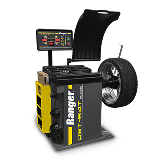
Installation and Operation Manual
Manual P/N 5900192 — Manual Revision F — March 2021
Models:
• DST-64T
• DST642D
Designed and engineered in Southern California, USA. Made in China.
⚠
DANGER
Wheel Balancers
entire
contents of this manual
Read the
product. Failure to follow the instructions and safety precautions
can result in serious injury or death. Make sure all operators read
this manual. Keep the manual near the product for future reference.
By proceeding with installation and operation, you agree
that you fully understand the contents of this manual and
assume full responsibility for product use.
1645 Lemonwood Dr.
Santa Paula, CA 93060 USA
Toll Free: (800) 253-2363
Tel: (805) 933-9970
rangerproducts.com
DST-64T shown.
before
using this
Advertisement
Table of Contents

Related Manuals for Ranger DST-64T


Summary of Contents for Ranger DST-64T
- Page 1 Tel: (805) 933-9970 rangerproducts.com Wheel Balancers Installation and Operation Manual Manual P/N 5900192 — Manual Revision F — March 2021 Models: • DST-64T • DST642D DST-64T shown. Designed and engineered in Southern California, USA. Made in China. ⚠ entire before...
- Page 2 Warranty. The BendPak Ranger warranty is more than a commitment to you: it is also a commitment to the value of your new product. For full warranty details, contact your nearest BendPak Ranger dealer or visit bendpak.com/support/warranty.
-
Page 3: Table Of Contents
Keep this manual on or near the equipment so that anyone who uses or services it can read it. Technical support for your Balancer is available from your distributor or directly from BendPak Ranger: using a web browser, visit the... -
Page 4: Shipping Information
Make a visual inspection of the product before using it each time. Do not use the product if you find any missing or damaged parts. Instead, take the unit out of service, then contact an authorized repair facility, your distributor, or Ranger Products at (805) 933-9970. thorough •... - Page 5 • Use of the equipment for purposes other than those described in this manual. • Modifications to the equipment without prior, written permission from BendPak Ranger. • Injury or death caused by modifying, disabling, overriding, or removing safety features. •...
-
Page 6: Components
Inner Arm / Distance Ruler. Used to find the distance between the Balancer and the inner edge of the Wheel being balanced. Not visible in the graphic below. • Outer Arm. Used to determine the outer edge of the Wheel being balanced. DST-64T only. • Brake Pedal. Used to hold the Wheel where it is. - Page 7 Mounting Spring. Secures the Wheel when using Rear- and Dual-Cone Mounting. • Inner and Outer Gauge Calibration Tool. Used for calibrating the unit, when necessary. The Outer Gauge Calibration Tool is only for the DST-64T. • Calibration Weight. A 100-gram Clip-On Weight used for the Dual-Plane Self-Calibration Procedure.
-
Page 8: Faq
FINE button on the Display Panel to see more specific values. Q: What do I do if I have a problem with the Balancer that I cannot solve? A: Contact BendPak Ranger; we are here to help. Using a web browser, visit the BendPak... -
Page 9: Specifications
39 in / 990 mm Depth, Hood Down 42 in / 1,067 mm Power Cord Length 63 in / 1,600 mm Working Temperature Range -5°C to +50°C / +23°F to +122°F DST-64T / DST642D Wheel Balancers P/N 5900192 — Rev. F — March 2021... -
Page 10: Installation Checklist
8. Install the Display Panel. ☐ 9. Install the Mount Box. ☐ 10. Install the Hood. ☐ 11. Install the Outer Arm (DST-64T only). ☐ 12. Install the Shaft. ☐ 13. Anchor the Unit. ☐ 14. Connect to a Power Source. -
Page 11: Installation
CAUTION Certain parts of installing the Balancer are difficult for just one person. BendPak Ranger strongly recommends having two or more persons work together to install the Balancer. If you have to use an extension cord, make sure its current rating is equal to or greater than that of the equipment being used. - Page 12 For safety purposes and to allow space to work with Wheels, a certain amount of space around the Balancer is needed. above You also need enough room the Balancer for the Hood to move up and down freely. DST-64T / DST642D Wheel Balancers P/N 5900192 — Rev. F — March 2021...
- Page 13 Balancer. ⚠ CAUTION Ranger recommends having at least two people move the Balancer; it is heavy. If it is dropped or falls, it could cause injuries and the Balancer could be damaged. DST-64T / DST642D Wheel Balancers...
- Page 14 About Display Plugs and Connectors for more information. • Mount Box. Connection point for the Hood Mount Bar and Outer Arm Mount Bar (DST-64T only). • Hood Mount Bar. Connects the Hood to the Mount Box. • Outer Arm Mount Bar. Connects the Outer Arm to the Mount Box (DST-64T only).
- Page 15 To attach the three Plugs to the three Connectors on the , match the number of holes in the Plug to the same number of pins in the Connector and attach them. DST-64T / DST642D Wheel Balancers P/N 5900192 — Rev. F — March 2021...
- Page 16 About Display Plugs and Connectors for additional information. Verify all seven Plugs and Connectors are correctly engaged. If they are easily removed then they are not installed correctly. DST-64T / DST642D Wheel Balancers P/N 5900192 — Rev. F — March 2021...
- Page 17 Shaft (the Hex Head Bolt Hole) and tighten the hex head bolt. Switching to the of the Hood Mount Arm , remove the two Hex Bolt and the Washers. DST-64T / DST642D Wheel Balancers P/N 5900192 — Rev. F — March 2021...
- Page 18 Slide the Rod through the Tube on the Outer Arm Mount Bar, then reattach the 4 mm Hex Bolt, Split Lock Washer, and large black plastic Washer you just removed. DST-64T / DST642D Wheel Balancers P/N 5900192 — Rev. F — March 2021...
- Page 19 Before fully tightening the Mounting Bolt, make sure the Alignment Marks (witness marks) are aligned (see drawing below). Not necessarily to scale. Not all components shown. Tighten the Mounting Bolt into place. DST-64T / DST642D Wheel Balancers P/N 5900192 — Rev. F — March 2021...
- Page 20 Make sure the Washer and Nut are in place, then insert the Anchor Bolt into the hole. The Expansion Sleeve of the Anchor Bolt may prevent the Anchor Bolt from passing through the hole in the Base Plate; this is normal. DST-64T / DST642D Wheel Balancers P/N 5900192 — Rev. F — March 2021...
- Page 21 Do not use an impact wrench to torque the Anchor Bolts. Wrenching the Nut forces the Wedge up, forcing out the Expansion Sleeve and pressing it tightly against the Concrete. DST-64T / DST642D Wheel Balancers P/N 5900192 — Rev. F — March 2021...
- Page 22 If the Wheel does not spin, it may have been configured to a manual start. The Auto-Hood function may be enabled/disabled by pressing Stop + C simultaneously. DST-64T / DST642D Wheel Balancers P/N 5900192 — Rev. F — March 2021...
- Page 23 Review the Installation Checklist to make sure all steps have been performed. • Check to see that all Anchor Bolts are in position and tightened. • Leave the Manual with the owner/operator. DST-64T / DST642D Wheel Balancers P/N 5900192 — Rev. F — March 2021...
-
Page 24: Operation
Keep the work area clean and well lit. Dirty, cluttered, and dark work areas increase the chances of an accident happening. • Do not remove the Tray unless instructed to do so by Ranger Support. There are no user serviceable parts underneath. must •... - Page 25 Width Window. During the Measurements phase, this Window shows the Width of the Wheel. Determined automatically from the measurements taken by the Inner and Outer Arms (DST-64T Only). Data is manually entered using the Distance, Width and Diameter buttons on the DST-642D.
- Page 26 Only needed if you want to enter these values manually on the DST64T and the DST-642D; otherwise, use the Inner Arm and Outer Arm to have the Balancer determine these values automatically (DST-64T only). DST-64T / DST642D Wheel Balancers P/N 5900192 — Rev. F — March 2021...
- Page 27 Distance + will display units from g to oz. and oz. to g. Also used with the C button to toggle the Auto-hood function on-off. Press Stop+C to toggle off, press Stop+C again to toggle back on. DST-64T / DST642D Wheel Balancers P/N 5900192 — Rev. F — March 2021...
- Page 28 The OUTER Window shows how much weight to place on either the Outer Edge or the Outer Plane weight locations. The Placement Indicators, six vertical LEDs per Plane, all light up when the best weight location is reached. DST-64T / DST642D Wheel Balancers P/N 5900192 — Rev. F — March 2021...
- Page 29 • Diameter. The distance from Outer Edge to Outer Edge. Automatically measured by the Outer Arm on the DST-64T. Read from the sidewall of the Tire or measured using the Caliper and entered manually on the DST642D. Inputting Measurement Data Manually...
- Page 30 Rear-Cone Mounting. Use this method if the Wheel you are balancing cannot be mounted with Front-Cone Mounting. The Spring goes on first, then an appropriately sized Cone, the Wheel, the Quick Nut Cap, and finally the Quick Nut. DST-64T / DST642D Wheel Balancers P/N 5900192 — Rev. F — March 2021...
- Page 31 Important: Do not hammer or hit the Quick Nut to tighten it. You will damage the Quick Nut, which is not covered under the Warranty. DST-64T / DST642D Wheel Balancers P/N 5900192 — Rev. F — March 2021...
- Page 32 Center Plane can be split up and hidden behind spokes in the Wheel. Refer to Hidden Weight Balancing for specific instructions for using this Balancing Mode. DST-64T / DST642D Wheel Balancers P/N 5900192 — Rev. F — March 2021...
- Page 33 Weight Applicator, it is usually going to be at Top Dead Center. In most cases, it will be somewhere between 10 o’clock and 12 o’clock. DST-64T / DST642D Wheel Balancers P/N 5900192 — Rev. F — March 2021...
- Page 34 On power up, baL xx appears in the Inner and Outer Windows. The xx is a numeric value that indicates the software version being used. After a few seconds, default values appear in the Distance, Width, and Diameter Windows. DST-64T / DST642D Wheel Balancers P/N 5900192 — Rev. F — March 2021...
- Page 35 Note: The Inner Window always shows distance in centimeters (cm). The Distance Ruler on the Inner Arm is graduated in centimeters and cannot be modified. If using the DST-64T, place the tip of the Outer Arm on the Outer Edge of the Wheel and hold it wait for the Balancer to beep there;...
- Page 36 12 o’clock on the Outer Edge. Lower the Hood to spin the Wheel again. The Wheel is balanced when both the Inner and Outer Windows show 00. DST-64T / DST642D Wheel Balancers P/N 5900192 — Rev. F — March 2021...
- Page 37 Outer Plane Wheel Positions light. Hold the wheel in place at this position with the Brake. Add the correct amount of weight at 12 o’clock Top Dead Center. DST-64T / DST642D Wheel Balancers P/N 5900192 — Rev. F — March 2021...
- Page 38 Turn the Wheel slowly to find the best location to put the weight. When the Wheel is in the right location, all the Inner and Outer Plane indicator LEDs light. Hold the Wheel in position using the Brake. DST-64T / DST642D Wheel Balancers P/N 5900192 — Rev. F — March 2021...
- Page 39 The Width Window on the Display counts down as you approach the correct location. When you are at the exact right location, the Width Window shows -0. DST-64T / DST642D Wheel Balancers P/N 5900192 — Rev. F — March 2021...
- Page 40 After the beep, return the Inner Arm to its rest position. Make sure that ALU is selected (this should be done automatically). If ALU mode is automatically selected, restart the procedure. DST-64T / DST642D Wheel Balancers P/N 5900192 — Rev. F — March 2021...
- Page 41 Return the Inner Arm to its rest position. q. Lower the Hood to spin the Wheel again. The Wheel is balanced when both the Inner and Outer Windows show 00. DST-64T / DST642D Wheel Balancers P/N 5900192 — Rev. F — March 2021...
- Page 42 Inner and Outer Display Windows. Rotate the Wheel by hand until all the Inner Plane Position Indicators are lit. Apply the Brake to hold the Wheel in place. DST-64T / DST642D Wheel Balancers P/N 5900192 — Rev. F — March 2021...
- Page 43 Top Dead Center. Hold in position with the brake and push ALU (this defines the angular distance of the first split weight measured from the ideal weight location. DST-64T / DST642D Wheel Balancers P/N 5900192 — Rev. F — March 2021...
- Page 44 The Balancer will automatically stop and switch back to ALU mode. After the Wheel stops, the weight corrections for the Inner and Outer Planes should be 0. DST-64T / DST642D Wheel Balancers P/N 5900192 — Rev. F — March 2021...
- Page 45 Tire so the two Marks you just put on are aligned, then put the Tire back on the Wheel. Put the Wheel back on the Balancer and restart the Balancing process that was interrupted by using the Optimize Function. DST-64T / DST642D Wheel Balancers P/N 5900192 — Rev. F — March 2021...
-
Page 46: Maintenance
Do not operate your Wheel Balancer if you find issues; instead, take the unit out of service, then contact your dealer, visit rangerproducts.com/support/, or call (805) 933-9970. DST-64T / DST642D Wheel Balancers P/N 5900192 — Rev. F — March 2021... -
Page 47: Troubleshooting
The Outer Arm is not producing Calibrate the Outer Arm. Refer to Calibrating the Outer correct values on a consistent basis. for more information. DST-64T only. The Inner Arm is not producing Calibrate the Inner Arm. Refer to Calibrating the Inner correct values on a consistent basis. - Page 48 Calibrating the Outer Arm (DST-64T only) The Outer Arm Calibration makes sure the Outer Arm on the DST-64T is returning correct values. Note: The Balancer comes from the factory correctly calibrated. You do not need to perform this calibration when you receive the Balancer. You only need to perform this calibration if you are seeing multiple incorrect Wheel balances.
- Page 49 If you mounted a 15" diameter Wheel, you don’t have to change anything. Put the Head of the Distance Ruler on the Inner Edge of the Wheel, then press ALU. Calibration is complete. DST-64T / DST642D Wheel Balancers P/N 5900192 — Rev. F — March 2021...
- Page 50 Wheel will automatically spin when the Hood is lowered. The Wheel spins briefly, then stops. Add 100 appears in the Display (Add 3.5 if ounces is selected). DST-64T / DST642D Wheel Balancers P/N 5900192 — Rev. F — March 2021...
- Page 51 The 100-gram Wheel weight should be at 6 o’clock Bottom Dead Center. Remove the 100-gram Wheel weight from the Outer edge of the Wheel. Install the 100-gram Wheel weight on the Inner edge of the Wheel. DST-64T / DST642D Wheel Balancers P/N 5900192 — Rev. F — March 2021...
- Page 52 Turn the Wheel by hand until the Inner Placement Indicators are all lit. The 100-gram Wheel weight should be at 6 o’clock Bottom Dead Center. The Weight Location Verification Test is complete. DST-64T / DST642D Wheel Balancers P/N 5900192 — Rev. F — March 2021...
-
Page 53: Wiring Diagram
Use a dedicated breaker for the Balancer. • Most electrical codes require “hard-wiring” when the machine is bolted to the floor. Consult a licensed Electrician regarding the applicable codes for your location. DST-64T / DST642D Wheel Balancers P/N 5900192 — Rev. F — March 2021... -
Page 54: Labels
Labels DST-64T labels shown. Label E not present on DST642D; A through D are the same for both models. DST-64T / DST642D Wheel Balancers P/N 5900192 — Rev. F — March 2021... - Page 55 DST-64T / DST642D Wheel Balancers P/N 5900192 — Rev. F — March 2021...
-
Page 56: Parts
SHCS, M8 by 16 5327132 Cone Hanger 5327993 Side Storage Rack 5327994 On/Off Switch Matcher 5327995 Motor Power Board 5327996 Weight Tray 5327997 Touch Wand Arm Bracket 5327998 Bearing 2010 DST-64T / DST642D Wheel Balancers P/N 5900192 — Rev. F — March 2021... - Page 57 Transformer HHB, M6 by 25 Washer, 6 mm Split Lock Washer Label 2 Pinboard Inner Gauge Wire Display Column Cover 5328304 SHCS, M5 by 10 Big Washer DST-64T / DST642D Wheel Balancers P/N 5900192 — Rev. F — March 2021...
- Page 58 Nut, M10 Pizo Sensor Pad 5327141 Vertical Pizo Sensor 5327139 Pizo Vertical Shaft 5327140 Pizo Horizontal Shaft 5328009 Weight Indicator Light Chuck Guard SSS ST 4.8 by 16 DST-64T / DST642D Wheel Balancers P/N 5900192 — Rev. F — March 2021...
- Page 59 Hood Mounting Assembly Upper Cover SHCS, M8 by 20 Washer, 8 mm Flat 5328014 Hood Mounting Assembly Threaded Shaft/Spindle with Position Board Washer, 8 mm Split Lock Sensor Flat Mat DST-64T / DST642D Wheel Balancers P/N 5900192 — Rev. F — March 2021...
- Page 60 Brake Pedal Return Spring 5327169 Hood Switch Cross Recessed Pan Head Screw, M3 by 20 Brake Bracket Kit Nut, M10 Washer, 6 mm Flat Presser Rubber Bushing DST-64T / DST642D Wheel Balancers P/N 5900192 — Rev. F — March 2021...
- Page 61 Left Brake Stop 5328042 Brake Bracket 5328135 Break Friction Wheel Motor Assy (110/220V 0.55KW) Brake Assembly Nut, M6 HHB, M8 by 25 Washer Washer, 8 mm Split Lock DST-64T / DST642D Wheel Balancers P/N 5900192 — Rev. F — March 2021...
- Page 62 Snap Ring, 20 by 1 External Gauge Spring Hook External Gauge Connector 5328046 Touch Wand Rod Hood Assembly Set Screw, M6 by 6 5328047 Touch Wand Pointer Coupling DST-64T / DST642D Wheel Balancers P/N 5900192 — Rev. F — March 2021...
- Page 63 5328053 Touch Wand Bracket Cover 5328054 Touch Wand Bracket Side Cross Recessed Pan Head Screw, M4 by 10 Washer, 10 mm Split Lock SHCS, M6 by 30 DST-64T / DST642D Wheel Balancers P/N 5900192 — Rev. F — March 2021...
- Page 64 Anchor Bolt, 3/8 in by 3 ½ in 5346425 Weight Hammer Pliers 5346879 Calibration Weight (100 grams) 5402252 Mounting Spring, 36 mm 5402187 Wheel Width Caliper 5328062 Accessory Box, 36 mm 5328058 Extension Leve DST-64T / DST642D Wheel Balancers P/N 5900192 — Rev. F — March 2021...
- Page 65 Distance Arm Nut 5327998 Bearing 2010 Cross Recessed Pan Head Screw, M6 by 40 Internal Pad 3 Distance Arm Basement 5328018 Distance Arm Sticker SHCS, M6 by 16 DST-64T / DST642D Wheel Balancers P/N 5900192 — Rev. F — March 2021...
- Page 66 Washer, 12 mm Flat 5328028 Distance Arm Head Weight 5328029 Distance Arm Head Pivot 5328030 FHPS, M5 by 30 SMS 5328043 Distance Arm Head Assy 5328018 Distance Arm Sticker DST-64T / DST642D Wheel Balancers P/N 5900192 — Rev. F — March 2021...
- Page 67 SHCS, M6 by 25 Adjusting Plate Close Over Tire Guard Department Spring Pad, 6 mm Long Axis Front Axle Sleeve Spring Pad SHCS, M12 by 35 Long Axis DST-64T / DST642D Wheel Balancers P/N 5900192 — Rev. F — March 2021...
- Page 68 Side Storage Rack Washer, 8 mm Flat SHCS, M8 by 16 5327132 Cone Hanger Chassis Body 5327994 On/Off Switch Matcher 5327995 Motor, 220V 0.55 KW 5328071 Power Board Assembly DST-64T / DST642D Wheel Balancers P/N 5900192 — Rev. F — March 2021...
- Page 69 Display Column Cover 5328071 Power Board, 220 V Type B Reed Nut, M6 Cross Recess Brazier Head Screw, M6 by 20 Socket Hexagon Socket Head Screw with Flange Face DST-64T / DST642D Wheel Balancers P/N 5900192 — Rev. F — March 2021...
- Page 70 5327140 Pizo Horizontal Shaft 5328009 Weight Indicator Light Chuck Guard SSS, ST 4.8 by 16 5328010 Thread Shaft Plastic Cover 5327141 Pizo Wires SHCS, M4 by 12 DST-64T / DST642D Wheel Balancers P/N 5900192 — Rev. F — March 2021...
- Page 71 SHCS, M8 by 20 Washer, 8 mm Flat 5328014 Hood Mounting Assembly 5327143 Spindle with Position Board Washer, 8 mm Split Lock Sensor Flat Mat SHCS, M10 by 16 DST-64T / DST642D Wheel Balancers P/N 5900192 — Rev. F — March 2021...
- Page 72 Cross Recessed Pan Head Screw, M3 by 20 Brake Bracket Kit Nut, M10 Washer, 6 mm Flat Presser Rubber Bushing 5328137 Motor Bracket 5327995 Motor, 110/220V 0.55 KW DST-64T / DST642D Wheel Balancers P/N 5900192 — Rev. F — March 2021...
- Page 73 Left Brake Stop 5328042 Brake Bracket 5328135 Brake Friction Wheel Motor Assembly, 110/220V 0.55 KW Brake Assembly Nut, M6 HHB, M8 by 25 Washer Washer, 8 mm Split Lock DST-64T / DST642D Wheel Balancers P/N 5900192 — Rev. F — March 2021...
- Page 74 Anchor Bolt, 3/8 in by 3 ½ in 5346425 Weight Pliers 5346879 Calibration Weight, 100 grams 5402252 Mounting Spring, 36 mm 5402187 Wheel Width Caliper 5328062 Accessory Box, 36 mm 5328058 Extension Lever DST-64T / DST642D Wheel Balancers P/N 5900192 — Rev. F — March 2021...
- Page 75 Washer, 6 mm Flat Washer, 6 mm Split Lock Cross Recessed Pan Head Screw, M6 by 20 Hexagon Socket Set Screw with Flat Point, M4 by 4 DST-64T / DST642D Wheel Balancers P/N 5900192 — Rev. F — March 2021...
- Page 76 Washer, 12 mm Flat 5328028 Distance Arm Head Weight 5328029 Distance Arm Head Pivot Bushing 5328030 FHPS, M5 by 30 SMS 5328043 Distance Arm Head Assembly 5328018 Distance Arm Sticker DST-64T / DST642D Wheel Balancers P/N 5900192 — Rev. F — March 2021...
- Page 77 SHCS, M6 by 25 SHCS, M6 by 25 Adjusting Plate Tire Guard Department Spring Pad, 6 mm Long Axis Front Axle Sleeve Spring Pad SHCS, M12 by 35 DST-64T / DST642D Wheel Balancers P/N 5900192 — Rev. F — March 2021...
-
Page 78: Maintenance Log
Maintenance Log DST-64T / DST642D Wheel Balancers P/N 5900192 — Rev. F — March 2021... - Page 79 Maintenance Log DST-64T / DST642D Wheel Balancers P/N 5900192 — Rev. F — March 2021...
- Page 80 1645 Lemonwood Drive Santa Paula, CA 93060 USA © 2021 BendPak Inc. All rights reserved. bendpak.com...
Need help?
Do you have a question about the DST-64T and is the answer not in the manual?
Questions and answers