Advertisement
INSTALLATION AND OPERATION MANUAL
MODEL
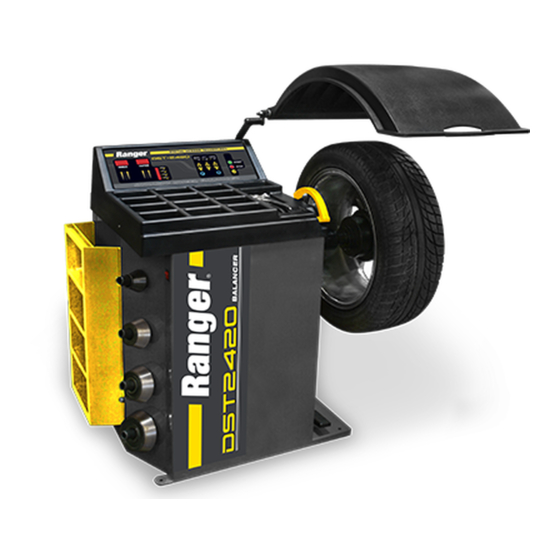
DST-2420
WHEEL BALANCER
FOR BALANCING
AUTOMOBILE,
MOTORCYCLE
& LIGHT TRUCK
TIRES / WHEELS
Keep this operation manual near the
machine at all times. Make sure that
ALL USERS read this manual.
SHIPPING DAMAGE CLAIMS
When this equipment is shipped, title passes to the
purchaser upon receipt from the carrier. Consequently,
claims for the material damaged in shipment must be
made by the purchaser against the transportation
company at the time shipment is received.
PLEASE READ THE ENTIRE CONTENTS OF THIS MANUAL PRIOR
TO INSTALLATION AND OPERATION. BY PROCEEDING YOU
AGREE THAT YOU FULLY UNDERSTAND AND COMPREHEND
THE FULL CONTENTS OF THIS MANUAL. FORWARD THIS
MANUAL TO ALL OPERATORS. FAILURE TO OPERATE THIS
EQUIPMENT AS DIRECTED MAY CAUSE INJURY OR DEATH
BE SAFE
Your new Ranger balancer was designed and built
with safety in mind. However, your overall safety
can be increased by proper training and thoughtful
operation on the part of the operator.
DO NOT operate or repair this equipment without
reading this manual and the important safety
instructions shown inside.
REV A 06-21-10
p/n# 5900233
1645 Lemonwood Dr.
Santa Paula, CA. 93060, USA
Toll Free 1-800-253-2363
Tel: 1-805-933-9970
Fax: 1-805-933-9160
www.rangerproducts.com
.
Advertisement
Table of Contents

Related Manuals for Ranger DST-2420


Summary of Contents for Ranger DST-2420
- Page 1 SHIPPING DAMAGE CLAIMS BE SAFE When this equipment is shipped, title passes to the Your new Ranger balancer was designed and built purchaser upon receipt from the carrier. Consequently, with safety in mind. However, your overall safety claims for the material damaged in shipment must be...
- Page 2 Installation and Setup BendPak Inc. / Ranger Products Mounting the Hood ..... . 6 1645 Lemonwood Dr., Installing the Threaded Shaft.
-
Page 3: Definition Of Hazard Levels
This warranty is exclusive and in lieu of all other warranties expressed or implied. In no event shall BendPak Inc. / Ranger Products be liable for special, consequential or incidental damages for the breach or delay in performance of the warranty. BendPak Inc. - Page 4 IMPORTANT SAFETY INSTRUCTIONS! READ BEFORE OPERATING UNIT! Protective goggles, safety glasses, or a face shield Avoid unintentional starting. Be sure the balancer is must be worn by the operator. Care should be taken to turned off before servicing. see that all eye and face safety precautions are followed by the operator.
-
Page 5: Electrical Requirements
BEFORE YOU BEGIN position the switch located at the back of the machine to the desired voltage setting before installing the required plug if necessary. Receiving The shipment should be thoroughly inspected as soon as it is received. The signed bill of lading is acknowledge- ment, by the carrier, of receipt in good condition of the ship- ment. -
Page 7: Initial Start-Up
4. Slide the Hood Arm over the Hood Axle, align the holes in INSTALLING THE the Axle with the Allen bolts then secure in place using the THREADED MAIN SHAFT two allen set screws. 1. Locate the Face Plate / Threaded Main Shaft and mounting bolt in the accessory box and install as shown. -
Page 8: Control Panel And Display
BALANCER OVERVIEW The wheel diameter will be referred as the DIAMETER MEASUREMENT. This is the diameter of the wheel at the weight location. You can determine the diameter of the wheel This machine is a two-plane, microprocessor-based / tire on the tire sidewall to determine the wheel diameter. Or computer balancer. -
Page 9: Gram / Ounce Selection
SELECTING WEIGHT POSITIONS GRAM / OUNCE SELECTION FOR DIFFERENT WHEEL TYPES This machine is capable of registering GRAM or OUNCE readings. To select either GRAM or OUNCE settings, follow Prior to balancing, a specific FUNCTION must the procedures below. be chosen for each particular wheel. The function settings automatically compensate 1. -
Page 10: Front Cone Mounting
MOUNTING WHEELS Front Cone Mounting A wheel should be centered by the outer side of the Select the most appropriate mounting method for the hub only when the inner surface will not provide an accurate wheel you are balancing. Using the proper method ensures surface to center on. -
Page 11: Dual Cone Mounting
The cones must not contact each other and a correct cone combination is critical to correctly mount a tire using this method. (Extra centering cones are available though Ranger Products) 1. Slide the Spring onto the Arbor. Select the cone combination that best fits both sides of the center hole in the wheel. - Page 12 BALANCING INSTRUCTIONS Inputting Wheel Data Prior to balancing any wheel, specific data relating to that particular wheel must be entered into the computer. If the 1. First determine which mounting method you will use for data displayed on the screen does not match that of the the wheel.
- Page 13 4. Pull the index arm out from the side of the machine until “dia” - Wheel Diameter the tip touches the inner edge of the wheel. This is the diameter of the wheel at the rim flanges. This measurement can be read on the tire sidewall. Or mea- sured.
- Page 14 2. After the hood is lowered, or the START button is 6. After the INNER weight is properly installed, turn the depressed, the wheel will spin for approximately six wheel by hand until the weight position indicator lights on seconds then stop automatically. the side marked OUTER are fully illuminated.
-
Page 15: Spin Mode / Static
Spin Mode / STATIC STOP BUTTON This function is used if weights can only be mounted on The STOP button IS an emergency a single plane of the wheel. stop button. It will immediately shut down the shaft and wheel rotation. For emergency 1. - Page 16 (Using the cone to secure against the fl ange) for the most security and stability. (Rear Cone Mounting uses the Pressure Cup assembly.) (Extra centering cones are available though Ranger Products.) If any the above conditions were found, the condition must be remedied and the balancer must be re-calibrated.
- Page 17 10. Place one 100 gram weight (included with balancer) on the outer edge of the rim. If the location is not as Bottom Dead Center (6 o’clock), please contact the Ranger Products Customer Service 11. Close the hood and press the START button. The wheel Department.
- Page 18 Computer Display Board and or read the Parameter Settings Sticker. NOTE: Complete instructions for replacing the Computer/Power Board are included with the Power Board Service Kit available from Ranger Products. Remove all weights and tools from the top of the weight tray.
- Page 19 Carefully support the Weight Tray while noting the Parameter Setting Values located on the Parameter Settings Sticker located on the inside wall of the front panel of the machine. 7. Note the Parameter Setting Values before reassembly, they will be needed after cover is closed. Reassemble the Weight Tray and Distance Arm and proceed to resetting the Parameter Settings.
-
Page 20: Resetting Parameter Settings
RESETTING PARAMETER SETTINGS When checking/modifying the “dIS” setting is complete, press Distance button below move on to the next parameter setting. Press and hold the R button and the NOTE: Once you move on to the next parameter setting, you must restart this procedure if you would like Start button at the same time until the to edit the dIS value again. - Page 21 14. Press the button below to modify the values to match the values shown on the Parameter Settings Sticker. 15. When checking/modifying the SFA setting is complete, press Distance button below to move on to the next parameter setting. 16. Once you are done checking/modifying the SFA setting, press Distance + to move save the changes.
- Page 26 DRAWING DESCRIPTION DRAWING DESCRIPTION Transformer Membrane Switch Power Board Plastic Tray Cover Resistor Wheel Guard Power Mounting Plate Wheel Guard Support Computer / Display Board Brake Pad Voltage Selector Switch Brake pad Spacer Shelves Brake Bracket Hanger Spring Power Switch Brake Fixed Plate Chassis Body Brake Square Plate...
-
Page 27: Tire & Wheel Data
TIRE AND WHEEL DATA ________________________________________________________________________________ ________________________________________________________________________________ ________________________________________________________________________________ ________________________________________________________________________________ ________________________________________________________________________________ ________________________________________________________________________________ ________________________________________________________________________________ ________________________________________________________________________________ ________________________________________________________________________________ ________________________________________________________________________________ ________________________________________________________________________________ ________________________________________________________________________________ ________________________________________________________________________________ ________________________________________________________________________________ ________________________________________________________________________________ ________________________________________________________________________________ ________________________________________________________________________________ ________________________________________________________________________________ ________________________________________________________________________________ ________________________________________________________________________________ ________________________________________________________________________________ ________________________________________________________________________________ ________________________________________________________________________________ ________________________________________________________________________________... - Page 28 For Parts Or Service Contact: BendPak Inc. / Ranger Products 1645 Lemonwood Dr. Santa Paula, CA 93060 Toll Free 1-800-253-2363 Tel: 1-805-933-9970 Fax: 1-805-933-9160 www.bendpak.com www.rangerproducts.com p/n# 5900233...
Need help?
Do you have a question about the DST-2420 and is the answer not in the manual?
Questions and answers