Table of Contents
Advertisement
Quick Links
Advertisement
Table of Contents

Related Manuals for Kontron CP6924-1


Summary of Contents for Kontron CP6924-1
- Page 1 User Guide CP6924-1 Document Revision 1.0 Date: December, 2015 www.kontron.com...
-
Page 2: Revision History
Disclaimer Copyright © 2015 Kontron AG. All rights reserved. All data is for information purposes only and not guaranteed for legal purposes. Infor- mation has been carefully checked and is believed to be accurate; however, no responsibility is assumed for inaccuracies. Kontron and the Kontron logo and all other trademarks or registered trademarks are the property of their respective owners and are recognized. -
Page 3: Table Of Contents
CP6924-1 User Guide Contents Revision History ......................... 2 Imprint ..........................2 Disclaimer ........................2 Proprietary Note ........................ 8 Trademarks ........................8 Environmental Protection Statement ..................8 Advisory Conventions ......................8 Safety Instructions ......................9 General Instructions on Usage .................... 11 Two Year Warranty ...................... - Page 4 4.2.4 Routing Package MIBs ................... 52 4.2.5 QoS Package MIBs ..................52 4.2.6 Multicast package MIBs .................. 52 4.2.7 Security MIBs ....................53 4.2.8 Kontron Private MIBs ..................53 Bootloader ...................... 54 4.3.1 Power On Self Test ..................55 4.3.2 Bootloader Shell Options ................56 4.3.3 Bootloader Pushbutton Reset ................
- Page 5 CP6924-1 User Guide IPMI Firmware ....................59 4.4.1 Supported IPMI Commands ................59 4.4.2 Board Sensors ....................65 4.4.3 Board FRU Information .................. 75 Software Administration ..................76 4.5.1 Updating System Software ................77 4.5.2 Updating IPMI Firmware ................. 78 Thermal Considerations ....................
- Page 6 CP6924-1 User Guide List of Tables Table 1-1: CP6924 Software Specification................17 Table 3-1: Ethernet Port Mapping ..................26 Table 3-2: Peripheral Manager AD Input and Voltage Assignment........... 28 Table 3-3: SFP Uplink Port Pinout ..................31 Table 3-4: Front RJ45 Ethernet Connector ................. 32 Table 3-5: Front RS232....................
- Page 7 List of Figures Figure 3-1: CP6924-1 Functional Block Diagram ..............25 Figure 3-2: Front Panel of the CP6924-1-RA-OC ..............29 Figure 3-3: Front Panel of the CP6924-1-SA-OC-V ..............29 Figure 3-4: CP6924-1 Front Panel LEDS ................30 Figure 5-1: Position of Temperature Sensors, Top Side View ............ 79...
-
Page 8: Proprietary Note
This document contains information proprietary to Kontron. It may not be copied or transmitted by any means, disclosed to others, or stored in any retrieval system or media without the prior written consent of Kontron AG or one of its authorized agents. -
Page 9: Safety Instructions
It was also designed for a long fault-free life. However, the life expectancy of your product can be drastically reduced by improper treatment during unpacking and installation. Therefore, in the interest of your own safety and of the correct operation of your new Kontron product, you are requested to conform with the following guidelines. - Page 10 CP6924-1 User Guide Laser Lights Laser light from fiber-optic transmission cables and components can damage your eyes. The laser components plugged into the switch are Class 1 laser components. Class 1 laser is considered incapable of pro- ducing damaging radiation levels during normal operation or mainte- nance.
-
Page 11: General Instructions On Usage
TWO YEAR LIMITED HARDWARE WARRANTY ing. However, no other warranties that may be granted or implied by anyone on behalf of Kontron are valid unless the con- sumer has the express written consent of Kontron. -
Page 12: Introduction
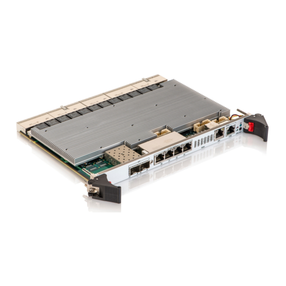
CP6924-1 User Guide Introduction Product Overview The CP6924-1 is a Standard Fabric 6U CompactPCI Gigabit Ethernet Switch with 24 channels compliant to PICMG 2.16. The board is available in three variants: • CP6924-1-RA-OC 20x rear GbE + 4x front GbE ports (switchable to rear IO) + 2x 10G SFP+. -
Page 13: General Compliances
CP6924-1 User Guide • 10/100/1000Base-T Management Port via Copper PHY BCM54610 connected to FP RJ45 • 2x UART connects to CPLD • Configuration EEPROM • I2C Interface and SPI Interface to CPLD • NVRAM write protection • PPC405EX supports JTAG Boundary Scan 1.1.1.3... -
Page 14: Technical Specification
Compliant to PICMG® 2.0 6U/4HP (233.35 mm x 160 mm). • Weight: • CP6924-1-RA-OC and CP6924-1-SA-OC-V: 720g • CP6024-1-RC: 1170g The CP6924-1-RA-OC and CP6924-1-SA-OC-V use a front panel. The CP6924-1-RC does not need a front panel. 1.2.3 Temperature Compliant to IEC 60068-2-1 and IEC 60068-2-2. • CP6924-1-RA-OC •... -
Page 15: Shock
1000 Hz to 2000 Hz PSD decreasing at 6 dB/octave Note... If the CP6924-1 board is used in heavy shock and vibration environment, the hole system must withstand these requirements. This means the chassis, backplane and guiderails should be designed for harsh environment. Guide rails with wedge locks are recommend. -
Page 16: Reliability
CP6924-1 User Guide • EN61000-6-3 (Europe) • EN61000-6-2 (Europe) • VCCI (Voluntary Japan Electromagnetic Compatibility requirement) • EN 300 386, Electro-Magnetic Compatibility (EMC) Requirements for Public Telecommunication Network Equipment; Electromagnetic Compatibility (EMC) Requirements 1.2.10 Reliability Targeted MTBF is around 140.000h @ 30° C, calculations based on Bellcore Issue 6. -
Page 17: Software Support
CP6924-1 User Guide Software Support The following table contains information related to software supported by the CP6924. Table 1-1: CP6924 Software Specification CP6924 SPECIFICATIONS • General Reliable field upgrades for all software components • Dual boot images with roll-back capability •... - Page 18 CP6924-1 User Guide Table 1-1: CP6924 Software Specification (Continued) CP6924 SPECIFICATIONS • Applications SNTP client for retrieving accurate time and date information • DHCP server • Onboard event management • Test and trace facilities • POST (power on self tests) diagnostics •...
-
Page 19: Installation
Safety Requirements The following safety precautions must be observed when installing or operating the CP6924. Kontron assumes no responsi- bility for any damage resulting from failure to comply with these requirements. WARNING Due care should be exercised when handling the board due to the fact that the heat sink can get very hot. -
Page 20: Cp6924 Initial Installation Procedures
CP6924-1 User Guide CP6924 Initial Installation Procedures The following procedures are applicable only for the initial installation of the CP6924 in a system. Procedures for standard removal and hot swap operations are found in their respective chapters. To perform an initial installation of the CP6924 in a system proceed as follows: 1. -
Page 21: Standard Removal Procedures
CP6924-1 User Guide Standard Removal Procedures To remove the board proceed as follows: 1. Ensure that the safety requirements indicated in chapter Safety Requirements are observed. WARNING Care must be taken when applying the procedures below to ensure that nei- ther the CP6924 nor other system boards are physically damaged by the application of these procedures. -
Page 22: Quick Start
The procedure for assigning an IP address to the serviceport is described in the following. User input is printed in bold let- ters. 1. Connect to serial port on the front plate (using the Kontron DB9 adapter cable) or RIO module (using a RJ45 straight cable). -
Page 23: In-Band Cli Access
The procedure for assigning an IP address to the network port is described in the following. User input is printed in bold let- ters. 1. Connect to serial port on the front plate (using the Kontron DB9 adapter cable) or RIO module (using a RJ45 straight cable). - Page 24 CP6924-1 User Guide 5. Save configuration by using the ‘write mem’ command and confirm ’y’ (Ethernet Fabric) #write mem This operation may take a few minutes. Management interfaces will not be available during this time. Are you sure you want to save? (y/n) y Config file 'current/startup-config' created successfully.
-
Page 25: Functional Description
CP6924-1 User Guide Functional Description This chapter describes the board specific items of the CP6924-1. The base board is a standard Fabric 6U CompactPCI Gigabit Ethernet Switch with 24 channels. Figure 3-1: CP6924-1 Functional Block Diagram www.kontron.com... -
Page 26: Ethernet Infrastructure
CP6924-1 User Guide The board is composed of the following building blocks: • Ethernet Infrastructure • Unit Computer and Memory • IPMI • Power Supply Ethernet Infrastructure The fabric switch infrastructure is composed of • Broadcom StrataXGS®IV Chip BCM56334 with 24x 1GbE Ports (SGMII) and 4x 10GbE (XAUI) •... -
Page 27: Unit Computer And Memory
*) These ports are connected to a multiplexer which allows the user to switch the four lanes individually to the backplane ports (FL) or to the uplink ports (FP). **) Only availabe for the CP6924-1-RA-OC version. Unit Computer and Memory The Unit Computer controls the Ethernet infrastructure and hosts the management application. -
Page 28: Voltage Sensors
CP6924-1 User Guide The PM uses the following outputs to control the CP6924: • Power and Reset control of the payload • IMPB A and IMPB B support • LED HEALTHY (not on CP6924-RC) • Unit Computer reset The Peripheral Manager provides additional feature and is equipped with following peripherals: •... -
Page 29: Board Interfaces
Front Panel of the CP6924-1-SA-OC-V 3.4.1.2 CP6924-1-RC Front Panel The CP6924-1-RC does not have a front panel. 3.4.2 Front Panel Switches The Handle Switch is actuated with the lower ejector handle of the board. It is used to signal the inserting or impending extraction of the board. -
Page 30: Front Panel Leds
CP6924-1 User Guide 3.4.3 Front Panel LEDS Figure 3-4: CP6924-1 Front Panel LEDS Hot Swap LED (Blue LED) • payload activated • ready for hot swap • Blinking not specified yet LED1 Alarm (red) • all sensor values are within their specified range •... -
Page 31: Front Panel Ports
CP6924-1 User Guide Ethernet Link Port Status LEDs (24 fabric interface LEDs for status indication) • link down • link up but no activity • Blinking link up and activity CPU 10/100/1000Base-T Management port LEDs Link/Activity: green LED • link down •... -
Page 32: Front Panel Management Port Rj45
CP6924-1 User Guide Table 3-3: SFP Uplink Port Pinout Signal 3.3V RX 3.3V TX 1) MODDEF2 is used as SFP+ SDA signal MODDEF1 is used as SFP+ SCL signal MODDEF0 is used as SFP+ PRESENT signal PIN9, GND is used as RATE2_SELECT 3.4.5... -
Page 33: Table 3-5: Front Rs232
CP6924-1 User Guide 3.4.5.1 Front Panel RS232 The Front RS232 RJ45 has the following Pin Assignment Table 3-5: Front RS232 Direction Signal Connection to the front RS232 port is established with a straight through Ethernet cable and a RJ45 (female) to SubD (female) adapter if required. -
Page 34: Compactpci Connectors
CP6924-1 User Guide 3.4.6 CompactPCI Connectors The complete CompactPCI connector configuration comprises five connectors named J1 to J5. Their functions are as fol- lows: • J1, J2: management, IPMB and power, PCI is not supported • J3, J4 and J5 have rear I/O interface functionality, providing GbE to the backplane or RIO module and an RS232 in- terface to a RIO module The board supports signaling voltages V(I/O) of either 3.3 V or 5 V. -
Page 35: Table 3-8: Connector J2 Pinout
CP6924-1 User Guide 3.4.6.2 J2 Connector • Geographical Address • IPMB 1 • ALERT# Table 3-8: Connector J2 Pinout Row A Row B Row C Row D Row E Row F CPCI_GA[4] CPCI_GA[3] CPCI_GA[2] CPCI_GA[1] CPCI_GA[0] IPMB1_SDA IPMB1_SCL IPMB_ALERT# www.kontron.com... -
Page 36: Table 3-9: Connector J3 Pinout
CP6924-1 User Guide 3.4.6.3 J3 Connector • Link Port 1 to Link Port 8 (10/100/1000Base-T) • Link Port f • Shelf Geographical Address Table 3-9: Connector J3 Pinout Row A Row B Row C Row D Row E Row F... -
Page 37: Table 3-10: Connector J4 Pinout
CP6924-1 User Guide 3.4.6.4 J4 Connector • RS232 Interface (RX/TX) Table 3-10: Connector J4 Pinout Row A Row B Row C Row D Row E Row F FL20_DA+ FL20_DA- FL20_DC+ FL20_DC- FL20_DB+ FL20_DB- FL20_DD+ FL20_DD- FL21_DA+ FL21_DA- FL21_DC+ FL21_DC- FL21_DB+... -
Page 38: Write Protection Feature
CP6924-1 User Guide 3.4.6.5 J5 Connector • PICMG 2.16 Link Port 9 to Link Port 19 (10/100/1000Base-T) Table 3-11: Connector J5 Pinout Row A Row B Row C Row D Row E Row F FL_DA19+ FL_DA19- FL_DC19+ FL_DC19- FL_DB19+ FL_DB19-... -
Page 39: Software Description
This manual describes bootloader, Linux rootfs/kernel and IPMI firmware, last chapter introduces the update procedures. For additional information of system configuration using CLI commands refer to documentation “CP6924-1 CLI Reference Manual”. -
Page 40: Switching
CP6924-1 User Guide • RFC 3412 - Message Processing and Dispatching (December 2002) • RFC 3413 - SNMP Applications (December 2002) • RFC 3414 - User-based Security Model (December 2002) • RFC 3415 - View-based Access Control Model (December 2002) •... - Page 41 CP6924-1 User Guide • IEEE 802.3ab — 1000BASE-T • IEEE 802.3ac — VLAN tagging • IEEE 802.3ad — Link aggregation • IEEE 802.3ae — 10 GbE • IEEE 802.3x — Flow control • ANSI/TIA-1057 — LLDP-MED • GARP — Generic Attribute Registration Protocol: clause 12, 802.1D-2004 •...
-
Page 42: Routing
CP6924-1 User Guide • RFC 951 — BootP • RFC 1321 — Message digest algorithm • RFC 1534 — Interop. between BootP and DHCP • RFC 2030 — Simple Network Time Protocol (SNTP) V4 for IPv4, IPv6, and OSI •... -
Page 43: Qos
CP6924-1 User Guide 4.1.4 DiffServ • RFC 2474 — Definition of the differentiated services field (DS Field) in the IPv4 and IPv6 headers • RFC 2475 — An architecture for differentiated services • RFC 2597 — Assured forwarding PHB group •... -
Page 44: Multicast
CP6924-1 User Guide 4.1.5 Multicast • RFC 1112 — Host extensions for IP multicasting • RFC 2236 — IGMP v2 • RFC 2710 — MLDv1 • RFC 2365 — Administratively scoped boundaries • RFC 3376 — IGMPv3 • RFC 3810 — MLDv2 •... -
Page 45: Fastpath Switching
CP6924-1 User Guide • RFC 3415 — View-based Access Control Model • RFC 3416 — Version 2 of SNMP Protocol Operations • RFC 3417 — Transport Mappings • RFC 3418 — Management Information Base (MIB) for the Simple Network Management Protocol (SNMP) •... - Page 46 CP6924-1 User Guide • IEEE 802.3ab — 1000Base-T • IEEE 802.3ac — VLAN tagging • IEEE 802.3ad — Link aggregation • IEEE 802.3ae — 10GbE • IEEE 802.3x — Flow control • ANSI/TIA-1057 — LLDP-MED • GARP — Generic Attribute Registration Protocol: clause 12, 802.1D-2004 •...
-
Page 47: Fastpath Routing
CP6924-1 User Guide • RFC 791 — IP • RFC 792 — ICMP • RFC 793 — TCP • RFC 826 — Ethernet ARP • RFC 894 — Transmission of IP Datagrams over Ethernet Networks • RFC 896 — Congestion Control in IP/TCP Networks •... -
Page 48: Fastpath Ipv6 Routing
CP6924-1 User Guide • RFC 3046 — DHCP/BOOTP relay • RFC 3101 — The OSPF “Not So Stubby Area” (NSSA) option • RFC 3107 — Carrying label information in BGP-4 • RFC 3137 — OSPF Stub Router Advertisement • RFC 3623 — Graceful OSPF Restart •... -
Page 49: Fastpath Quality Of Service
CP6924-1 User Guide 4.1.10 FASTPATH Quality of Service DiffServ • RFC 2474 — Definition of the differentiated services field (DS Field) in the IPv4 and IPv6 headers • RFC 2475 — An architecture for differentiated services • RFC 2597 — Assured forwarding PHB group •... -
Page 50: Fastpath Multicast
CP6924-1 User Guide 4.1.11 FASTPATH Multicast Core Features • RFC 1112 — Host extensions for IP multicasting • RFC 2236 — IGMP v2 • RFC 2365 — Administratively scoped boundaries • RFC 2710 — MLDv1 • RFC 3376 — IGMPv3 •... -
Page 51: Switching Package Mibs
CP6924-1 User Guide • RFC 3417 - SNMPV2-TM • RFC 3415 - View-based Access Control Model for SNMP MIB • RFC 3411 - SNMP-FRAMEWORK-MIB • RFC 3412 - SNMP-MPD-MIB • RFC 3413 - SNMP-NOTIFICATION-MIB • RFC 3413 - SNMP-PROXY-MIB (initial revision published as RFC 2273) •... -
Page 52: Routing Package Mibs
CP6924-1 User Guide • RFC 3291 — Textual Conventions for Internet Network Addresses • RFC 3635 — Etherlike MIB • RFC 3636 — IEEE 802.3 Medium Attachment Units (MAUs) MIB • RFC 4022 — Management Information Base for the Transmission Control Protocol (TCP) •... -
Page 53: Security Mibs
Ethernet features • Geographical Address • extended management features Kontron specific MIBs start with a “kex_”. Here‘s a list of MIBs provided (in this example for release GA 2.0) including its content: • kex_config • Set BSP startup services •... -
Page 54: Bootloader
SNMP can also be used for updating System Software, IPMI FW and PLD. Bootloader On the CP6924-1 Ethernet Switch, the bootloader 'u-boot' (universal bootloader) is used. The bootloader initializes the main components of the system like Unit Computer, DDR2 RAM, serial lines etc. for operation and performs a power on self test (POST). -
Page 55: Power On Self Test
CP6924-1 User Guide 4.3.1 Power On Self Test 4.3.1.1 Test Routines Upon power on or system reset, the bootloader performs the following power on self tests (POST): Table 4-1: POST tests Test Description Serial Onboard Unit Computer serial controller loopback test... -
Page 56: Bootloader Shell Options
CP6924-1 User Guide 4.3.2 Bootloader Shell Options The boot process can be interrupted by entering the bootstopkey phrase “stop”. This will open a bootloader shell session. Entering “?” provides a list of possible built-in commands, “printenv” provides a list of current environment settings. The bootloader shell can be used to customize boot options and system startup by changing some of its environment variables. - Page 57 CP6924-1 User Guide Table 4-3: Bootloader Environment Variables (Continued) Name Type Description contains the default base MAC address of the board which is read from VPD area. If ethaddr environment variable is changed and stored ethaddr Auto using 'saveenv', this value will override VPD setting af ter board restart.
-
Page 58: Bootloader Pushbutton Reset
4.3.3 Bootloader Pushbutton Reset When the pushbutton is pressed, the CP6924-1 glue logic performs a SysReset to the CPU. After reset has been issued, the board will restart with boot source 'Pushbutton' displayed on the serial console. If the pushbutton has been pressed for more than 3s, bootloader will detect this and drop into the boot firmware shell immediately. -
Page 59: Ipmi Firmware
CP6924-1 User Guide IPMI Firmware The Switch Management Controller communicates with the onboard Module Management Controller (MMC) using the Key- board Controller Style (KCS) interface. The bootloader is able to communicate with the MMC, e.g. for POST error logging purposes and fault resilient purposes. - Page 60 CP6924-1 User Guide Table 4-4: Standard Commands (Continued) IPMI 2.0 Spec. Support on Command NetFn section CP6924-1 Chassis Commands Chassis Control 28.3 Chassis O / Yes Event Commands Set Event Receiver 29.1 M / Yes Get Event Receiver 29.2 M / Yes Platform Event (a.k.a.
-
Page 61: Table 4-5: Hpm.1 Commands
HPM.1 Get Upgrade Status HPM.1 Activate Firmware HPM.1 Query Self-Test Results HPM.1 Query Rollback Status HPM.1 Initiate Manual Rollback HPM.1 4.4.1.2 Kontron OEM Commands and Extensions Table 4-6: Kontron OEM Commands Command NetFn Code OemApSetControlState OemApGetControlState OemApGetFirmwareSysUpTime OemApFormatStorage OemApSetSdrLocatorString OemApSetSerialNumber... - Page 62 Byte Data Field Request Data Completion Code Device ID 10h = Kontron IPMC based on NXP Microcontroller Device Revision [7] - 1b = device provides Device SDRs [6-0] – 0000000b = Reserved Firmware Revision [7] – 0b = normal operation [6:0] –...
- Page 63 CP6924-1 User Guide Example: # ipmitool bmc info Device ID : 16 Device Revision Firmware Revision : 0.90 IPMI Version : 1.5 Manufacturer ID : 15000 Manufacturer Name : Kontron Product ID : 1704 (0x06a8) Product Name : Unknown (0x6A8)
- Page 64 CP6924-1 User Guide OemApSetNvData / OemApGetNvData Command These commands provide raw access to the internally held parameter database that is stored inside the I2C EEPROM attached to the IPMI controller. NetFn oemApSetNvData OEM = 3Eh Byte Data Field Pass Code 0: ~’K’...
-
Page 65: Board Sensors
CP6924-1 User Guide OemApLoadNvDefaults Command This command is used to re-initialize the parameter database to its default values. NetFn oemApLoadNvDefaults OEM = 3Eh Byte Data Field Pass Code 0: ~’K’ Pass Code 1: ~’o’ Request data Pass Code 2: ~’n’... -
Page 66: Table 4-7: Sensor List
CP6924-1 User Guide For OEM (Kontron) specific sensor types and reading types in the following table please refer to the next chapter. Table 4-7: Sensor List Sensor Sensor ID Sensor Type Code Description Record ID CP6924 FRU Device Locator Record... - Page 67 CP6924-1 User Guide Example # ipmitool sdr list S02:T_PCB | 32 degrees C | ok S02:T_PHY1 | 53 degrees C | ok S02:T_PHY2 | 64 degrees C | ok S02:T_PHY3 | 44 degrees C | ok S02:V_0V9_VTT | 0.90 Volts...
-
Page 68: Table 4-8: Ipmb Link (Type C3H) Reading
CP6924-1 User Guide 4.4.2.2 OEM Sensors OEM IPMB Link (Type C3h) Table 4-8: IPMB Link (Type C3h) Reading Offset Request data Sensor Number Completion Code Sensor Reading [7:4] – Reserved, ignore on read [3] – IPMB-L Override State 0b = override state, bus isolated 1b = local control state, MMC determines state of the bus [2:0] –... -
Page 69: Table 4-9: Ipmb Link (Type C3H) Event Message
CP6924-1 User Guide Table 4-9: IPMB Link (Type C3h) Event Message Offset Event Message Rev Sensor Type F2h – Module Hot Swap Sensor Number [7] – Event Direction 1b = Deassertion 0b = Assertion [6-0] – Event Type 6Fh = Generic Availability Event Data 1 [7:4] –... -
Page 70: Table 4-10: Mmc Reboot (Type 24H) Reading
CP6924-1 User Guide MMC Reboot (Type 24h) Table 4-10: MMC Reboot (Type 24h) Reading Offset Request data Sensor Number Completion Code Sensor Reading 00h – ignore on read Standard IPMI Byte. (See “Get Sensor Reading in the IPMI Specification) Response data [7:2] –... -
Page 71: Table 4-12: Mmc Fwup (Type C7H) Reading
CP6924-1 User Guide MMC FwUp (Type C7h) Table 4-12: MMC FwUp (Type C7h) Reading Offset Request data Sensor Number Completion Code Sensor Reading 00h = first boot after upgrade 01h = first boot after rollback Response data All other values are reserved. -
Page 72: Table 4-14: Post Fail (Type 0Fh) Reading
CP6924-1 User Guide POST Fail (Type 0Fh) Table 4-14: POST Fail (Type 0Fh) Reading Offset Request data Sensor Number Completion Code Sensor Reading 00h – ignore on read Response data Standard IPMI Byte. (See “Get Sensor Reading in the IPMI Specification) [7:1] –... -
Page 73: Table 4-16: Boot Fail (Sensor Type 1Eh) Reading
CP6924-1 User Guide Boot Fail *(Sensor Type 1Eh) Table 4-16: Boot Fail (Sensor Type 1Eh) Reading Offset Request data Sensor Number Completion Code Sensor Reading 00h – ignore on read Standard IPMI Byte. (See “Get Sensor Reading in the IPMI Specification) [7:4] –... -
Page 74: Table 4-18: Temperature Sensor Thresholds [°C]
CP6924-1 User Guide * Standard sensor type from IPMI2.0 defined for x86 systems. 4.4.2.3 Sensor Thresholds Following tables show sensor thresholds for temperature, voltage and current sensors. Table 4-18: Temperature Sensor Thresholds [°C] SENSOR Number/ ID Lower criti- Lower non... -
Page 75: Board Fru Information
Supported are the following FRU data areas and data fields (shown values are examples, which may differ, depending on the used board typ): FRU Board Info Area • Manufacturing date / time • Board manufacturer: “KONTRON ” • Board Product Name: “ S1704” • Board Serial Number : “0123456789” *) • Board Part Number: “1055-1103”... -
Page 76: Software Administration
CP6924-1 User Guide Software Administration A running CP6924-1 system requires – after the bootloader has passed control to the kernel – the kernel itself, the root file system (initrd), the FASTPATH switching application and the IPMI firmware. The system supports an on-board integrated 1x128 MB NOR flash that is also used as the power-up boot source. It contains the bootloader as well as the operating system and the application data. -
Page 77: Updating System Software
The CLI commands described below are executed in the privileged mode of the CLI hierarchy, which is entered by executing the ‘enable’ command. Please refer to the “CP6924-1 CLI Reference Manual“ for more information regarding the CLI com- mands and the way to use them. -
Page 78: Updating Ipmi Firmware
CP6924-1 User Guide (Ethernet Fabric) #reload In case of problems with booting the system, last working backup image will automatically be copied to active image. This procedure restores normal system behavior. Configuration settings made with active image are lost and should be saved by copying active image to backup image before. -
Page 79: Thermal Considerations
CP6924-1 User Guide Thermal Considerations The CP6924 has four temperature sensors which ensure operation within the specified temperature limits. Sensor data is accessible via the Peripheral Manager. Although temperature sensing information is made available to the PM, the CP6924 itself does not provide any active means of temperature regulation. -
Page 80: Table 5-1: Thermal Requirements
For the CP6924-1-RC-C, the specified temperature refers to the mean temperature of both spacers (metal strips along the PCB edge, bottom side) - these are the reference points according Vita 47.1. -
Page 81: Power Considerations
CP6924-1 User Guide Power Considerations The power considerations presented in this chapter must be taken into account by system integrators when specifying the CP6924 system environment. Baseboard The CP6924 has been designed for optimal power input and distribution. Still it is necessary to observe certain criteria essential for application stability and reliability. - Page 82 CP6924-1 User Guide CORPORATE OFFICES Europe, Middle East & Africa North America Asia Pacific Lise-Meitner-Straße 3-5 14118 Stowe Drive 17 Building,Block #1, ABP. 86156 Augsburg Poway, CA 92064-7147 188 Southern West 4th Ring Road Germany Beijing 100070, P.R.China Tel.: + 49 (0) 821 / 4086 01 Tel.: + 1 888 294 4558...
Need help?
Do you have a question about the CP6924-1 and is the answer not in the manual?
Questions and answers