
Related Manuals for Kontron VX3910


Summary of Contents for Kontron VX3910
- Page 1 VX3910 High-performance OpenVPX Switch User's Guide CA.DT.A81-2e March 2011 If it's embedded, it's Kontron.
- Page 2 Initial Issue 09-2010 Copyright © 2011 Kontron AG. All rights reserved. All data is for information purposes only and not guaranteed for legal purposes. Information has been carefully checked and is believed to be accurate; however, no responsibility is assumed for inaccuracies. Kontron and the Kontron logo and all other trademarks or registered trademarks are the property of their respective owners and are recognized.
- Page 3 This document contains information proprietary to Kontron. It may not be copied or transmitted by any means, disclosed to others, or stored in any retrieval system or media without the prior written consent of Kontron or one of its authorized agents.
- Page 4 Therefore, in the interest of your own safety and of the correct operation of your new Kontron product, you are requested to conform with the following guidelines.
- Page 5 General Instructions on Usage In order to maintain Kontron’s product warranty, this product must not be altered or modified in any way. Changes or modifications to the device, which are not explicitly approved by Kontron and described in this manual or received from Kontron’s Technical Support as a special handling instruction, will void your warranty.
-
Page 6: Table Of Contents
........... VX3910 Initial Installation Procedures . - Page 7 VX3910 User's Guide Table Of Contents 3.1.2 10/100/1000BASE-T Gigabit Ethernet Interfaces ........
- Page 8 ............Figure 8: Location of battery on VX3910-RC boards .
- Page 9 ............Table 3: VX3910-SA MTBF Data .
-
Page 10: Chapter 1 - Introduction
Introduction Product Overview The VX3910 is a Standard Fabric 3U OpenVPX Gigabit Ethernet Switch with 24 channels providing Layer 2 and Layer 3 switching/routing functions in a 3U VPX compliant form factor. The product features 24 x 1000BASE-BX ports to the VPX backplane plus 3 x 1 GbE front panel Interfaces. -
Page 11: General Compliances
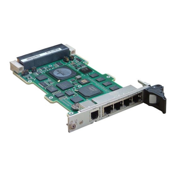
> Standard Air (SA) and Rugged Conduction-Cooled (RC) builds 1.1.2 General Compliances The board is compatible to the following standards: > IEEE 802.3, 2000 > IEEE 802.3ae, 2002 > VITA 46.0 VPX Base Specification > ANSI/VITA 65-2010 OpenVPX System Specification Figure 1: VX3910-SA Overview Page 2 CA.DT.A81-2e... -
Page 12: Figure 2: Vx3910-Rc Overview
VX3910 User's Guide Introduction Figure 2: VX3910-RC Overview CA.DT.A81-2e Page 3... -
Page 13: Ordering Information
VX3910 User's Guide Introduction Ordering Information Manufacturing Options > Rear Panel Interfaces: Option 1: 24x 1000BASE-BX Option 2: 22x 1000BASE-BX + 1x 1000BASE-T > Front Panel Size 0.8 inch inch > Ruggedization Levels: Standard Air-Cooled (SA) Rugged Conduction-Cooled (RC) Order Code Available... -
Page 14: Technical Specification
VX3910 User's Guide Introduction Technical Specification 1.3.1 Power Supply voltages are: > 5 Volts Power consumption of the VX3910: > Idle (no links): > Typical: > Maximum (full traffic/load): 1.3.2 Mechanics > 3U VPX board occupying 1 slot (4 HP) >... -
Page 15: Safety
VX3910 User's Guide Introduction 1.3.5 Safety The board is designed to meet the following requirements: > UL 60950, 3rd edition (US and Canada) > EN 60950 (Europe) > LVD 73/23/EEC (Europe) > Denan Law (Japan Safety) The board is designed to meet the following flammability requirement (as specified in telcordia GR-63-CORE): >... -
Page 16: Reliability / Mtbf
40°C 40°C 25°C 40°C 55°C Order Code: VX3910-SA-20200 273 676 202 682 45 126 52 955 45 446 12 945 Table 3: VX3910-SA MTBF Data VX3910-RC-2N200 GB (Hours) NS (Hours) (Hours) (Hours) 25°C 40°C 40°C 25°C 40°C 55°C Order Code: VX3910-2N200... -
Page 17: Software Support
VX3910 User's Guide Introduction Software Support The following table contains information related to software supported by the VX3910. VX3910 SPECIFICATIONS - Reliable field upgrades for all software components - Dual boot images with roll-back capability General - Management via SNMP and Command Line Interface - System access via TELNET, SSH and serial line - Static link aggregation (IEEE 802.3ad) -
Page 18: Table 5: Vx3910 Software Specification
- U-Boot Version 1.3.4 - POST - Multi-image support Bootloader - Reliable field upgradable - H/W protected - KCS interface to PM - Serial console support Operating System - Wind River PNE 2.0 Table 5: VX3910 Software Specification CA.DT.A81-2e Page 9... -
Page 19: Chapter 2 - Installation
In addition, the board should not be placed on any surface or in any form of storage container until such time as the board and heat sink have cooled down to room temperature. Be careful when inserting or removing the VX3910. The SFP cages have sharp edges which might lead to injuries. -
Page 20: Vx3910 Identification
Installation VX3910 Identification The VX3910 boards are identified by labels fitted to the top side. "Order Code, Variant, Serial Number and E.C. Level" labels (Versions Text and 2D available). "PLD, Ethernet Address, EEP and Firmware" labels (Versions Text and 2D available). -
Page 21: Vx3910 Configuration
VX3910 User's Guide Installation VX3910 Configuration MicroSwitch SW2 MicroSwitch SW1 1 2 3 4 1 2 3 4 Figure 4: Microswitches Location Page 12 CA.DT.A81-2e... -
Page 22: Microswitch Sw1 Description
VX3910 User's Guide Installation 2.3.1 Microswitch SW1 Description Function Description ETH15 location 1 - ETH15_LAN_SWITCH on: rear panel off: front panel (default) 2 - Reserved PCIe Common Clock Selection 3 - CC_SEL on: Internal reference clock or P1 reference clock... -
Page 23: Figure 5: Vpx Clock Diagram
VX3910 User's Guide Installation P0_SEL CC_SEL Internal Clock 1:2 MUX ICS9DBL411 FSUSB30 1:4 BUFFER CLK_EN1 1:2 MUX ICS9DBL411 ICS_557_06 FSUSB30 CLK_EN0 P1_SEL Figure 5: VPX Clock Diagram Page 14 CA.DT.A81-2e... -
Page 24: Vx3910 Initial Installation Procedures
Installation VX3910 Initial Installation Procedures The following procedures are applicable only for the initial installation of the VX3910 in a system. Procedures for standard removal operations are found in section 2.5 Standard Removal Procedures To perform an initial installation of the VX3910 in a system proceed as follows: 1. -
Page 25: Standard Removal Procedures
1. Ensure that the safety requirements indicated in section 2.1 Safety Requirements are observed. Care must be taken when applying the procedures below to ensure that neither the VX3910 nor other system boards are physically damaged by the application of these procedures. -
Page 26: Quick-Start
2.7.1.2 Fast Ethernet Serviceport The Gigabit Ethernet serviceport on the VX3910 front plate has no IP address set by default, it is necessary to assign an IP address statically or enable dhcp on the serviceport. Because the required configuration steps are done in the CLI, an initial access using the serial port is required. -
Page 27: In-Band Cli-Access
The procedure for assigning an IP address to the network port is described in the following. User input is printed in bold letters. 1. Connect to serial port on the front plate (using the Kontron DB9 adapter cable) or RIO module (using a RJ45 straight cable). - Page 28 To access the CLI via Fast Ethernet networkport, open a telnet connection to the configured IP address, port 23. It might make sense to separate the management network from the data path by setting appropriate VLANs For additional information on the system configuration, refer to the VX3910 CLI Reference Manual. CA.DT.A81-2e Page 19...
-
Page 29: Chapter 3 - Functional Description
VX3910 User's Guide Functional Description Chapter 3 - Functional Description The board is composed of the following building blocks: > Ethernet Infrastructure > Unit Computer and Memory > Glue Logic > JTAG Page 20 CA.DT.A81-2e... -
Page 30: Figure 6: Functional Block Diagram Vx3910
VX3910 User's Guide Functional Description I2C 0 Figure 6: Functional Block Diagram VX3910 CA.DT.A81-2e Page 21... -
Page 31: Ethernet Infrastructure
VX3910 User's Guide Functional Description Ethernet Infrastructure 3.1.1 Gigabit Ethernet Multilayer Switch Device The Gigabit Ethernet Multilayer Switch device is a Broadcom BCM56224B. The BCM56224B is a highly integrated and cost-effective multilayer Ethernet switch from the Broadcom StrataXGS® product line. It is a single-chip solution with a high-performance 32-bit MIPS CPU and 28 GbE ports. -
Page 32: Table 8: Bcm56224B Port Mapping
(1) CH0 is the internal link between the CPU and the switch (2) Depending on the SW1_1 microswitch configuration (refer to section 2.2 “VX3910 Configuration” page 11) (3) UCH3 ... UCH0 are the four ports for 1 Gigabit Ethernet (GbE) uplink/stacking See Hardware Release Note CA.DT.A85 about the issue on these ports. -
Page 33: 3.1.1.1 Pci
3.1.1.3 JTAG The JTAG Interface is connected to the JTAG chain on the VX3910. JTDI is connected to the TDO from the preceding device (PCIe to PCI Bridge) in the JTAG chain and JTDO is connected to the following device (BCM5482S) in the JTAG chain. -
Page 34: Pcie To Pci Bridge
> PCIe 1 lane 2.5 Gbps Gen 1 > PCI 32-bit/66 MHz > 144-pin BGA The PEX 8112 is able to connect up to four PCI devices. On the VX3910 only the BCM56224B switch is connected as device 0 on the PCI bus. BCM56224B... -
Page 35: Unit Computer And Memory
VX3910 User's Guide Functional Description Unit Computer and Memory The Unit Computer controls the Ethernet infrastructure and hosts the management application. It is a PowerPC PPC405EX with the following features: > 600 MHz core frequency > PCIe management connection to Ethernet Switch >... -
Page 36: Figure 8: Location Of Battery On Vx3910-Rc Boards
> 100 KHz I2C interface, address read A2h, address write A3h > Battery back-up for up to 10 years Not available on VX3910-RC boards. Figure 8: Location of battery on VX3910-RC boards Temperature Sensors The National Semiconductor LM73 connects to PPC405EX I2C #0 >... -
Page 37: Glue Logic
VX3910 User's Guide Functional Description Glue Logic The VX3910 glue logic is an Altera CPLD EPM2210F256 with the following functions: > Power control 4 Monitor Power Good Signals > Reset control 4 Reset distribution 4 Reset inputs > PPC405EX interface... -
Page 38: Write Protection Feature
VX3910 User's Guide Functional Description Write Protection Feature The backplane signal NVMRO defines the protection: > If NVMRO is set to High, all non volatile memory is read only, write protected. > If NVMRO is set to Low, all non volatile memory is not write protected. -
Page 39: Board Interfaces
VX3910 User's Guide Functional Description Board Interfaces 3.5.1 Front Panel Status LEDs and Reset Button Figure 9: Front Panel of the VX3910-SA Status LEDs > Green LED, Healthy, ON = Switch operational Red LED, Fault, ON = Switch fault >... -
Page 40: Front Panel Ports
3.5.2 Front Panel Ports Copper Uplinks SERIAL MGMT Figure 10: Front Panel Ports of the VX3910-SA MGMT Figure 11: Front Panel Ports of the VX3910-RC SERIAL > 1x RJ11 for Management (RJ11 connector), see section 3.5.2.1 “Serial Interface” page 32. -
Page 41: 3.5.2.1 Serial Interface
VX3910 User's Guide Functional Description 3.5.2.1 Serial Interface SIGNAL Pin 1 Pin 6 Shell Figure 12: Serial Connector Table 11: Serial Connector Pin Assignment MNEMONIC DESCRIPTION EIA-232 Clear-To-Send EIA-232 Ready-To-Send EIA-232Receive Data EIA-232 Transmit Data Ground Chassis Ground Shell Table 12: Serial Connector Signal Description Page 32 CA.DT.A81-2e... -
Page 42: 3.5.2.2 Gigabit Ethernet Management Interface
VX3910 User's Guide Functional Description 3.5.2.2 Gigabit Ethernet Management Interface The Ethernet transmission can operate effectively using a CAT5 cable with a maximum length of 100 m. The Gigabit Ethernet MAC of the PPC405EX is used as a management interface. A Gigabit Ethernet PHY transceiver and a RJ45 connector with integrated magnetics and two LED's, located on the front panel, are used to complete the network interface. -
Page 43: 3.5.2.3 Copper Uplinks
The Ethernet transmission can operate effectively using a CAT5 cable with a maximum length of 100 m. The VX3910-SA supports four 10/100/1000BASE-T RJ45 fabric switch uplinks to the front panel. The switch is connected to the RJ45 connectors with integrated magnetics and status LEDs on the front panel via external PHYs. -
Page 44: Backplane Connectors
VX3910 User's Guide Functional Description 3.5.3 Backplane Connectors The complete 3U VPX connector configuration comprises three connectors named P0 to P2. > P0: 8-wafer 7-row connector. > P1 to P2: 16-wafer 7-row differential connectors. Figure 15: Backplane Connectors CA.DT.A81-2e Page 35... -
Page 45: 3.5.3.1 P0 Connector
VX3910 User's Guide Functional Description 3.5.3.1 P0 Connector P0 Wafer Assignment Wafer ROW G ROW F ROW E ROW D ROW C ROW B ROW A NC (+12V) NC (+12V) NC (+12V) NC (+3V3) NC (+3V3) NC (+3V3) NC (+12V) -
Page 46: 3.5.3.2 P1 Connector
VX3910 User's Guide Functional Description 3.5.3.2 P1 Connector P1 Wafer Assignment Depending on the manufacturing option Rear Panel Interfaces (Option 1 or Option 2), the P1 wafer assigment differs. Table 19 page 37 details the P1 wafer assignment for Rear Panel Interfaces - Option 1:... -
Page 47: Table 20: Vpx Connector P1 Wafer Assignment (Option 2)
VX3910 User's Guide Functional Description > Option 2: 22x 1000BASE-BX + 1x 1000BASE-T Wafer ROW G ROW F ROW E ROW D ROW C ROW B ROW A N.C. N.C. N.C. N.C. N.C. N.C. N.C. N.C. N.C. VBAT N.C. N.C. -
Page 48: Table 21: Vpx Connector P1 Signal Definition
VX3910 User's Guide Functional Description P1 Signal Definition MNEMONIC SIGNAL DEFINITION ETH-STKxx Ethernet 1000BASE-BX Link xx Transmit +/- TX+/- (1) 4 additional GbE stacking ports ETH-STKxx Ethernet 1000BASE-BX Link xx Receive +/- RX+/- (1) 4 additional GbE stacking ports ETH-SWxx... -
Page 49: 3.5.3.3 P2 Connector
VX3910 User's Guide Functional Description 3.5.3.3 P2 Connector P2 Wafer Assignment Depending on the manufacturing option Rear Panel Interfaces (Option 1 or Option 2), the P2 wafer assigment differs. Table 22 page 40 details the P2 wafer assignment for Rear Panel Interfaces - Option 1:... -
Page 50: Table 23: Vpx Connector P2 Wafer Assignment (Option 2)
VX3910 User's Guide Functional Description > Option 2: 22x 1000BASE-BX + 1x 1000BASE-T Wafer ROW G ROW F ROW E ROW D ROW C ROW B ROW A ETH-SW17 ETH-SW17 ETH-SW17 ETH-SW17 COM1 RTS ETH-SW16 ETH-SW16 ETH-SW16 ETH-SW16 ETH-SW12 ETH-SW12... - Page 51 VX3910 User's Guide Functional Description P2 Signal Definition MNEMONIC SIGNAL DEFINITION COM1 EIA-232 Transmit/Receive Data TXD/RXD COM1 CTS EIA-232 Clear To Send COM1 RTS EIA-232 Ready To Send ETH-SWxx Ethernet 1000BASE-BX Link xx Transmit +/- TX+/- ETH-SWxx Ethernet 1000BASE-BX Link xx Receive +/-...
-
Page 52: Chapter 4 - Software Description
VX3910 User's Guide Software Description Chapter 4 - Software Description Supported RFCs The Software supports the following standards and RFCs (Request for Comments). 4.1.1 Management > RFC 826 - ARP RFC 854 - Telnet > > RFC 855 - Telnet Option >... -
Page 53: Switching
VX3910 User's Guide Software Description > SSH 1.5 and 2.0 4 RFC 4253—SSH transport layer protocol 4 RFC 4252—SSH authentication protocol 4 RFC 4254—SSH connection protocol 4 RFC 4251—SSH protocol architecture 4 RFC 4716—SECSH public key file format 4 RFC 4419—Diffie-Hellman group exchange for the SSH transport layer protocol >... - Page 54 VX3910 User's Guide Software Description > Jumbo Ethernet frames > Port mirroring > Static MAC filtering > IGMP and MLD snooping querier Port MAC locking > > MAC-based VLANs > IP source guard > IP subnet-based VLANs > Voice VLANs >...
-
Page 55: Qos
VX3910 User's Guide Software Description 4.1.3 DiffServ > RFC 2474—Definition of the differentiated services field (DS Field) in the IPv4 and IPv6 headers > RFC 2475—An architecture for differentiated services > RFC 2597—Assured forwarding PHB group > RFC 3246—An expedited forwarding PHB (Per-Hop Behavior) >... -
Page 56: Supported Mibs
VX3910 User's Guide Software Description Supported MIBs The Software supports the following MIBs (Management Information Bases) 4.2.1 Enterprise MIB > Support for all managed objects not contained in standards based MIBs. 4.2.2 Switching Package MIBs > RFC 1213 - MIB-II >... -
Page 57: Snmp (Simple Network Management Protocol) Mibs
47) that allows to use SNMP for configuration of : > extended Ethernet features > SGA/GA > extended management features Kontron specific MIBs start with a “kex_”. Here‘s a list of MIBs provided (in this example for release GA 2.0) including its content: > kex_config 4 SNMP engine ID... - Page 58 VX3910 User's Guide Software Description 4 L2 port bridge > kex_oem 4 Customer specific information 4 OEM serial number 4 OEM hardware part number 4 OEM software part number 4 OEM software configuration > kex_version 4 Support FPGA version of board...
-
Page 59: Bootloader
Software Description Bootloader On the VX3910 VPX Ethernet Switch board, the bootloader U-Boot (universal bootloader) is used. The bootloader initializes the main components of the board like Unit Computer, DDR2 RAM, serial lines etc. for operation and performs a power on self test (POST). After these steps have been finished, kernel and application are started from flash. -
Page 60: Bootloader Shell Options
VX3910 User's Guide Software Description 4.3.2 Bootloader Shell Options The boot process can be interrupted by entering the bootstopkey phrase “stop”. This will open a bootloader shell session. Entering “?” provides a list of possible built-in commands, “printenv” provides a list of current environment settings. -
Page 61: Table 27: Bootloader Shell Options (Continued)
VX3910 User's Guide Software Description Name Type Description contains the default base MAC address of the board. If this is not set, ethaddr Auto the MAC address from VPD is used. Command script to flash a Linux kernel and rootfs image transferred... - Page 62 VX3910 User's Guide Software Description Meddling with the bootloader environment variables can affect significantly the startup sequence of the board and may cause the system to be un-bootable. Modification of bootloader environment variables is done using the ‘setenv’ and ‘saveenv’ bootloader CLI commands.
-
Page 63: Firmware Administration
Software Description Firmware Administration A running VX3910 system requires – after the bootloader has passed control to the kernel – the kernel itself, the root file system (initrd) and the FASTPATH switching application. These software components make up the VX3910 firmware. -
Page 64: Updating Firmware
The CLI commands described below are executed in the privileged mode of the CLI hierarchy, which is entered by executing the ‘enable’ command. Please refer to the “VX3910 CLI Reference Manual“ for more information regarding the CLI commands and the way to use them. - Page 65 VX3910 User's Guide Software Description 5. In case of problems with booting the system, last working image2 will automatically be copied to image1. This procedure restores normal system behaviour. Configuration settings made with image1 are lost and shoud be saved by copying image1 to image 2 before.
-
Page 66: Chapter 5 - Vx3910-Rc Characteristics
-RC-2N200 3U VPX Ethernet Switch VX3910 Rear Panel Interfaces: 22x 1000BASE-BX + 1x 1000BASE-T VX3910-RC -RC-2N400 3U VPX/Open VPX Ethernet Switch VX3910 Compliant wiht slot profile: SLT3-SWH-2F24U Rear Panel Interfaces: 24x 1000BASE-BX Table 29: VX3910-RC Order Code CA.DT.A81-2e Page 57... -
Page 67: Vx3910-Rc Specificities
Environmental specifications depend on environmental class Specifications Section 1.3.4 page 5 MTBF MTBF depends on the environmental class Section 5.4 page 60 Section1.3.10 page 7 Peripheral Gigabit Ethernet Management Interface Section 5.5 page 61 Connectivity Table 30: VX3910-RC Specificities Page 58 CA.DT.A81-2e... -
Page 68: Board Identification
Board Identification The VX3910-RC boards are identified by labels fitted on top and bottom sides. These labels are at the same location and have the same meaning as the VX3910-SA boards (refer to section 2.2 “VX3910 Identification” page 11). In addition, the ruggedizer is identified by: “Ruggedizer Identification”... -
Page 69: Environmental Specifications
> Air Rotary Wing (ARW) VX3910-RC-2N200 GB (Hours) NS (Hours) (Hours) (Hours) 25°C 40°C 40°C 25°C 40°C 55°C VX3910/RC 408 342 291 954 65 271 80 800 66 247 16 014 Order Code: VX3910-RC-2N200 Table 32: VX3910-RC-2N200 MTBF Data Page 60 CA.DT.A81-2e... -
Page 70: Peripheral Connectivity
VX3910 User's Guide VX3910-RC Characteristics Peripheral Connectivity MGMT Figure 18: Front Panel Ports of the VX3910-RC > MGMT 1x 10/100/1000BASE-T for management (RJ45 connector), see section 3.5.2.2 “Gigabit Ethernet Management Interface” page 33. CA.DT.A81-2e Page 61... - Page 71 +33 (0) 4 98 16 34 00 150 rue Marcelin Berthelot - BP 244 sales@kontron.com ZI TOULON EST support-kom-sa@kontron.com 83078 TOULON CEDEX - France For further information about other Kontron products, please visit our Internet web site: www.kontron.com. If it's embedded, it's Kontron.
Need help?
Do you have a question about the VX3910 and is the answer not in the manual?
Questions and answers