
Related Manuals for Kontron RMVS KVM Series


Summary of Contents for Kontron RMVS KVM Series
- Page 1 RMVS KVM Switch User’s Guide RMVS-1U.XXXB RMVS-KVMS08A RMVS-KVMS16A RMVS-1U.XXXC November 2003 6260 Sequence Drive San Diego, CA 92121-4371 800-523-2320 fax 858-677-0895 www.kontron.com...
- Page 2 © 2003 Kontron, a California Corporation. All rights reserved. The information in this document is provided for reference only. Kontron does not assume any liability arising out of the application or use of the information or products described herein. This document may contain or reference information and products protected by copyrights or patents and does not convey any license under the patent rights of Kontron, nor the rights of others.
- Page 3 Packing List The complete RMVS-1U.XXXB/RMVS-1U.XXXC package consists of: RMVS-1U.XXXB or RMVS-1U.XXXC 2 Custom KVM Cable Sets (RMVS-C106) 1 Firmware Upgrade Cable 1 Power Adapter 12V 1 User Manual on CD ROM Rack Mount Install Quick start Guild. The complete RMVS-KVMS08A/RMVS-KVMS16A package consists of: KVMS08A or KVMS16A Switch 2 Custom KVM Cable Sets (RMVS-C106) 1 Firmware Upgrade Cable...
-
Page 4: Table Of Contents
Contents Chapter 1 Introduction ......1-1 Overview ....... 1-1 Features . - Page 5 Chapter 4 OSD Operation ......4-1 OSD Operation ......4-1 OSD Overview .
- Page 6 About This Manual This User Manual is provided to help you get the most from your RMVS KVM system. It covers all aspects of installation, configuration and operation. An overview of the information found in the manual is provided below. For information on oporation and set up of the console portion of the RMVS-1U.XXXX Integrated console please see the RMVS-1U manual.
- Page 7 Conventions The following typographical conventions are used throughout this manual: Bullet lists provide information, but not procedural steps. Numbered lists represent procedures with sequential steps. An indented typeface like the one below: Key information in indicates words and characters you key in. Unless otherwise mentioned, you can use either upper or lower case.
- Page 8 “Contact Us” on our Web site ( www.kontron.com ) under “Technical Support.” Detail any errors you find. We will correct the errors or problems as soon as possible and post the revised manual in our online Support Library.
- Page 9 Kontron or its authorized agent; or if the failure is caused by accident, acts of God, or other causes beyond the control of Kontron or the manufacturer. Neglect, misuse, and abuse shall include any installation, operation, or maintenance of the product other than in accordance with the user’s manual.
- Page 10 To reduce risk of damage, returns of product must be in a Kontron shipping container. If the original container has been lost or damaged, new shipping containers may be obtained from Kontron Customer Service at a nominal cost.
- Page 11 Limitation of Liability In no event shall Kontron be liable for any defect in hardware, software, loss, or inadequacy of data of any kind, or for any direct, indirect, incidental, or consequential damages in connection with or arising out of the performance or use of any product furnished hereunder.
- Page 12 Disclaimer: We have tried to identify all situations that may pose a warning or caution condition in this manual. However, Kontron does not claim to have covered all situations that might require the use of a Caution or Warning.
- Page 13 WARNING To avoid the risk of severe electric shock, do not remove the cover or back of the monitor. There are no user serviceable parts inside. Refer all servicing to Kontron Technical Support. Installation Precautions In addition, take note of these installation precautions when appropriate: When you disconnect the power cable from the socket, pull on the plug not the cord.
- Page 14 Do not place any object on the cables that might cause the cables to make sharp bends or that affect the integrity of the cables. Be sure that cables are not located where they can be stepped on or tripped over.
- Page 15 Rack Mounting Precautions The following safety guidelines are provided for all rack-mountable equipment: Maximum operating ambient temperature is 40 °C Never restrict the airflow through the devices' fan or vents. When installing equipment into a rack, distribute the units evenly. Otherwise, hazardous conditions may be created by an uneven weight distribution.
- Page 16 Anweisungen, wie das Problem vermieden werden kann. Haftungsausschluß: Es wurde versucht, alle Situationen, die eine Warnung oder einen Vorsichtshinweis benötigen, in diesem Handbuch zu identifizieren. Kontron behauptet jedoch nicht, alle Situationen, welche eine Warnung oder einen Vorsichtshinweis benötigen, identifiziert zu haben. Beratende Hinweise...
- Page 17 Um einen elektrischen Schlag zu vermeiden, sollen das Gehäuse oder die Rückwand des Monitors nicht entfernt werden. Das Gerät enthält keine vom Verbraucher zu wartenden Teile. Alle Wartungen sind von Kontron technischem Personal auszuführen. Installationsvorkehrungen Beachten Sie folgende zusätzliche Installationsvorkehrungen: Das Netzkabel immer am Stecker, nicht am Kabel herausziehen.
- Page 18 Alle Kabel von Hitzequellen und scharfen Metallkanten fernhalten. Die Schublade von direktem Sonnenlicht and Hitzequellen fernhalten. Heiße Luft kann am Gehäuse und anderen Teilen Schaden verursachen. Die Schublade in gut gelüfteten Räumen einbauen. Die Lüftungsschlitze und andere Öffnungen nicht blockieren. Keine metallischen oder anderen Objekte in die Lüftungslöcher fallen lassen.
- Page 19 Wartungs- und Reparaturvorsichtsmaßnahmen Das Gerät vom Netzanschluß trennen und von qualifiziertem Personal warten lassen, wenn: Flüssigkeit in das Gerät verschüttet wurde oder es mit Regen oder Wasser in Kontakt kam, das Gerät nicht ordnungsgemäß betrieben werden kann, nachdem alle Anweisungen befolgt wurden, das Gerät fallen gelassen oder der Rahmen beschädigt wurde, das Gerät nicht ordnungsgemäß...
- Page 20 Consult the dealer or an experienced radio/TV technician for help Changes or modifications not expressly approved by Kontron could void the user’s authority to operate the equipment. Note: This product was FCC certified under test conditions that included the use of shielded I/O cables and connectors between system components.
- Page 21 Consult the dealer or an experienced radio/TV technician for help Changes or modifications not expressly approved by Kontron could void the user’s authority to operate the equipment. Note: This product was FCC certified under test conditions that included the use of shielded I/O cables and connectors between system components.
- Page 22 Declaration of Conformity We, the Responsible Party Kontron 6260 Sequence Drive San Diego, CA 92121 declare that the product Model #’s RMVS-1U.15XX and RMVS-1U.17XX is in conformity with Part 15 of the FCC Rules. Operation of this product is subject to the following two conditions: (1) this device may not cause harmful interference, and (2) this device must accept any interference received, including interference that may cause undesired operation.
- Page 23 Notes: xxiii RMVS-1U RMVS KVM Switch User’s Guide...
-
Page 24: Chapter 1 Introduction
Chapter 1. Introduction This chapter introduces you to the RMVS Family of KVM Switchs. Its purpose, features and benefits are presented, and its front and back panel compo- nents are described. Overview The Rack Mount Visual System (RMVS) Family of KVM Switches are control units that allow access to multiple computers from a single console (keyboard, mouse, and monitor). - Page 25 Your RMVS KVM Switch investment is protected by an included Firmware Upgrade Utility . You can stay current with the latest improve- ments in functionality by downloading the latest firmware files from our website and using the utility to quickly and conveniently perform the upgrade.
-
Page 26: Features
Features A single console controls up to 8 (1U.XXXB) or 16 (1U.XXXC) computers Daisy chain up to 31 Supporting units - control up to 512 computers from a single integrated console No software required - convenient computer selection via Hotkeys and intuitive OSD menus Auto Scan feature for monitoring user-selected computers Hot Pluggable - add or remove computers without having to... -
Page 27: Hardware Requirements
Hardware Requirements Computers The following equipment must be installed on each computer: A VGA, SVGA or Multisync card. A 6-pin mini-DIN (PS/2 style) mouse port.* Either a 6-pin mini-DIN (PS/2 Style) keyboard port with +5V DC on pin 4 and Ground on pin 3, or a 5-pin DIN (AT Style) keyboard port with +5V DC on pin 5 and ground on pin 4.* See the note under Cables... -
Page 28: Cables
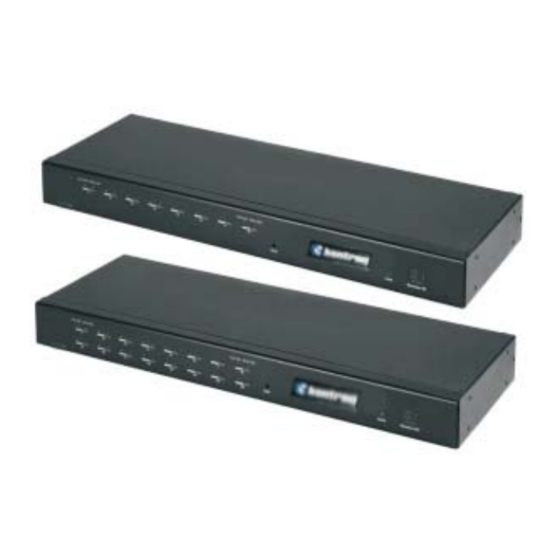
Cables Substandard cables may damage the connected devices or degrade overall performance. For optimum signal integrity and to simplify the layout, we strongly recommend that you use the high quality Kontron Custom Cable sets described below: Kontron Part Number Function RMVS-C202 - .6 m ~ 2 Ft... - Page 29 RMVS-1U.XXXB and RMVS-1U.XXXC The RMVS-1U.XXXB and RMVS-1U.XXXC utilize the On Screen Display (OSD) to indicate KVM Status. Please refer to chapter 4 for a complete guild on how to use this function. RMVS-KVMS08A Front View POWER 1. Port LEDs The Port LEDs provide status information about their corresponding CPU Ports.
- Page 30 3. Power LED The Power LED lights to indicate that the KVMS08A is powered up and ready to operate. 4. Station ID LED The KVMS08A’s Station ID is displayed here. Since it is being attached to an Integrated Console Unit that has a Station ID of 01 the daisy chain installation of the KVMS08A will display a Station ID that corresponds to its place in the chain starting at 02.
-
Page 31: Rmvs-Kmvs16A Front View
RMVS-KVMS16A Front View POWER 1. Port LEDs The Port LEDs provide status information about their corresponding CPU Ports. There is one pair of LEDs for each Port. The one on the left is the LED; the one on the right On Line is the LED:... - Page 32 3. Power LED Lights to indicate that the KVMS16A is powered up and ready to operate. 4. Station ID LED The KVMS16A’s Station ID is displayed here. Since it is being attached to an Integrated Console unit that has Station ID of the daisy chain installation of the KVMS08A will display a Station ID that corresponds to its place in the chain starting at...
-
Page 33: Rmvs Kvm's Rear View
RMVS KVM Rear Views -1U.XXXB 8 Port Integrated Console Unit -1U.XXXC 16 Port Integrated Console Unit -KVMS08A 8 Port Stand Alone Cascading Unit -KVMS16A 16 Port Stand Alone Cascading Unit 1. Daisy Chain Ports When Daisy Chaining Units, the cables plug in here. The ports are Chain In, And Chain Out. - Page 34 3. Cable Tie Slot If you want to use a cable tie to gather the cables together, you can run it through this slot to attach it to the unit. ( not provided on the Integrated Console Units) 4. Power Jack The power adapter cable plugs in here.
- Page 35 Notes: 1-12 RMVS-1U RMVS KVM Switch User’s Guide...
-
Page 36: Chapter 2 Installation
Chapter 2. Installation This chapter explains how to connect up your installation — from a basic Single Stage arrangement to a complete daisy chained configuration. Before you Begin 1. Make sure that power to all the devices you will be connecting up have been turned off. -
Page 37: Daisy Chaining
3. Plug the power adapter cable into the RMVS-1U.XXXB/C Power Jack, then plug the power adapter into an AC power source. 4. Turn on the power to the computers. Daisy Chaining To control even more computers, up to 31 additional switches can be daisy chained down from the first unit. - Page 38 Cables 2. Use a daisy chain cable set (described in the section, p. 1-5), to connect the Chain Out port of the -1U.XXXB/C to the Chain In port of the child switch (Console Station Out to Second Station In, Second Station Out to Third Station In, etc.). Chain In Note: You cannot use the...
- Page 39 Not Used RMVS-1U RMVS KVM Switch User’s Guide...
-
Page 40: Hot Plugging
Hot Plugging The RMVS KVM’s supports hot plugging - components can be removed and added back into the installation by unplugging their cables from the ports without the need to shut the unit down. In order for hot plugging to work properly, however, the procedures described below must be followed: Switching Station Positions: You can switch station positions by simply unplugging from the old... -
Page 41: Port Id Numbering
Port ID Numbering Each CPU port on a Master View installation is assigned a unique Port ID. Station Number The Port ID is made up of two parts: a two-digit , and a two-digit Port Number Station Number - reflects the switch’s position in the daisy chain sequence. -
Page 42: Chapter 3 Hotkey Operation
Chapter 3. Hotkey Operation This chapter details the concepts and procedures involved in the Hotkey operation of your RMVS KVM System installation. Hotkey Port Access Hotkey port access allows you to provide KVM focus to a particular computer directly from the keyboard. The RMVS KVM System Provides the following Hotkey port access features: Selecting the Active Port Auto Scanning... -
Page 43: Selecting The Active Port
When Hotkey Mode is active: The Caps Lock and Scroll Lock LEDs flash in succession. They stop flashing and revert to normal status when you exit Hotkey Mode. A Command Line appears on the monitor’s screen. The command line prompt is the word and appears in yellow text on a Hotkey: blue background. -
Page 44: Auto Scanning
Auto Scanning Auto Scan automatically switches among all accessible CPU Ports at regular intervals, so that the operator can monitor their activity without having to switch among them manually. (See of the OSD Scan/Skip Mode function, p. 4-7 for information regarding accessible ports.) F3 SET Setting the Scan Interval: The amount of time Auto Scan dwells on each port is set with the... - Page 45 Invoking Auto Scan: To start Auto Scanning, key in the following Hotkey combination: 1. Invoke Hotkey Mode (see p. 3-1). 2. Press You automatically exit Hotkey Mode, and enter Auto Scan Mode. The KVM focus switches among the accessible computers at regular intervals.
-
Page 46: Skip Mode
Skip Mode Skip Mode allows you to switch between computers in order to monitor them manually. Unlike Auto Scanning, which automatically switches after a fixed interval, you can dwell on a particular port for as long or as little as you like. To invoke Skip Mode, key in the following Hotkey combination: 1. -
Page 47: Hotkey Beeper Control
Hotkey Beeper Control The Beeper (see Activate Beeper, p. 4-9) can be Hotkey toggled On and Off. To toggle the Beeper, key in the following Hotkey combination: 1. Invoke Hotkey Mode (see p. 3-1). 2. Press After you press , the Beeper toggles On or Off. The Command Line displays for one second;... -
Page 48: Chapter 4 Osd Operation
Chapter 4. OSD Operation This chapter provides a complete description of the procedures involved in the OSD (On Screen Display) operation of your RMVS KVM System installation. OSD Operation OSD Overview The On Screen Display (OSD) is a menu driven method to handle computer control and switching operations. - Page 49 When you invoke the OSD, a screen similar to the one below appears: F1:GOTO F3:SET F5:SKP F7:SCAN F2:LIST F4:ADM F6:BRC F8:LOUT ADMINISTRATOR LIST:ALL SN PN NAME 01 14 INTL.CO. 1 01 15 INTL.CO. 2 01 16 INTL.CO. 3 FAX SERVER 1 FAX SERVER 2 WEB SERVER 1 WEB SERVER 2...
-
Page 50: Osd Navigation
Navigation To dismiss the menu, and deactivate OSD, Click the at the upper right corner of the OSD Window; or press [Esc] F8 at the top of the Main Screen, or press To Logout, Click [F8] Or click the symbol at the upper right corner of the OSD screen. To move up or down through the list one line at a time, Click the ) or use the Up and Down Up and Down Triangle symbols (... -
Page 51: Osd Functions
OSD functions are used to configure and control the OSD. For example, Functions you can: rapidly switch to any port; scan selected ports only; limit the list you wish to view; designate a port as a Quick View Port; create or edit a port name;... - Page 52 F2 LIST: The LIST function lets you broaden or narrow the scope of which ports the OSD displays (lists) on the Main Screen. Many of the OSD functions only operate on the computers that have been selected for listing on the Main Screen with this function.
- Page 53 F3 SET: This function allows the Administrator and each User to set up his own working environment. A separate profile for each is stored by the OSD and is activated according to the Username that is provided during Login. To change a setting: 1.
- Page 54 (F3 SET: continued) Setting Function PORT ID Selects how the Port ID is displayed: the Port Number alone DISPLAY (PORT NUMBER); the Port Name alone (PORT NAME); or MODE the Port Number plus the Port Name (PORT NUMBER + PORT NAME). The default is PORT NUMBER + PORT NAME).
- Page 55 F4 ADM: F4 is an Administrator only function. It allows the Administrator to configure and control the overall operation of the OSD. To change a setting Double Click it; or use the Up and Down Arrow Keys to move the highlight bar to it then press [Enter] After you select an item, a submenu with further choices for you to select from appears.
- Page 56 (F4 ADM: continued) Setting Function EDIT PORT To help remember which computer is attached to a particular NAMES port, every port can be given a name. This function allows the Administrator to create, modify, or delete port names. To Edit a port name: 1.
- Page 57 (F4 ADM: continued) Setting Function SET QUICK This function lets the Administrator select which Ports to VIEW PORTS include as Quick View ports. To select/deselect a port as a Quick View Port, Double Click the port you want, or use the Navigation Keys to move the highlight bar to it, then press [Enter].
- Page 58 (F4 ADM: continued) Setting Function RESET If you change the position of one of the Stations in the daisy STATION IDS chain, the OSD settings will no longer correspond to the new situation. This function directs the OSD to rescan the Station positions of the entire installation and updates the OSD so that the OSD Station information corresponds to the new physical layout.
- Page 59 F5 SKP: This function enables you to easily skip backward or forward - switching the console focus from the currently active computer port to the previous or next available one. The selection of computers to be available for Skip Mode switching is made with the setting under the Scan/Skip Mode...
- Page 60 F6 BRC: F6 is an Administrator only function. When this function is in effect, commands sent from the console are broadcast to all available computers on the installation. This function is particularly useful for operations that need to be performed on multiple computers, such as performing a system wide shutdown, installing or upgrading software, etc.
- Page 61 F7 SCAN: The SCAN function allows you to automatically switch among the available computers at regular intervals so that you can monitor their activity without having to take the trouble of switching manually. The selection of computers to be included for Auto Scanning is made with the setting under the Scan/Skip Mode...
- Page 62 F8 LOUT: This function logs you out of OSD control of the computers, and blanks the Console screen. After using this function you must log in all over again to regain access to the OSD. This is different from simply pressing when you are at the [Esc] Main Screen to deactivate the OSD, where all you have to do to...
- Page 63 Notes: 4-16 RMVS-1U RMVS KVM Switch User’s Guide...
-
Page 64: The Firmware Upgrade Utility
As new firmware revisions become available, new firmware upgrade packages are posted on our web site: Http://www.Kontron.com Check the web site regularly to find the latest packages and information relating to them. RMVS-1U RMVS KVM Switch User’s Guide... -
Page 65: Before You Begin
Before You To prepare for the firmware upgrade, do the following: Begin 1. From a computer that is not part of your KVM installation go to our Internet support site and choose the model name that relates to your device to get a list of available Firmware Upgrade Packages. 2. -
Page 66: Performing The Upgrade
Performing the Upgrade Starting the To upgrade your firmware: Upgrade 1. Run the downloaded Firmware Upgrade Package file - either by double clicking the file icon, or by opening a command line and entering the full path to it. The Firmware Upgrade Utility screen appears: Welcome 2. - Page 67 3. Click Next to continue. The Firmware Upgrade Utility main screen appears: The Utility inspects your installation. All the devices capable of panel. being upgraded by the package are listed in the Device List 4. As you select a device in the list, its description appears in the panel.
- Page 68 5. After you have made your device selection(s), Click Next perform the upgrade. If you enabled , the Utility compares the Check Firmware Version device’s firmware level with that of the upgrade files. If it finds that the device’s version is higher than the upgrade version, it brings up a dialog box informing you of the situation and gives you the option to Continue or Cancel.
-
Page 69: Upgrade Succeeded
Upgrade After the upgrade has completed, a screen appears to inform you that Succeeded the procedure was successful: Click to close the Firmware Upgrade Utility. Finish RMVS-1U RMVS KVM Switch User’s Guide... -
Page 70: Upgrade Failed
Upgrade If the upgrade failed to complete successfully a dialog box appears Failed asking if you want to retry. Click to retry. If you Click , the Upgrade Failed screen appears: Click to close the Firmware Upgrade Utility. See the next Cancel section, , for how to proceed. -
Page 71: Firmware Upgrade Recovery
Firmware Upgrade Recovery There are basically three conditions that call for firmware upgrade recovery: When you invoke Firmware Upgrade Mode (see p. 5-2), but decide not to proceed with the upgrade. When the Mainboard firmware upgrade fails. When the I/O firmware upgrade fails. To perform a firmware upgrade recovery, do the following: 1. -
Page 72: Rmvs Kvm's - Connection Tables
Appendix This appendix provides specifications and other technical information regarding the RMVS KVS System. RMVS KVM System - Connection Tables The following tables indicate the relationship between the number of RMVS KVM units and the number of computers that they control: RMVS-1U.XXXB RKs Computers Computers... -
Page 73: Osd Factory Default Settings
RMVS-1U.XXXC RKs Computers RKs Computers RKs Computers RKs Computers And Cascading RMVS-KVMS16A 1 - 16 129 - 144 257 - 272 385 - 400 Units 17 - 32 145 - 160 273 - 288 401 - 416 33 - 48 161 - 176 289 - 304 417 - 432... -
Page 74: Clear Login Information
Clear Login Information If you are unable to perform an Administrator login (because the Username and Password information has become corrupted, or you have forgotten it, for example), you can clear the login information with the following procedure: 1. Power off the switch and remove its housing. 2. -
Page 75: Specifications
Specifications Function -KVMS16A RMVS -KVMS08A Computer Direct Connections 256 (via Daisy Chain) 512 (via Daisy Chain) Port Selection OSD (On Screen Display); Hotkeys LEDs On Line 8 (Orange) 16 (Orange) Selected 8 (Green) 16 (Green) Power 1 (Blue) 2 x 7 Segments Console Keyboard 1 x 6 pin mini DIN F... -
Page 76: Rack Mounting
Rack Mounting The RMVS-KVMS08A/-KVMS16A can be mounted in a 1U system rack. For convenience and flexibility, the mounting brackets can screw into either the front or the back of the unit so that it can attach to the front or the back of the rack.To rack mount the unit do the following: 1. -
Page 77: Troubleshooting
Troubleshooting Symptom Possible Cause Action Erratic behavior. Unit not receiving Check that the Power Adapter that enough power. was supplied with the unit is plugged in and functioning properly. Mouse and/or Improper mouse Unplug the cable(s) from the console Keyboard not and/or keyboard port(s), then plug it/them back in. - Page 78 Index G - H Activate Beeper....4-9 ADM ......4-8 GOTO .
- Page 79 Reset Station IDs ....4-11 Restore Default Values ....4-9 LIST ......4-5 Logout .
- Page 80 EN 60950:1992 Safety of Information Technology Equipment The technical documentation required to demonstrate this product meets the requirements of the EMC Directive and the Low Voltage Directive has been compiled by Kontron and is available for inspection by the relevant enforcement author ities.
Need help?
Do you have a question about the RMVS KVM Series and is the answer not in the manual?
Questions and answers