Table of Contents
Advertisement
Quick Links
Advertisement
Table of Contents

Related Manuals for Kontron CP6930-1


Summary of Contents for Kontron CP6930-1
- Page 1 User Guide CP6930-1 Document Revision 1.1 Date: August, 2016 www.kontron.com...
-
Page 2: Revision History
Disclaimer Copyright © 2016 Kontron AG. All rights reserved. All data is for information purposes only and not guaranteed for legal purposes. Infor- mation has been carefully checked and is believed to be accurate; however, no responsibility is assumed for inaccuracies. Kontron and the Kontron logo and all other trademarks or registered trademarks are the property of their respective owners and are recognized. -
Page 3: Table Of Contents
1.3.9 Shock......................5 1.3.10 Safety ......................6 1.3.11 Electromagnetic Compatibility ................6 1.3.12 Reliability ..................... 6 1.3.13 WEEE......................6 1.3.14 RoHS ......................6 1.3.15 Lead-free...................... 6 Software Support ....................7 Installation......................... 9 Safety Requirements.................... 9 CP6930-1 Initial Installation Procedures..............10 www.kontron.com... - Page 4 4.2.4 Routing Package MIBs ................... 38 4.2.5 QoS Package MIBs ..................38 4.2.6 Multicast package MIBs ................. 38 4.2.7 Security MIBs ....................39 4.2.8 Kontron Private MIBs ..................39 Bootloader ...................... 41 4.3.1 Power On Self Test ..................41 4.3.2 Bootloader Shell options ................42 IPMI Firmware ....................
- Page 5 CP6930-1 User Guide 4.4.3 Board FRU Information .................. 58 Firmware Administration ..................58 4.5.1 Updating Firmware ..................60 4.5.2 Updating IPMI ..................... 61 Thermal Considerations ....................62 Thermal Monitoring ................... 62 Thermal Regulation ................... 63 Airflow......................64 Power Considerations....................66 System Power....................
- Page 6 Voltage Sensors ..................... 19 Table 3-3: Write protection level set by FWPD and EWP ............20 Table 3-4: Non-volatile memories on the CP6930-1 ............. 20 Table 3-5: SFP and SFP+ Connector .................. 21 Table 3-6: Front RJ45 Ethernet Connector ................. 22 Table 3-7: Front RS232 ....................
- Page 7 List of Figures Figure 3-1: Functional Block Diagram CP6930-1 ............... 15 Figure 3-2: Front Panel of the CP6930-1 .................. 21 Figure 3-3: Jumper Block Pinning ..................24 Figure 5-1: Temperature Sensor Location ................63 Figure 5-2: Maximum PCB3 temperature versus airflow............... 64 Figure 5-3: Impedance Curve - pressure versus airflow ...............
-
Page 8: Proprietary Note
This document contains information proprietary to Kontron. It may not be copied or transmitted by any means, disclosed to others, or stored in any retrieval system or media without the prior written consent of Kontron AG or one of its authorized agents. -
Page 9: Safety Instructions
It was also designed for a long fault-free life. However, the life expectancy of your product can be drastically reduced by improper treatment during unpacking and installation. Therefore, in the interest of your own safety and of the correct operation of your new Kontron product, you are requested to conform with the following guidelines. - Page 10 CP6930-1 User Guide Laser Lights Laser light from fiber-optic transmission cables and components can damage your eyes. The laser components plugged into the switch are Class 1 laser components. Class 1 laser is considered incapable of pro- ducing damaging radiation levels during normal operation or mainte- nance.
-
Page 11: General Instructions On Usage
TWO YEAR LIMITED HARDWARE WARRANTY ing. However, no other warranties that may be granted or implied by anyone on behalf of Kontron are valid unless the con- sumer has the express written consent of Kontron. -
Page 12: Introduction
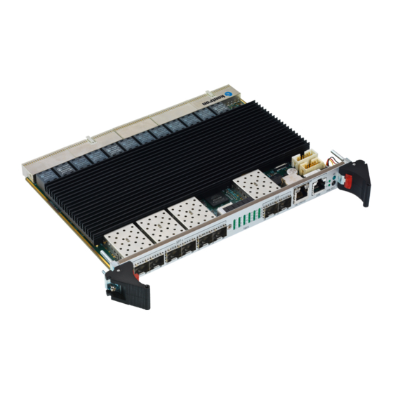
Introduction Product Overview The CP6930-1 is a Standard Fabric 6U CompactPCI Gigabit Ethernet Switch with 24 channels providing Layer 2 and Layer 3 switching/routing functions in a PICMG 2.16 compliant form factor. The product features 24 x 1000Base-T ports to the PICMG 2.16 backplane plus 8 x 1GbE front panel Interfaces via standard MSA SFP+ cages. - Page 13 Metalwork compliant to PICMG® 2.0 6U/4HP (233.35 mm by 160 mm) / (20.32 mm typ.) • Optionally NV Memories can be hardware protected Note... SFP or SFP+ modules are not included with the CP6930-1. An application note with a list of modules successfully operated in the CP6930-1 is available upon request. www.kontron.com...
-
Page 14: General Compliances
The IO modules provide additional GbE switch ports and out-of-band management access via RS232. With an appropriate backplane, all switch ports of the CP6930-1 that connect to the backplane can be accessed using the module. The following modules supporting the CP6930-1 are available:... -
Page 15: Technical Specification
Supply voltages are: • 5.0 Volt • 3.3 Volt • 5.0 Volt IPMB_PWR Power consumption of the CP6930-1: • Management only (handle open): <1W • Idle (no links): 35W • Maximum (full traffic/load): 59W No external power sequencing is required. -
Page 16: Humidity
CP6930-1 User Guide 1.3.5 Humidity The board is designed to meet Bellcore GR63, Section 4.1 • Operating: 93% (non-condensing) at 40°C • Non-Operating: 5%-95% (non-condensing) at 40°C 1.3.6 Altitude The board is designed to meet the following requirements: • Operating: 15000 ft, additional cooling might be required above 6000ft •... -
Page 17: Safety
CP6930-1 User Guide 1.3.10 Safety The board is designed to meet or meets the following requirements: • UL 60950, 3rd edition (US and Canada) • EN 60950 (Europe) • LVD 73/23/EEC (Europe) • Denan Law (Japan Safety) The board is designed to meet the following flammability requirement (as specified in Telcordia GR-63-CORE): •... -
Page 18: Software Support
CP6930-1 User Guide Software Support The following table contains information related to software supported b y the CP6930-1. Table 1-2: CP6930-1 Software Specification CP6930-1 SPECIFICATIONS • General Reliable field upgrades for all software components • Dual boot images with roll-back capability •... - Page 19 • Support for retrieving and installing multiple configurations • Support for startup configurations based on the cPCI SGA/GA (Shelf Geograph- ical Address/Geographical Address), see CP6930-1 CLI Reference Manual, chapter „AutoInstall Commands“ • Supported MIBS For a list of supported MIBs, see chapter “Supported MIBs” on page 36 •...
-
Page 20: Installation
Safety Requirements The following safety precautions must be observed when installing or operating the CP6930-1. Kontron assumes no respon- sibility for any damage resulting from failure to comply with these requirements. Warning Due care should be exercised when handling the board due to the fact that the heat sink can get very hot. -
Page 21: Cp6930-1 Initial Installation Procedures
CP6930-1 User Guide CP6930-1 Initial Installation Procedures The following procedures are applicable only for the initial installation of the CP6930-1 in a system. Procedures for stan- dard removal and hot swap operations are found in their respective chapters. To perform an initial installation of the CP6930-1 in a in a system proceed as follows: 1. -
Page 22: Standard Removal Procedures
Chapter 4. Quick Start This section gives instructions for (initially) accessing the CLI (Command Line Interface) of the CP6930-1 using either in- band access via the ethernet fabric or the out-of-band management interfaces (serial port or Fast Ethernet) accessible from the front plate serial connector or via an appropriate RIO module. -
Page 23: Out-Of-Band Cli Access
Fast Ethernet Serviceport The Gigabit Ethernet serviceport on the CP6930-1 front plate has no IP address set by default, it is necessary to assign an IP address statically or enable dhcp on the serviceport. Because the required configuration steps are done in the CLI, an initial access using the serial port is required. -
Page 24: In-Band Cli Access
In-Band CLI Access The GbE switch network port (in-band management access) on the CP6930-1 has no IP address set by default, it is necessary to assign an IP address either statically or by using DHCP to the network port. Because the required configuration steps are done in the CLI, an initial access using the serial port is required. - Page 25 To access the CLI via Fast Ethernet networkport, open a telnet connection to the configured IP address, port 23. It might make sense to separate the management network from the data path by setting appropriate VLANs For additional information on the system configuration, refer to the CP6930-1 CLI Reference Manual. www.kontron.com...
-
Page 26: Functional Description
CP6930-1User Guide Functional Description The board is composed of the following building blocks: • Ethernet Infrastructure • Unit Computer and Memory • IPMI • Power Supply Figure 3-1: Functional Block Diagram CP6930-1 www.kontron.com... -
Page 27: Ethernet Infrastructure
0/21 Node Link 21 10/100/1000 Mbps 0/22 Node Link 22 10/100/1000 Mbps 0/23 Node Link 23 10/100/1000 Mbps 0/24 Fabric Interlink F 10/100/1000 Mbps 0/25 SFP 1 10/100/1000 Mbps 0/26 SFP 2 10/100/1000 Mbps 0/27 Unit Computer 1000 Mbps www.kontron.com... - Page 28 0/33 SFP+ 6 1/10 Gbps The CP6930-1 supports SFP and SFP+ fabric switch uplinks to the front panel. The SFPs uplink ports are according the Small Form-factor Pluggable (SFP) Transceiver Multi-Source Agreement (MSA), Sept. 14th, 2000. Note... SFP or SFP+ modules are not included with the CP6930-1. An application note with a list of modules successfully operated in the CP6930-1 is available upon request.
-
Page 29: Unit Computer And Memory
Real Time Clock with integrated oscillator, powered by a capacitor with up to 1 week of back up power IPMI The CP6930-1 board supports an intelligent hardware management system, based on the Intelligent Platform Management Interface Specification 1.5. The hardware management system provides the ability to manage the power, cooling and inter- connect needs of intelligent devices, to monitor events and to log events to a central repository intelligent FRU (Field Replaceable Unit). -
Page 30: Ipmb Interface
3.3.1 IPMB Interface The CP6930-1 IPMI firmware implements the two independent IPMB-0 and IPMB-1 interfaces. The IPMB-0 can be switched to a redundant mode by aggregating the physical IPMB-0 and IPMB-1 lines together to one sin- gle logical IPMB-0. In redundant mode, command retries are send over the second physical line if the command timed out using the first line. -
Page 31: Write Protection Feature
CP6930-1User Guide Write Protection Feature The CP6930-1 supports hardware driven write protection for all non-volatile memory devices. Depending on the device, the protection is implemented either by a dedicated write protection signal, by disabling the write enable signal, or the whole interface. -
Page 32: Board Interfaces
CP6930-1User Guide Board Interfaces Figure 3-2: Front Panel of the CP6930-1 3.5.1 Front Panel Ports • 8x 1GBase-X uplinks (SFP connector cages), 6 of them configurable for 10GBase-X operation using SFP+ optical trans- ceivers • SGMII support for 'Copper-SFPs' in 2 of the 8 front panel uplink ports (providing 10/100/1000Base-T modes of oper- ation) •... -
Page 33: Table 3-6: Front Rj45 Ethernet Connector
CP6930-1User Guide Table 3-6: Front RJ45 Ethernet Connector Contact BI_DA+ BI_DA- BI_DB+ BI_DC+ BI_DC- BI_DB- BI_DD+ BI_DD- Link/Activity Speed Table 3-7: Front RS232 Direction Signal www.kontron.com... -
Page 34: Front Panel Leds
Green Link/Activity LED for the CPU 10/100/1000Base-T Management port: • link down • link up but no activity • Blinking link up and activity Amber/Grenn Speed LED for the CPU 10/100/1000Base-T Management port: • 10Base-T • On (amber) 100Base-Tx • On (green) 1000Base-T www.kontron.com... -
Page 35: Front Panel Switches
CP6930-1User Guide 3.5.2.1 Health LED (Green LED) The CP6930-1 Switch Board supports a Health LED mounted on the front panel. The following states are possible: Table 3-9: Health LED state LED state Description Normal state when board is in operation. -
Page 36: Backplane Connectors
For accessing the GbE interfaces signals on connectors J3, J4 and J5 with a rear I/O module, a special backplane is neces- sary. The CP6930-1 is compatible with all standard 6U CompactPCI passive backplanes with rear I/O support on the system slot. -
Page 37: Table 3-12: Connector J2 Pinout
CP6930-1User Guide 3.5.5.2 J2 Connector • Geographical Address • IPMB 1 • ALERT# Table 3-12: Connector J2 Pinout Row A Row B Row C Row D Row E Row F CPCI_GA[4] CPCI_GA[3] CPCI_GA[2] CPCI_GA[1] CPCI_GA[0] IPMB1_SDA IPMB1_SCL IPMB_ALERT# www.kontron.com... -
Page 38: Table 3-13: Connector J3 Pinout
FL_DA5- FL_DC5+ FL_DC5- FL_DB5+ FL_DB5- FL_DD5+ FL_DD5- FL_DA4+ FL_DA4- FL_DC4+ FL_DC4- FL_DB4+ FL_DB4- FL_DD4+ FL_DD4- FL_DA3+ FL_DA3- FL_DC3+ FL_DC3- FL_DB3+ FL_DB3- FL_DD3+ FL_DD3- FL_DA2+ FL_DA2- FL_DC2+ FL_DC2- FL_DB2+ FL_DB2- FL_DD2+ FL_DD2- FL_DA1+ FL_DA1- FL_DC1+ FL_DC1- FL_DB1+ FL_DB1- FL_DD1+ FL_DD1- www.kontron.com... -
Page 39: Table 3-14: Connector J4 Pinout
FL_DD21- FL_DA22+ FL_DA22- FL_DC22+ FL_DC22- FL_DB22+ FL_DB22- FL_DD22+ FL_DD22- FL_DA23+ FL_DA23- FL_DC23+ FL_DC23- FL_DB23+ FL_DB23- FL_DD23+ FL_DD23- Key Area RTM_TXD# RTM_RXD# Note... RTM_TXD# (driven by CP6930-1) and RTM_RXD# (driven by RIO module) are the two-pin RS232 rear I/O interface. www.kontron.com... -
Page 40: Table 3-15: Connector J5 Pinout
FL_DA13- FL_DC13+ FL_DC13- FL_DB13+ FL_DB13- FL_DD13+ FL_DD13- FL_DA12+ FL_DA12- FL_DC12+ FL_DC12- FL_DB12+ FL_DB12- FL_DD12+ FL_DD12- FL_DA11+ FL_DA11- FL_DC11+ FL_DC11- FL_DB11+ FL_DB11- FL_DD11+ FL_DD11- FL_DA10+ FL_DA10- FL_DC10+ FL_DC10- FL_DB10+ FL_DB10- FL_DD10+ FL_DD10- FL_DA9+ FL_DA9- FL_DC9+ FL_DC9- FL_DB9+ FL_DB9- FL_DD9+ FL_DD9- www.kontron.com... -
Page 41: Software Description
This manual only describes bootloader, its self tests and IPMI Firmware and introduces the update procedure. For additional information of system configuration using CLI commands refer to documentation “CP6930-1 CLI Reference Manual”. -
Page 42: Fastpath Switching
CP6930-1 User Guide • RFC 3415 — View-based Access Control Model • RFC 3416 — Version 2 of SNMP Protocol Operations • RFC 3417 — Transport Mappings • RFC 3418 — Management Information Base (MIB) for the Simple Network Management Protocol (SNMP) •... - Page 43 CP6930-1 User Guide • IEEE 802.3ab — 1000Base-T • IEEE 802.3ac — VLAN tagging • IEEE 802.3ad — Link aggregation • IEEE 802.3ae — 10GbE • IEEE 802.3x — Flow control • ANSI/TIA-1057 — LLDP-MED • GARP — Generic Attribute Registration Protocol: clause 12, 802.1D-2004 •...
-
Page 44: Fastpath Routing
CP6930-1 User Guide • RFC 791 — IP • RFC 792 — ICMP • RFC 793 — TCP • RFC 826 — Ethernet ARP • RFC 894 — Transmission of IP Datagrams over Ethernet Networks • RFC 896 — Congestion Control in IP/TCP Networks •... -
Page 45: Fastpath Ipv6 Routing
CP6930-1 User Guide • RFC 3046 — DHCP/BOOTP relay • RFC 3101 — The OSPF “Not So Stubby Area” (NSSA) option • RFC 3107 — Carrying label information in BGP-4 • RFC 3137 — OSPF Stub Router Advertisement • RFC 3623 — Graceful OSPF Restart •... -
Page 46: Fastpath Quality Of Service
CP6930-1 User Guide 4.1.5 FASTPATH Quality of Service DiffServ • RFC 2474 — Definition of the differentiated services field (DS Field) in the IPv4 and IPv6 headers • RFC 2475 — An architecture for differentiated services • RFC 2597 — Assured forwarding PHB group •... -
Page 47: Fastpath Multicast
CP6930-1 User Guide 4.1.6 FASTPATH Multicast Core Features • RFC 1112 — Host extensions for IP multicasting • RFC 2236 — IGMP v2 • RFC 2365 — Administratively scoped boundaries • RFC 2710 — MLDv1 • RFC 3376 — IGMPv3 •... -
Page 48: Switching Package Mibs
CP6930-1 User Guide • RFC 3417 - SNMPV2-TM • RFC 3415 - View-based Access Control Model for SNMP MIB • RFC 3411 - SNMP-FRAMEWORK-MIB • RFC 3412 - SNMP-MPD-MIB • RFC 3413 - SNMP-NOTIFICATION-MIB • RFC 3413 - SNMP-PROXY-MIB (initial revision published as RFC 2273) •... -
Page 49: Routing Package Mibs
CP6930-1 User Guide • RFC 3291 — Textual Conventions for Internet Network Addresses • RFC 3635 — Etherlike MIB • RFC 3636 — IEEE 802.3 Medium Attachment Units (MAUs) MIB • RFC 4022 — Management Information Base for the Transmission Control Protocol (TCP) •... -
Page 50: Security Mibs
IEEE 802.1X MIB (IEEE 8021-PAE-MIB 2004 Revision) 4.2.8 Kontron Private MIBs For the CP6930-1, Kontron provides several MIBs in addition to the Standard MIBs (see “Supported MIBs” on page 36) that allows to use SNMP for configuration of : •... - Page 51 CP6930-1 User Guide • CPU load • Suppress MAC learning • Fast Reload • Memory Usage • L2 port bridge • Port blocking mode • BPDU forwarding • Suppress MAC learning • kex_oem • Customer specific information • OEM serial number •...
-
Page 52: Bootloader
CP6930-1 User Guide Bootloader On the CP6930-1 CPCI Ethernet Switch board, the bootloader 'u-boot' (universal bootloader) is used. The bootloader ini- tializes the main components of the board like Unit Computer, DDR2 RAM, serial lines etc. for operation and performs a power on self test (POST). -
Page 53: Bootloader Shell Options
CP6930-1 User Guide 4.3.2 Bootloader Shell options The boot process can be interrupted by entering the bootstopkey phrase “stop”. This will open a bootloader shell session. Entering “?” provides a list of possible built-in commands, “printenv” provides a list of current environment settings. The bootloader shell can be used to customize boot options and system startup by changing some of its environment variables. - Page 54 CP6930-1 User Guide Table 4-3: Bootloader Shell Options (Continued) Name Type Description Stores the POST result postresult Auto 0 – no POST error occurred 1 – a POST error occurred recover_flash Script Command script that is executed when the onboard flash is corrupted 0 –...
-
Page 55: Ipmi Firmware
CP6930-1 User Guide ENV: Using default environment Any changes of the environment can be cleared using the ‘clear_env’ script (provided that ‘clear_env’ itself was not changed): => run clear_env IPMI Firmware The PPC communicates with the Peripheral Manager (PM) using the Keyboard Controller Style (KCS) interface. The boot- loader is able to communicate with the PM, e.g. -
Page 56: Supported Ipmi Commands
CP6930-1 User Guide 4.4.1 Supported IPMI Commands 4.4.1.1 Standard Commands Part of the command list in IPMI specification 2.0 M = mandatory, O = optional Table 4-4: Standard Commands IPMI 2.0 Spec. Support on Command NetFn section CP6930-1 IPM Device “Global” Commands Get Device ID 20.1... - Page 57 CP6930-1 User Guide Table 4-4: Standard Commands (Continued) IPMI 2.0 Spec. Support on Command NetFn section CP6930-1 Get User Access 22.27 O / No Set User Name 22.28 O / No Get User Name 22.29 O / No Set User Password 22.30...
- Page 58 CP6930-1 User Guide Table 4-4: Standard Commands (Continued) IPMI 2.0 Spec. Support on Command NetFn section CP6930-1 Get Sensor Reading Factors 35.5 O / No Set Sensor Hysteresis 35.6 O / No Get Sensor Hysteresis 35.7 O / No Set Sensor Threshold 35.8...
-
Page 59: Table 4-5: Hpm.1 Commands
HPM.1 Get Upgrade Status HPM.1 Activate Firmware HPM.1 Query Self-Test Results HPM.1 Query Rollback Status HPM.1 Initiate Manual Rollback HPM.1 4.4.1.2 Kontron OEM Commands and Extensions Table 4-6: Kontron OEM Commands Command NetFn OemApSetNvParam OemApFormatStorage OemApRefreshExternUpdatedSensor OemApSetManufacturingDate OemApGetManufacturingDate OemApGetReleaseInfo OemApGetFirmwareCapabilities... - Page 60 CP6930-1 User Guide Get Device ID Command with OEM Extensions NetFn Get Device ID command with OEM extensions App = 06h Byte Data Field Request Data Completion Code Device ID, returned as 0fh. Device Revision. [7] returned as 1 = device provides device SDRs [6..4] Reserved.
- Page 61 CP6930-1 User Guide oemApSetNvParam NetFn oemApSetNvParam OEM = 3Eh Byte Data Field Pass Code 0: ~’K’ (0xBA) Pass Code 1: ~’o’ (0x90) 1...4 Pass Code 2: ~’n’ (0x91) Pass Code 3: ~’t’ (0x8B) Command Flag: [7..2] reserved [1] 1=set values, 0= get values...
- Page 62 CP6930-1 User Guide Oem Refresh Extern Updated Sensor NetFn OemRefreshExternUpdatedSensor OEM = 3Eh Byte Data Field Pass Code 0: ~’K’ (0xBA) Pass Code 1: ~’o’ (0x90) 1...4 Pass Code 2: ~’n’ (0x91) Request data Pass Code 3: ~’t’ (0x8B) 4..N...
- Page 63 CP6930-1 User Guide Byte Data Field Pass Code 0: ~’K’ (0xBA) Pass Code 1: ~’o’ (0x90) Request data 1...4 Pass Code 2: ~’n’ (0x91) Pass Code 3: ~’t’ (0x8B) Completion Code Response data 2...4 Manufacturing Date OemApGetReleaseInfo This command returns firmware related release information.
- Page 64 CP6930-1 User Guide Byte Data Field Pass Code 0: ~’S’ Pass Code 1: ~’1’ Request data Pass Code 2: ~’7’ Pass Code 3: ~’0’ Pass Code 4: ~’1’ Completion Code. Response data 2..19 Firmware capabilities vector OemApSetFirmwareCapabilities This command sets the firmware capabilities vector.
-
Page 65: Board Sensors
(SDRR) of the whole rack if the SDRR is generated. The generation of the SDRR has always to be done new after adding or subtracting any board to or from the rack. For OEM (Kontron) specific sensor types and reading types in the following table please refer to the next chapter. Table 4-7:... - Page 66 CP6930-1 User Guide Table 4-7: Sensor List (Continued) Sensor Number / ID Sensor Type (CODE) Event Type Code / Event Offsets string Event Type: 6Fh (Sensor Specif ic) Refer to IPMI v1.5 5 / SEL State 10h (Event Logging Disabled)
- Page 67 CP6930-1 User Guide Table 4-7: Sensor List (Continued) Sensor Number / ID Sensor Type (CODE) Event Type Code / Event Offsets string 29 / Vcc1.2vCORE 02h (Voltage) Event Type: 01h (Threshold) 30 / Vcc1.2v 02h (Voltage) Event Type: 01h (Threshold) 31 / Vcc1.0v...
-
Page 68: Table 4-8: Temperature Sensor Thresholds [°C]
CP6930-1 User Guide 4.4.2.2 Sensor Thresholds Following tables show sensor thresholds for temperature, voltage and current sensors. Table 4-8: Temperature Sensor Thresholds [°C] SENSOR Number/ ID Lower criti- Lower non Upper non Upper criti- Upper Non Nominal string critical critical... -
Page 69: Board Fru Information
Shown values are examples. Firmware Administration A running CP6930-1 system requires – after the bootloader has passed control to the kernel – the kernel itself, the root file system (initrd) and the FASTPATH switching application. These software components make up the CP6930-1 firmware. -
Page 70: Table 4-10: On-Board Nor Flash Partition Scheme (128 Mb)
Therefore each boot monitor uses two flash sectors (partition mtd2) for storing its environment and redundant copy. A complete software release for the CP6930-1 consists of three files: • CP6930-1-update-<release>.pkg •... -
Page 71: Updating Firmware
The CLI commands described below are executed in the privileged mode of the CLI hierarchy, which is entered by executing the ‘enable’ command. Please refer to the “CP6930-1 CLI Reference Manual“ for more information regarding the CLI com- mands and the way to use them. -
Page 72: Updating Ipmi
CP6930-1 User Guide The image will be copied including the configuration settings currently stored for image 1 4.5.2 Updating IPMI Updating the IPMI firmware is done with the “copy” command. In case that the update procedure fails or the update image is corrupted, the PM will be able to restart by means of its rollback functionality. -
Page 73: Thermal Considerations
The complete list of sensors and their alarm thresholds can be found in chapter “Board Sensors” on page 54. As long as the temperature values stay below their upper critical threshold, all components on the CP6930-1 are considered to be operated within their specified temperature range. -
Page 74: Thermal Regulation
Temperature Sensor Location Thermal Regulation When developing applications using the CP6930-1, the system integrator must be aware of the overall system thermal requirements. A system chassis must be provided which satisfy these requirements. Measurements proofed that operation in worst case conditions (maximum ambient temperature of 68°C under maximum load) with sufficient air flow (i.e. -
Page 75: Airflow
Maximum PCB3 temperature versus airflow Airflow In order to allow system integrators to optimize environmental conditions for the CP6930-1, airflow measurements were performed. The pressure drop between inlet and outlet was measured and is shown in the following graph. Figure 5-3: Impedance Curve - pressure versus airflow www.kontron.com... -
Page 76: Figure 5-4: Airflow Distribution By Test Section
CP6930-1 User Guide The area between the front panel and the backplane connectors is divided into five zones. The following diagram shows the airflow distribution across those zones. Figure 5-4: Airflow Distribution by Test Section www.kontron.com... -
Page 77: Power Considerations
6.1.1 Baseboard The CP6930-1 baseboard itself has been designed for optimal power input and distribution. Still it is necessary to observe certain criteria essential for application stability and reliability. The board is supplied by the 3.3V and the 5.0V from the backplane. All supply voltages from the backplane are enabled with a predefined ramp-up time. -
Page 78: Power Supply Units
As the design of the CP6930-1 has been optimized for minimal power consumption, the power supply unit shall be stable even without minimum load. -
Page 79: Power Consumption
For example, if the +5V begins to decrease, +3.3V must decrease accordingly. This is required in order to pre- clude cross currents within the CP6930-1. Failure to comply with above may result in damage to the board or improper system operation. -
Page 80: Start-Up Currents
Max. Traffic 57.6 Start-up Currents The start-up currents of the CP6930-1 during the first 2-3 seconds after power has been applied (power-on or hot-swap insertion) are less than the maximum currents given in Table 6-3 for each of the variants. www.kontron.com... - Page 81 CP6930-1 User Guide CORPORATE OFFICES Europe, Middle East & Africa North America Asia Pacific Lise-Meitner-Straße 3-5 14118 Stowe Drive 17 Building,Block #1, ABP. 86156 Augsburg Poway, CA 92064-7147 188 Southern West 4th Ring Road Germany Beijing 100070, P.R.China Tel.: + 49 (0) 821 / 4086 01 Tel.: + 1 888 294 4558...
Need help?
Do you have a question about the CP6930-1 and is the answer not in the manual?
Questions and answers