
Related Manuals for Kontron CP6930-RM


Summary of Contents for Kontron CP6930-RM
- Page 1 » Kontron User's Guide « CP6930-RM Document Revision 1.0 Document ID: CP6930-RM Issue Date: October 2011 If it's embedded, it's Kontron. www.kontron.com...
-
Page 2: Revision History
© 2011 Kontron, an International Corporation. All rights reserved. The information in this user's guide is provided for reference only. Kontron does not assume any liability arising out of the application or use of the information or products described herein. This user's guide may contain or reference information and products protected by copyrights or patents and does not convey any license under the patent rights of Kontron, nor the rights of others. -
Page 3: Table Of Contents
Two Year Warranty ......................xiv Related Documents ......................xv 1 Introduction .................. 2 1.1 Product Overview ....................2 1.1.1 CP6930-RM Features ..................2 1.1.2 Hot Swap Capability ..................4 1.2 Technical Specification .................... 4 1.2.1 Mechanics ..................... 4 1.2.2 Power Supply ....................4 1.2.3 Temperature .................... - Page 4 3.7.1 CP6930 Front Panel Ports ................23 3.7.2 CP6930 Front Panel LEDs ................. 25 3.7.3 CP6930 Front Panel Hotswap Switches ..............26 3.7.4 CP6930-RM-12 Copper Front Interface ..............27 3.7.5 CP6930-RM-24 Copper Front Interface ..............28 3.7.6 CP6930-RM-24 Spare Slot ................29 4 Software Description ..............
- Page 5 List of Tables Table 1-1 CP6930-RM Software Specification ................7 Table 3-1 SFP and SFP+ Connector ..................23 Table 3-5 Health LED state ....................26 Table 3-6 Activity LED state ....................26 Table 3-7 CP6930-RM-12 Port Assignment ................27 Table 3-9 CP6930-RM-24 Port Assignment ................28 CP6930-RM User Guide www.kontron.com...
- Page 6 List of Figures Figure 2-1: CP6930-RM Type Label ................... 11 Figure 2-2: CP6930-RM Air Flow....................12 Figure 2-3: CP6930-RM12 Fan Module ..................13 Figure 3-1: Functional Block Diagram CP6930-RM............... 20 Figure 3-2: Front Panel of the CP6930..................23 Figure 3-3: CP6930-RM-12 Copper Front Interface................ 27 Figure 3-4: CP6930-RM-24 Copper Front Interface................
-
Page 7: Proprietary Note
Kontron AG without further notice. Trademarks Kontron AG and the Kontron logo are trade marks owned by Kontron AG, Germany. In addition, this document may include names, company logos and trademarks, which are registered trademarks and, therefore, propri- etary to their respective owners. -
Page 8: Advisory Conventions
CE Conformity This symbol indicates that the product described in this manual is in compliance with all applied CE standards. Please refer also to the sec- tion “Regulatory Compliance Statements” in this manual. viii CP6930-RM User Guide www.kontron.com... -
Page 9: Safety Instructions
Therefore, in the interest of your own safety and of the correct operation of your new Kontron product, you are requested to conform with the following guidelines. - Page 10 Never look directly into the outlets of fiber-optic transmission components or fiber-optic cables with unprotected eyes. • Never allow fiber-optic transmission path to operate until all the connec- tions have been made. • Always fit protective plugs to any unused ports of the switch. CP6930-RM User Guide www.kontron.com...
-
Page 11: Special Handling And Unpacking Instructions
If the product contains batteries for RTC or memory back-up, ensure that the board is not placed on conductive surfaces, including anti-static plastics or sponges. They can cause short circuits and damage the batteries or conductive circuits on the board. CP6930-RM User Guide www.kontron.com... -
Page 12: Regulatory Compliance Statements
German Electromagnetic Compatibility legislation. Should the user make changes and/or add to the device (e.g. installation of expansion cards), the requirements for the EC Declaration of Conformity (protec- tive requirement) may no longer be met. CP6930-RM User Guide www.kontron.com... -
Page 13: General Instructions On Usage
Preface General Instructions on Usage In order to maintain Kontron’s product warranty, this product must not be altered or modified in any way. Changes or modifications to the device, which are not explicitly approved by Kontron AG and described in this manual or received from Kontron’s Technical Support as a special handling instruction, will void your... -
Page 14: Two Year Warranty
Any extensions to the original guarantee are consid- ered gestures of goodwill, and will be defined in the “Repair Report” issued by Kontron with the repaired or replaced item. -
Page 15: Related Documents
Preface Related Documents The CP6930-RM is a modular 19 inch Ethernet Switch, which allows various combinations of housings, Ether- net Switch modules, power supplies, and front interface modules. The following documentation is available for the CP6930-RM product family: Product Module... - Page 16 Chapter 1 Introduction www.kontron.com...
-
Page 17: Introduction
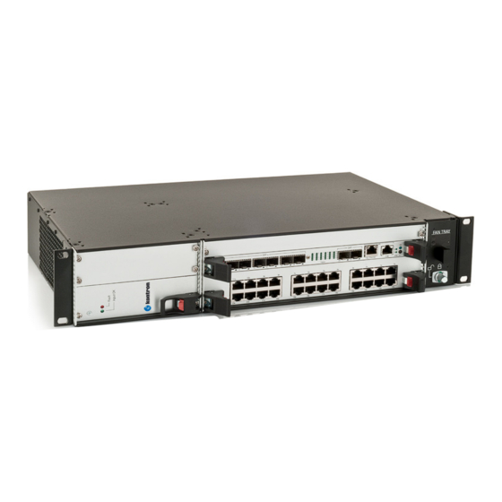
Introduction Product Overview The CP6930-RM is a standard 19 inch rack mountable switched, based on the CP6930 6U CompactPCI Ether- net Switch providing Layer 2 and Layer 3 switching/routing functions. It is available in two versions, either 12 (1U height) or 24 x 1000Base-T (2U height) ports to the front plus 8 x 1 Gigabit Ethernet front panel Interfaces via standard MSA SFP+ cages. - Page 18 • CPCI Keying: The backplane has an IO voltage of 3.3V and is populated with a Cadmium Yellow coding key in the P1 connector cavity 1.1.1.4 Front Interface Board • Two versions: • 1U with 12 ports 10/100/1000Base-T • 2U with 24 ports 10/100/1000Base-T CP6930-RM User Guide www.kontron.com...
-
Page 19: Hot Swap Capability
Please refer to the PICMG 2.1 R2.0 specification for additional details. In a 2U CP6930-RM-24 Ethernet Switch, two power supply slots are compliant to hot swap and power sharing, when using P47 power supplies from Kontron. -
Page 20: Temperature
• Peak Acceleration: 15 g, Shock Duration: 11 ms half sine, Shock Counts: 500/direction, Recovery Time: 1.2.8 Safety The system is designed to meet or meets the following requirements: • UL 60950-1, 3rd edition (US and Canada) • EN 60950-1 (Europe) • LVD 2006/95-EG CP6930-RM User Guide www.kontron.com... -
Page 21: Electromagnetic Compatibility
• Intelligent Platform Management Interface Specification V1.5 • IEEE 802.3, 2000 • IEEE 802.3ae 2002 • Small Form-factor Pluggable (SFP) Transceiver MultiSource Agreement (MSA), Sept. 14th, 2000 • IEC 60068-2-6, IEC 60068-2-27, IEC 60068-2-29 • EN 60950 CP6930-RM User Guide www.kontron.com... -
Page 22: Software Support
Introduction 1.4 Software Support The following table contains information related to software supported by the CP6930-RM. Table 1-1: CP6930-RM Software Specification CP6930-RM SPECIFICATIONS General • Reliable field upgrades for all software components • Dual boot images with roll-back capability •... - Page 23 Introduction Table 1-1: CP6930-RM Software Specification (Continued) CP6930-RM SPECIFICATIONS • DVMRP IP Multicast • PIM-DM • PIM-SM • IGMP (Internet Group Message Protocol) v2 and v3 • IGMP Proxy • Applications SNTP client for retrieving accurate time and date information •...
- Page 24 Chapter 2 Installation www.kontron.com...
-
Page 25: Installation
2.1 Safety Requirements The following safety precautions must be observed when installing or operating the CP6930-RM. Kontron assumes no responsibility for any damage resulting from failure to comply with these requirements. -
Page 26: Installation In A 19" Industrial Cabinet
• Ensure that the air inlet and outlet openings are kept clear and free from any obstructions. • Leave at least 10 cm (approx. 4 inch) of free space to the front and rear of the CP6930-RM when install- ing it from the 19'' industrial cabinet in order to avoid possible overheating and ease cable installa- tion. -
Page 27: Connecting The Power Cable And Power On
• Keep the air inlet and outlet clear. 2.3 Air Flow The CP6930-RM Ethernet switch requires a certain air flow to avoid overheating. Depending on the size of the housing, two different hot swap fan modules are installed. The following picture depicts the principal air flow:... -
Page 28: Replacing The System Fans
In case of a defective fan or to clean the fans, the hot swap fan modules can be removed from the housing. The fan module is changeable while the system is powered up. Note... Continuous operation of the CP6930-RM is permitted only with a functional fan module. Short (<1 minute) interruption of the air flow is allowed for mainte- nance purposes. -
Page 29: Replacing The System Power Supplies
Defective components may only be replaced by original Kontron spare parts. 2.5 Replacing the System Power Supplies The CP6930-RM is provided with a single Kontron 200W AC power supply, where the CP6930-RM-24 can be fit- ted with two redundant Kontron power supplies . -
Page 30: Replacing The Front Interfaces
4. The CP6930 is now ready for operation. Refer to the CP6930 User Guide for further instructions. 2.7 Replacing the Front Interfaces The CP6930-RM is provided with two different front interface modules: • CP6930-RM-12 provides 12 ports 10/100/1000Base-T • CP6930-RM-24 provides 24 ports 10/100/1000Base-T To replace these boards, the following procedure must be applied: 1. -
Page 31: Software Installation
The procedure for assigning an IP address to the serviceport is described in the following. User input is printed in bold letters. 1. Connect to serial port on the front plate (using the Kontron DB9 adapter cable) or RIO module (using a RJ45 straight cable). -
Page 32: In-Band Cli Access
4. Set IP address, netmask and default gateway. (see below for an example IP address setting). (Ethernet Fabric) #network parms 192.168.50.107 255.255.255.0 192.168.50.254 The GbE management interface is available from now on. Alternatively, DHCP can be set for the network port. CP6930-RM User Guide www.kontron.com... - Page 33 To access the CLI via Fast Ethernet port, open a telnet connection to the configured IP address, port 23. It might make sense to separate the management network from the data path by setting appropriate VLANs For additional information on the system configuration, refer to the CP6930 CLI Reference Manual. CP6930-RM User Guide www.kontron.com...
- Page 34 Chapter 3 Functional Description www.kontron.com...
-
Page 35: Functional Description
• Internal backplane • Front interface board, either 12 or 24 10/100/1000Base-T copper ports • Power supply, option for second redundant power supply inside the CP6930-RM-24 switch The following figure shows the block diagram of the Ethernet Switch CP6930-RM. Figure 3-1:... -
Page 36: Ethernet Infrastructure
• Broadcom StrataXGS®III Chip BCM56526 with 28 SGMII + 6 HiGig Port Gigabit Ethernet Layer-2/3 Switch Line rate switching for all packet sizes and conditions is supported on following interfaces: • 12 (CP6930-RM-12) or 24 (CP6930-RM-24) Link Ports to front interface module [10/100/1000Base-T via external Copper PHY] • 8 front panel uplinks: •... -
Page 37: Write Protection Feature
• The CP6930 Ethernet Switch front panel • The 12 port copper front panel of the CP6930-RM-12 • The 24 port copper front panel of the CP6930-RM-24 • Spare front panel of the CP6930-RM-24 for optional 6U CompactPCI System CPU CP6930-RM User Guide www.kontron.com... -
Page 38: Cp6930 Front Panel Ports
• 1x RS232 for Management (RJ45 connector) Table 3-1: SFP and SFP+ Connector Pin Number Signal Pin Number Signal VeeT VeeT Tx Fault Tx Disable VeeT VccT VccR MOD-ABS VeeR Rate Select 0 RX_LOS Rate Select 1 VeeR VeeR CP6930-RM User Guide www.kontron.com... - Page 39 Functional Description Table 3-2: Front RJ45 Ethernet Connector Contact BI_DA+ BI_DA- BI_DB+ BI_DC+ BI_DC- BI_DB- BI_DD+ BI_DD- Link/Activity Speed Table 3-3: Front RS232 Direction Signal CP6930-RM User Guide www.kontron.com...
-
Page 40: Cp6930 Front Panel Leds
The front panel provides 24 LEDS for status indication for the standard fabric interfaces. The LED color is green with the following states: • Off link down • On link up but no activity • Blinking link up and activity CP6930-RM User Guide www.kontron.com... -
Page 41: Cp6930 Front Panel Hotswap Switches
In a compactPCI system the hot swap signal can be used to notify the system controller for hot swap and redundant operation. This is not supported on the CP6930. For more information refer to the CP6930 User Manual CP6930-RM User Guide www.kontron.com... -
Page 42: Cp6930-Rm-12 Copper Front Interface
Functional Description 3.7.4 CP6930-RM-12 Copper Front Interface The CP6930-RM-12 supports 12 additional 10/100/1000Base-T interfaces as shown on the following picture: Figure 3-3: CP6930-RM-12 Copper Front Interface The port enumeration is as following: Table 3-7: CP6930-RM-12 Port Assignment CLI Port Reference... -
Page 43: Cp6930-Rm-24 Copper Front Interface
BI_DB- BI_DD+ BI_DD- Link/Activity Speed 3.7.5 CP6930-RM-24 Copper Front Interface The CP6930-RM-24 supports 24 additional 10/100/1000Base-T interfaces as shown on the following picture: Figure 3-4: CP6930-RM-24 Copper Front Interface The port enumeration is as following: Table 3-9: CP6930-RM-24 Port Assignment... -
Page 44: Cp6930-Rm-24 Spare Slot
Speed 3.7.6 CP6930-RM-24 Spare Slot The topmost slot of the CP6930-RM-24 is reserved for a CompactPCI system CPU. It is possible to route two PICMG2.16 compliant Ethernet ports of the CPU (J4) to the appropriate interfaces of the CP6930 switch board (CPU port a to 0/24 and CPU port b to 0/23). - Page 45 Chapter 4 Software Description www.kontron.com...
-
Page 46: Software Description
Entering "?" provides a list of possible built-in commands, "printenv" provides a list of current environment settings. The bootloader shell can be used to customize boot options and system startup by changing some of its environment variables. The list of available options can be found in the CP6930 User Guide. CP6930-RM User Guide www.kontron.com... -
Page 47: Ipmi Firmware
The memory subsystem of the PM consists of an integrated flash memory to hold the PM operation code and integrated RAM for data. Communication over IPMB (Backplane I²C bus) to the optional CompactPCI CPU in a CP6930-RM-24 switch ensures that 'post-mortem' logging information is available even if the main proces- sor becomes disabled. - Page 48 Appendix A Getting Help www.kontron.com...
-
Page 49: A Getting Help
Tel.: +49 (0) 8341 803 333 Fax: (450) 437-8053 Fax: +49 (0) 8341 803 339 If you have any questions about Kontron, our products, or services, visit our Web site at: www.kontron.com You also can contact us by E-mail at: North America: support@ca.kontron.com EMEA: support-kom@kontron.com... -
Page 50: When Returning A Unit
• E-mail • Send us an e-mail at: RMA@ca.kontron.com in North America or at: orderprocessing@kontron- modular.com in EMEA. In the e-mail, you must include your name, your company name, your ad- dress, your city, your postal/zip code, your phone number, and your e-mail. You must also include the serial number of the defective product and a description of the problem.
Need help?
Do you have a question about the CP6930-RM and is the answer not in the manual?
Questions and answers