
Related Manuals for Kontron CP6924


Summary of Contents for Kontron CP6924
- Page 1 User Guide CP6924-1-RA-A Document Revision 1.1 Date: November, 2015 www.kontron.com...
-
Page 2: Revision History
Disclaimer Copyright © 2015 Kontron AG. All rights reserved. All data is for information purposes only and not guaranteed for legal purposes. Infor- mation has been carefully checked and is believed to be accurate; however, no responsibility is assumed for inaccuracies. Kontron and the Kontron logo and all other trademarks or registered trademarks are the property of their respective owners and are recognized. -
Page 3: Table Of Contents
1.2.13 Lead-free ....................15 Software Support ....................16 Installation ....................... 18 Safety Requirements ..................18 CP6924 Initial Installation Procedures ..............19 Standard Removal Procedures ................20 Software Installation ..................20 Quick Start ....................... 21 2.5.1 Out-of-Band CLI Access .................. 21 2.5.2 In-Band CLI Access .................. - Page 4 4.2.4 Routing Package MIBs ................... 42 4.2.5 QoS Package MIBs ..................42 4.2.6 Multicast package MIBs .................. 42 4.2.7 Security MIBs ....................43 4.2.8 Kontron Private MIBs ..................43 Bootloader ...................... 44 4.3.1 Power On Self Test ..................45 4.3.2 Bootloader Shell Options ................46 4.3.3 Bootloader Pushbutton Reset ................
- Page 5 CP6924-1-RA-A User Guide Thermal Considerations ....................69 Power Considerations ....................71 Baseboard ....................... 71 Backplanes ...................... 71 www.kontron.com...
- Page 6 CP6924-1-RA-A User Guide List of Tables Table 1-1: CP6924 Software Specification................16 Table 3-1: Ethernet Port Mapping ..................25 Table 3-2: Peripheral Manager AD Input and Voltage Assignment........... 27 Table 3-3: Front RJ45 Ethernet Connector ................. 28 Table 3-4: Connector J1 Pinout ..................29 Table 3-5: Connector J2 Pinout ..................
- Page 7 CP6924-1-RA-A User Guide List of Figures Figure 3-1: CP6924-1-RA-A Functional Block Diagram ............24 Figure 5-1: Position of Temperature Sensors, Top Side View ............ 69 www.kontron.com...
-
Page 8: Proprietary Note
This document contains information proprietary to Kontron. It may not be copied or transmitted by any means, disclosed to others, or stored in any retrieval system or media without the prior written consent of Kontron AG or one of its authorized agents. -
Page 9: Safety Instructions
It was also designed for a long fault-free life. However, the life expectancy of your product can be drastically reduced by improper treatment during unpacking and installation. Therefore, in the interest of your own safety and of the correct operation of your new Kontron product, you are requested to conform with the following guidelines. - Page 10 CP6924-1-RA-A User Guide Laser Lights Laser light from fiber-optic transmission cables and components can damage your eyes. The laser components plugged into the switch are Class 1 laser components. Class 1 laser is considered incapable of pro- ducing damaging radiation levels during normal operation or mainte- nance.
-
Page 11: General Instructions On Usage
TWO YEAR LIMITED HARDWARE WARRANTY ing. However, no other warranties that may be granted or implied by anyone on behalf of Kontron are valid unless the con- sumer has the express written consent of Kontron. -
Page 12: Introduction
CP6924-1-RA-A User Guide Introduction Product Overview 1.1.1 CP6924 Features The board is composed of the following building blocks: • Ethernet Infrastructure • Unit Computer and Memory • IPMI • Power Supply 1.1.1.1 Ethernet Infrastructure • Broadcom StrataXGS®IV Metro Ethernet Access Switch Architecture •... -
Page 13: General Compliances
CP6924-1-RA-A User Guide 1.1.1.3 IPMI • NXP LPC2368 32-Bit Microcontroller • PICMG 2.9 / IPMI 1.5 compliant • Dual Image Support • 2 MByte Flash (Boot Image) • 64 kByte EEPROM (FRU) • Board Voltage and current monitoring • Board Temperature monitoring via I²C enabled sensors •... -
Page 14: Technical Specification
10 cycles/axis, 3 directions [x, y, z] Note... If the CP6924-1-RA-A board is used in heavy shock and vibration environment, the hole system must withstand these requirements. This means the chassis, backplane and guid- erails should be designed for harsh environment. Guide rails with wedge locks are recom- mend. -
Page 15: Safety
CP6924-1-RA-A User Guide 1.2.8 Safety The boards are designed to meet or meets the following requirements: • UL 60950-1, 2nd Edition (US and Canada) • EN 60950-1, (Europe) The boards are designed to meet the following flammability requirement (as specified in Telcordia GR-63-CORE): •... -
Page 16: Software Support
CP6924-1-RA-A User Guide Software Support The following table contains information related to software supported by the CP6924. Table 1-1: CP6924 Software Specification CP6924 SPECIFICATIONS • General Reliable field upgrades for all software components • Dual boot images with roll-back capability •... - Page 17 • Support for retrieving and installing multiple configurations • Support for startup configurations based on the cPCI SGA/GA (Shelf Geograph- ical Address/Geographical Address), see CP6924 CLI Reference Manual, chap- ter „AutoInstall Commands“ • Supported MIBS For a list of supported MIBs, see chapter “Supported MIBs” on page 40 •...
-
Page 18: Installation
Safety Requirements The following safety precautions must be observed when installing or operating the CP6924. Kontron assumes no responsi- bility for any damage resulting from failure to comply with these requirements. WARNING Due care should be exercised when handling the board due to the fact that the heat sink can get very hot. -
Page 19: Cp6924 Initial Installation Procedures
CP6924-1-RA-A User Guide CP6924 Initial Installation Procedures The following procedures are applicable only for the initial installation of the CP6924 in a system. Procedures for standard removal and hot swap operations are found in their respective chapters. To perform an initial installation of the CP6924 in a system proceed as follows: 1. -
Page 20: Standard Removal Procedures
4. For removing the board from the system, refer to the system manual. Software Installation The CP6924 comes as a pre-installed system with all necessary OS, filesystem, drivers and applications factory-installed with default configurations. Updating the Software with new operating system or applications or new versions is provided by a dedicated update mech- anism, which is described in Chapter 4. -
Page 21: Quick Start
Gigabit Ethernet Serviceport The Gigabit Ethernet serviceport on the CP6924 front plate has no IP address set by default, it is necessary to assign an IP address statically or enable dhcp on the serviceport. Because the required configuration steps are done in the CLI, an initial access using the serial port is required. -
Page 22: In-Band Cli Access
In-Band CLI Access The GbE switch network port (in-band management access) on the CP6924 has no IP address set by default, it is necessary to assign an IP address either statically or by using DHCP to the network port. Because the required configuration steps are done in the CLI, an initial access using the serial port is required. - Page 23 To access the CLI via Gigabit Ethernet networkport, open a telnet connection to the configured IP address, port 23. It might make sense to separate the management network from the data path by setting appropriate VLANs For additional information on the system configuration, refer to the CP6924 CLI Reference Manual. www.kontron.com...
-
Page 24: Functional Description
CP6924-1-RA-A User Guide Functional Description This chapter describes the board specific items of the CP6924-1-RA-A. The base board is a standard Fabric 6U CompactPCI Gigabit Ethernet Switch with 24 channels. Figure 3-1: CP6924-1-RA-A Functional Block Diagram www.kontron.com... -
Page 25: Ethernet Infrastructure
CP6924-1-RA-A User Guide The board is composed of the following building blocks: • Ethernet Infrastructure • Unit Computer and Memory • IPMI • Power Supply Ethernet Infrastructure The fabric switch infrastructure is composed of • Broadcom StrataXGS®IV Chip BCM56334 with 24x 1GbE Ports (SGMII) and 4x 10GbE (XAUI) •... -
Page 26: Unit Computer And Memory
RTC Clock IPMI The CP6924 board supports an intelligent hardware management system, based on the Intelligent Platform Management Interface Specification 1.5. The hardware management system provides the ability to manage the power, cooling and inter- connect needs of intelligent devices, to monitor events and to log events to a central repository intelligent FRU (Field Replaceable Unit). -
Page 27: Voltage Sensors
CompactPCI IPMB-O interface 3.3.1 Voltage Sensors The Peripheral Manager has 6 AD converters. Two analog multiplexer are used to measure all voltages on the CP6924. The following table shows the settings of the multiplexer control signals. Table 3-2: Peripheral Manager AD Input and Voltage Assignment... -
Page 28: Board Interfaces
V(I/O). The CP6924 is compatible with all standard 6U CompactPCI passive backplanes with rear I/O support on the system slot. For accessing the GbE interfaces signals on connectors J3, J4 and J5 with a rear I/O module, a backplane with I/O support is necessary. -
Page 29: Table 3-4: Connector J1 Pinout
CP6924-1-RA-A User Guide 3.4.2.1 J1 Connector • Power +3.3V, +5.0V, V(I/O) • IPMB Power (+5.0V) • IPMB 0 • Hot Swap Table 3-4: Connector J1 Pinout Row A Row B Row C Row D Row E Row F V_5V_CPCI V_3V3_CPCI... -
Page 30: Table 3-5: Connector J2 Pinout
CP6924-1-RA-A User Guide 3.4.2.2 J2 Connector • Geographical Address • IPMB 1 • ALERT# Table 3-5: Connector J2 Pinout Row A Row B Row C Row D Row E Row F CPCI_GA[4] CPCI_GA[3] CPCI_GA[2] CPCI_GA[1] CPCI_GA[0] IPMB1_SDA IPMB1_SCL IPMB_ALERT# www.kontron.com... -
Page 31: Table 3-6: Connector J3 Pinout
CP6924-1-RA-A User Guide 3.4.2.3 J3 Connector • Link Port 1 to Link Port 8 (10/100/1000Base-T) • Link Port f • Shelf Geographical Address Table 3-6: Connector J3 Pinout Row A Row B Row C Row D Row E Row F... -
Page 32: Table 3-7: Connector J4 Pinout
V_5V_HS_RTM_F The J4 connector provides the rear RS232 interface and the Firmware Write Protect Disable signal. The CP6924 distributes a 5V power supply rail to the RTM via J4. A 4A fuse protects the board from overcurrent or short circuit. -
Page 33: Write Protection Feature
FL_DD9- Write Protection Feature The CP6924 supports hardware driven write protection for all non-volatile memory devices. Depending on the device, the protection is implemented either by a dedicated write protection signal, by disabling the write enable signal, or by the whole interface. -
Page 34: Software Description
This manual describes bootloader, Linux rootfs/kernel and IPMI firmware, last chapter introduces the update procedures. For additional information of system configuration using CLI commands refer to documentation “CP6924-1-RA-A CLI Refer- ence Manual”. -
Page 35: Fastpath Switching
CP6924-1-RA-A User Guide • RFC 3415 — View-based Access Control Model • RFC 3416 — Version 2 of SNMP Protocol Operations • RFC 3417 — Transport Mappings • RFC 3418 — Management Information Base (MIB) for the Simple Network Management Protocol (SNMP) •... - Page 36 CP6924-1-RA-A User Guide • IEEE 802.3ab — 1000Base-T • IEEE 802.3ac — VLAN tagging • IEEE 802.3ad — Link aggregation • IEEE 802.3ae — 10GbE • IEEE 802.3x — Flow control • ANSI/TIA-1057 — LLDP-MED • GARP — Generic Attribute Registration Protocol: clause 12, 802.1D-2004 •...
-
Page 37: Fastpath Routing
CP6924-1-RA-A User Guide • RFC 791 — IP • RFC 792 — ICMP • RFC 793 — TCP • RFC 826 — Ethernet ARP • RFC 894 — Transmission of IP Datagrams over Ethernet Networks • RFC 896 — Congestion Control in IP/TCP Networks •... -
Page 38: Fastpath Ipv6 Routing
CP6924-1-RA-A User Guide • RFC 3046 — DHCP/BOOTP relay • RFC 3101 — The OSPF “Not So Stubby Area” (NSSA) option • RFC 3107 — Carrying label information in BGP-4 • RFC 3137 — OSPF Stub Router Advertisement • RFC 3623 — Graceful OSPF Restart •... -
Page 39: Fastpath Quality Of Service
CP6924-1-RA-A User Guide 4.1.5 FASTPATH Quality of Service DiffServ • RFC 2474 — Definition of the differentiated services field (DS Field) in the IPv4 and IPv6 headers • RFC 2475 — An architecture for differentiated services • RFC 2597 — Assured forwarding PHB group •... -
Page 40: Fastpath Multicast
CP6924-1-RA-A User Guide 4.1.6 FASTPATH Multicast Core Features • RFC 1112 — Host extensions for IP multicasting • RFC 2236 — IGMP v2 • RFC 2365 — Administratively scoped boundaries • RFC 2710 — MLDv1 • RFC 3376 — IGMPv3 •... -
Page 41: Switching Package Mibs
CP6924-1-RA-A User Guide • RFC 3417 - SNMPV2-TM • RFC 3415 - View-based Access Control Model for SNMP MIB • RFC 3411 - SNMP-FRAMEWORK-MIB • RFC 3412 - SNMP-MPD-MIB • RFC 3413 - SNMP-NOTIFICATION-MIB • RFC 3413 - SNMP-PROXY-MIB (initial revision published as RFC 2273) •... -
Page 42: Routing Package Mibs
CP6924-1-RA-A User Guide • RFC 3291 — Textual Conventions for Internet Network Addresses • RFC 3635 — Etherlike MIB • RFC 3636 — IEEE 802.3 Medium Attachment Units (MAUs) MIB • RFC 4022 — Management Information Base for the Transmission Control Protocol (TCP) •... -
Page 43: Security Mibs
Ethernet features • Geographical Address • extended management features Kontron specific MIBs start with a “kex_”. Here‘s a list of MIBs provided (in this example for release GA 2.0) including its content: • kex_config • Set BSP startup services •... -
Page 44: Bootloader
SNMP can also be used for updating System Software, IPMI FW and PLD. Bootloader On the CP6924-1-RA-A Ethernet Switch, the bootloader 'u-boot' (universal bootloader) is used. The bootloader initializes the main components of the system like Unit Computer, DDR2 RAM, serial lines etc. for operation and performs a power on self test (POST). -
Page 45: Power On Self Test
CP6924-1-RA-A User Guide 4.3.1 Power On Self Test 4.3.1.1 Test Routines Upon power on or system reset, the bootloader performs the following power on self tests (POST): Table 4-1: POST tests Test Description Serial Onboard Unit Computer serial controller loopback test... -
Page 46: Bootloader Shell Options
CP6924-1-RA-A User Guide 4.3.2 Bootloader Shell Options The boot process can be interrupted by entering the bootstopkey phrase “stop”. This will open a bootloader shell session. Entering “?” provides a list of possible built-in commands, “printenv” provides a list of current environment settings. The bootloader shell can be used to customize boot options and system startup by changing some of its environment variables. - Page 47 CP6924-1-RA-A User Guide Table 4-3: Bootloader Environment Variables (Continued) Name Type Description contains the default base MAC address of the board which is read from VPD area. If ethaddr environment variable is changed and stored ethaddr Auto using 'saveenv', this value will override VPD setting af ter board restart.
-
Page 48: Bootloader Pushbutton Reset
4.3.3 Bootloader Pushbutton Reset When the pushbutton is pressed, the CP6924-1-RA-A glue logic performs a SysReset to the CPU. After reset has been issued, the board will restart with boot source 'Pushbutton' displayed on the serial console. If the pushbutton has been pressed for more than 3s, bootloader will detect this and drop into the boot firmware shell immediately. -
Page 49: Ipmi Firmware
CP6924-1-RA-A User Guide IPMI Firmware The Switch Management Controller communicates with the onboard Module Management Controller (MMC) using the Key- board Controller Style (KCS) interface. The bootloader is able to communicate with the MMC, e.g. for POST error logging purposes and fault resilient purposes. -
Page 50: Table 4-5: Hpm.1 Commands
CP6924-1-RA-A User Guide Table 4-4: Standard Commands (Continued) IPMI 2.0 Spec. Support on Command NetFn section CP6924-1-RA-A Chassis Commands Chassis Control 28.3 Chassis O / Yes Event Commands Set Event Receiver 29.1 M / Yes Get Event Receiver 29.2 M / Yes Platform Event (a.k.a. -
Page 51: Table 4-6: Kontron Oem Commands
HPM.1 Get Upgrade Status HPM.1 Activate Firmware HPM.1 Query Self-Test Results HPM.1 Query Rollback Status HPM.1 Initiate Manual Rollback HPM.1 4.4.1.2 Kontron OEM Commands And Extensions Table 4-6: Kontron OEM Commands Command NetFn Code OemApSetControlState OemApGetControlState OemApGetFirmwareSysUpTime OemApFormatStorage OemApSetSdrLocatorString OemApSetSerialNumber... - Page 52 Byte Data Field Request Data Completion Code Device ID 10h = Kontron IPMC based on NXP Microcontroller Device Revision [7] - 1b = device provides Device SDRs [6-0] – 0000000b = Reserved Firmware Revision [7] – 0b = normal operation [6:0] –...
- Page 53 CP6924-1-RA-A User Guide Example: # ipmitool bmc info Device ID : 16 Device Revision Firmware Revision : 0.90 IPMI Version : 1.5 Manufacturer ID : 15000 Manufacturer Name : Kontron Product ID : 1704 (0x06a8) Product Name : Unknown (0x6A8)
- Page 54 CP6924-1-RA-A User Guide OemApSetNvData / OemApGetNvData Command These commands provide raw access to the internally held parameter database that is stored inside the I2C EEPROM attached to the IPMI controller. NetFn oemApSetNvData OEM = 3Eh Byte Data Field Pass Code 0: ~’K’...
-
Page 55: Board Sensors
CP6924-1-RA-A User Guide OemApLoadNvDefaults Command This command is used to re-initialize the parameter database to its default values. NetFn oemApLoadNvDefaults OEM = 3Eh Byte Data Field Pass Code 0: ~’K’ Pass Code 1: ~’o’ Request data Pass Code 2: ~’n’... -
Page 56: Table 4-7: Sensor List
CP6924-1-RA-A User Guide For OEM (Kontron) specific sensor types and reading types in the following table please refer to the next chapter. Table 4-7: Sensor List Sensor Sensor ID Sensor Type Code Description Record ID CP6924 FRU Device Locator Record... - Page 57 CP6924-1-RA-A User Guide Example # ipmitool sdr list S02:T_PCB | 32 degrees C | ok S02:T_PHY1 | 53 degrees C | ok S02:T_PHY2 | 64 degrees C | ok S02:T_PHY3 | 44 degrees C | ok S02:V_0V9_VTT | 0.90 Volts...
-
Page 58: Table 4-8: Ipmb Link (Type C3H) Reading
CP6924-1-RA-A User Guide 4.4.2.2 OEM Sensors OEM IPMB Link (Type C3h) Table 4-8: IPMB Link (Type C3h) Reading Offset Request data Sensor Number Completion Code Sensor Reading [7:4] – Reserved, ignore on read [3] – IPMB-L Override State 0b = override state, bus isolated 1b = local control state, MMC determines state of the bus [2:0] –... -
Page 59: Table 4-9: Ipmb Link (Type C3H) Event Message
CP6924-1-RA-A User Guide Table 4-9: IPMB Link (Type C3h) Event Message Offset Event Message Rev Sensor Type F2h – Module Hot Swap Sensor Number [7] – Event Direction 1b = Deassertion 0b = Assertion [6-0] – Event Type 6Fh = Generic Availability Event Data 1 [7:4] –... -
Page 60: Table 4-10: Mmc Reboot (Type 24H) Reading
CP6924-1-RA-A User Guide MMC Reboot (Type 24h) Table 4-10: MMC Reboot (Type 24h) Reading Offset Request data Sensor Number Completion Code Sensor Reading 00h – ignore on read Standard IPMI Byte. (See “Get Sensor Reading in the IPMI Specification) Response data [7:2] –... -
Page 61: Table 4-12: Mmc Fwup (Type C7H) Reading
CP6924-1-RA-A User Guide MMC FwUp (Type C7h) Table 4-12: MMC FwUp (Type C7h) Reading Offset Request data Sensor Number Completion Code Sensor Reading 00h = first boot after upgrade 01h = first boot after rollback Response data All other values are reserved. -
Page 62: Table 4-14: Post Fail (Type 0Fh) Reading
CP6924-1-RA-A User Guide POST Fail (Type 0Fh) Table 4-14: POST Fail (Type 0Fh) Reading Offset Request data Sensor Number Completion Code Sensor Reading 00h – ignore on read Response data Standard IPMI Byte. (See “Get Sensor Reading in the IPMI Specification) [7:1] –... -
Page 63: Table 4-16: Boot Fail (Sensor Type 1Eh) Reading
CP6924-1-RA-A User Guide Boot Fail *(Sensor Type 1Eh) Table 4-16: Boot Fail (Sensor Type 1Eh) Reading Offset Request data Sensor Number Completion Code Sensor Reading 00h – ignore on read Standard IPMI Byte. (See “Get Sensor Reading in the IPMI Specification) [7:4] –... -
Page 64: Table 4-18: Temperature Sensor Thresholds [°C]
CP6924-1-RA-A User Guide * Standard sensor type from IPMI2.0 defined for x86 systems. 4.4.2.3 Sensor Thresholds Following tables show sensor thresholds for temperature, voltage and current sensors. Table 4-18: Temperature Sensor Thresholds [°C] SENSOR Number/ ID Lower criti- Lower non... -
Page 65: Board Fru Information
Supported are the following FRU data areas and data fields (shown values are examples, which may differ, depending on the used board typ): FRU Board Info Area • Manufacturing date / time • Board manufacturer: “KONTRON ” • Board Product Name: “ S1704” • Board Serial Number : “0123456789” *) • Board Part Number: “1055-1103”... -
Page 66: Software Administration
CP6924-1-RA-A User Guide Software Administration A running CP6924-1-RA-A system requires – after the bootloader has passed control to the kernel – the kernel itself, the root file system (initrd), the FASTPATH switching application and the IPMI firmware. The system supports an on-board integrated 1x128 MB NOR flash that is also used as the power-up boot source. It contains the bootloader as well as the operating system and the application data. -
Page 67: Updating System Software
The system update package (CP6924-system-l2onlyres-<release>.pkg) contains an image of bootloader, kernel, root filesystem as well as a MD5 checksum file for consistency check. When performing an update, the software package is loaded from a remote TFTP server. A software update of the CP6924 is done by performing the following steps: Copy the required file onto your tftp server. -
Page 68: Updating Ipmi Firmware
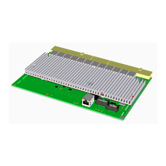
The IPMI firmware package file is provided in .pkg format and is stored in the data/update directory of the release directory tree. (Ethernet Fabric) #copy tftp://192.168.50.5/CP6924-ipmi-GA-2.00.pkg ipmi Flashing a new IPMI firmware will disable the IPMI Controller for some minutes. - Page 69 Peripheral Manager. Although temperature sensing information is made available to the PM, the CP6924 itself does not provide any active means of temperature regulation. As long as the temperature values stay below their upper critical threshold, all components on the CP6924 are considered to be operated within their specified temperature range.
- Page 70 CP6924-1-RA-A User Guide When developing applications using the CP6924, the system integrator must be aware of the overall system thermal requirements. A system chassis must be provided which satisfy these requirements. Measurements proofed that with forced air cooling of > 1.5 m/s, operation is possible under ambient temperature of +85°C and maximum load on all interfaces while all temperatures of on-board components stay below their critical thresholds.
-
Page 71: Table 6-1: Maximum Input Power Voltage Limits
Baseboard The CP6924 has been designed for optimal power input and distribution. Still it is necessary to observe certain criteria essential for application stability and reliability. The board is supplied by 3.3V and 5.0V from the backplane. All supply volt- ages from the backplane are enabled with a predefined ramp-up time. - Page 72 CP6924-1-RA-A User Guide CORPORATE OFFICES Europe, Middle East & Africa North America Asia Pacific Lise-Meitner-Straße 3-5 14118 Stowe Drive 17 Building,Block #1, ABP. 86156 Augsburg Poway, CA 92064-7147 188 Southern West 4th Ring Road Germany Beijing 100070, P.R.China Tel.: + 49 (0) 821 / 4086 01 Tel.: + 1 888 294 4558...
Need help?
Do you have a question about the CP6924 and is the answer not in the manual?
Questions and answers