
Subscribe to Our Youtube Channel
Related Manuals for Kontron CP6940


Summary of Contents for Kontron CP6940
-
Page 1: User Guide
User Guide CP6940 Document Revision 0.9 (Draft Version) Date: September 2019 www.kontron.com... -
Page 2: Disclaimer
Kontron would like to point out that the information contained in this manual may be subject to alteration, particularly as a result of the constant upgrading of Kontron products. This document does not entail any guarantee on the part of Kon- tron with respect to technical processes described in the manual or any product characteristics set out in the manual. -
Page 3: Revision History
IRONMENTAL DAMAGE (COLLECTIVELY, "HIGH RISK APPLICATIONS"). You understand and agree that your use of Kontron devices as a component in High Risk Applications is entirely at your risk. To minimize the risks associated with your products and applications, you should provide adequate design and ope- rating safeguards. -
Page 4: Customer Comments
If you have any difficulties using this guide, discover an error, or just want to provide some feedback, please send a mes- sage to Kontron. Detail any errors you find. We will correct the errors or problems as soon as possible and post the revi- sed user guide on our website. -
Page 5: Symbols
CP6940 User Guide Symbols The following symbols may be used in this manual. DANGER indicates a hazardous situation which, if not avoided, will result in death or serious injury. WARNING indicates a hazardous situation which, if not avoided, could result in death or serious injury. -
Page 6: For Your Safety
Therefore, in the inte- rest of your own safety and of the correct operation of your new Kontron product, you are requested to conform with the following guidelines. -
Page 7: General Instructions On Usage
General Instructions on Usage In order to maintain Kontron’s product warranty, this product must not be altered or modified in any way. Changes or modifications to the product, that are not explicitly approved by Kontron and described in this User Guide or received from Kontron’s Technical Support as a special handling instruction, will void your warranty. -
Page 8: Table Of Contents
1.2.12 WEEE ..................................... 15 1.2.13 RoHS Compliance ................................15 1.2.14 Lead-free ..................................... 15 Software Support ................................16 2/ CP6940 Installation ..........................18 Safety Requirements ..............................18 CP6940 Initial Installation Procedures .........................19 Standard Removal Procedures ..........................20 Software Installation ..............................21 Quick Start ..................................21 2.5.1 Out-of-Band CLI Access .............................. - Page 9 CP6940 User Guide 3.3.2 Current sensors ................................28 Board Interfaces ................................29 3.4.1 Front Panel Elements ..............................29 3.4.2 Front Panel Switches ..............................31 3.4.3 Front Panel Ports ................................32 3.4.4 Front Panel Management Port RJ45 .........................33 3.4.5 CompactPCI Connectors ............................... 34 Write Protection Feature ............................
- Page 10 List of Tables Table 1: CP6940 Software Specification ..........................16 Table 2: Ethernet Port Mapping............................26 Table 3: CP6940 Voltages and Operational ranges......................28 Table 4: SFP Uplink Port Pinout ............................32 Table 5: Front RJ45 Ethernet Connector........................... 33 Table 6: Front RS232 ................................33 Table 7: Serial console terminal cable interface: RJ45 Female to DB9 Female ..........34...
- Page 11 CP6940 User Guide Figure 1: CP6940-RA-OC Functional Block Diagram ....................24 Figure 2: CP6940-SA-OC(-V) Functional Block Diagram ..................25 Figure 3: Front Panel of the CP6940-RA-OC-P......................29 Figure 4: Front Panel of the CP6940-RA-OC .........................29 Figure 5: Font Panel of the CP6940-SA-OC-V.......................29 Figure 6: LED description CP6940-RA-OC-P .........................30...
-
Page 12: 1/ Introduction
Introduction This manual describes the features of the CP6940 board. The use of this User Guide implies a basic knowledge of PC hard- and software. This manual is focused on describing the special features and is not intended to be a standard PC textbook. -
Page 13: General Compliances
CP6940 User Guide 1.1.1.2 Unit Computer and System Memory • NXP Layerscape LS1020 CPU running at 1200 MHz • Used for switch provisioning and diagnostics • 2 GBytes DDR3 RAM • 4 GBytes eMMC (pSLC) • 4 MBytes SPI FLASH Memory •... -
Page 14: Technical Specification
100 Hz to 1000 Hz PSD = 0.04 g2/Hz • 1000 Hz to 2000 Hz PSD decreasing at 6 dB/octave The CP6940-RA-OC and CP6940-RA-OC-P boards are designed to meet the requirements according ANSI VITA47 V2: • withstand vibration for 1 hour per axis: •... -
Page 15: Shock
CP6940 User Guide If the CP6940 board is used in heavy shock and vibration environment, the hole system must withstand these requirements. This means the chassis, backplane and guiderails should be designed for harsh environment. Guide rails with wedge locks are recommend. -
Page 16: Software Support
CP6940 User Guide Software Support The following table contains information related to software supported by the CP6940 Table 1: CP6940 Software Specification CP6940 SPECIFICATIONS • General Reliable field upgrades for all software components • Dual boot images with roll-back capability •... - Page 17 • Support for retrieving and installing multiple configurations • Support for startup configurations based on the cPCI SGA/GA (Shelf Geo- graphical Address/Geographical Address), see CP6940 CLI Reference Man- ual, chapter „AutoInstall Commands“ • Supported MIBS For a list of supported MIBs, see chapter “Supported MIBs” on page 41 •...
-
Page 18: 2/ Cp6940 Installation
Safety Requirements The following safety precautions must be observed when installing or operating the CP6940. Kontron assumes no responsibility for any damage resulting from failure to comply with these requirements. Due care should be exercised when handling the board due to the fact that the heat sink can get very hot. -
Page 19: Cp6940 Initial Installation Procedures
CP6940 User Guide CP6940 Initial Installation Procedures The following procedures are applicable only for the initial installation of the CP6940 in a system. Procedures for stan- dard removal and hot swap operations are found in their respective chapters. To perform an initial installation of the CP6940 in a system proceed as follows: Ensure that the safety requirements indicated in chapter Safety Requirements are observed. -
Page 20: Standard Removal Procedures
Ensure that the safety requirements indicated in chapter Safety Requirements are observed. Care must be taken when applying the procedures below to ensure that neither the CP6940 nor other system boards are physically damaged by the application of these procedures. -
Page 21: Software Installation
Gigabit Ethernet Serviceport The Gigabit Ethernet serviceport on the CP6940 front plate has no IP address set by default, it is necessary to assign an IP address statically or enable dhcp on the serviceport. Because the required configuration steps are done in the CLI, an ini- tial access using the serial port is required. -
Page 22: In-Band Cli Access
In-Band CLI Access The GbE switch network port (in-band management access) on the CP6940 has no IP address set by default, it is neces- sary to assign an IP address either statically or by using DHCP to the network port. Because the required configuration steps are done in the CLI, an initial access using the serial port is required. - Page 23 To access the CLI via Gigabit Ethernet networkport, open a telnet connection to the configured IP address, port 23. It might make sense to separate the management network from the data path by setting appropriate VLANs For additional information on the system configuration, refer to the CP6940 CLI Reference Manual. www.kontron.com...
-
Page 24: 3/ Functional Description
CP6940 User Guide Functional Description This chapter describes the board specific items of the CP6940. The base board is a standard Fabric 6U CompactPCI Giga- bit Ethernet Switch with 24 channels. CP6940 RA-OC SGMII Quad SGMII 4P0 10/100/1000 4x MDI... -
Page 25: Figure 2: Cp6940-Sa-Oc(-V) Functional Block Diagram
Hotswap TMP423 AT24C512 25DF161 1.0 V_CPU 1.0 V_SW IMON 5V/3.3V 1.0 V_Phy Figure 2: CP6940-SA-OC(-V) Functional Block Diagram The board is composed of the following building blocks: • Ethernet Infrastructure • Unit Computer and Memory • IPMI • Power Supply www.kontron.com... -
Page 26: Ethernet Infrastructure
CP6940 User Guide Ethernet Infrastructure The fabric switch infrastructure includes: • Broadcom high port count integrated switch with 100-FX/1G/2.5G/5G/10G-Capable SerDes lanes • BCM56174 with 28x 1GbE Ports (SGMII) and 12x 10GbE • Unit Computer manages Switch via PCIe Gen2 x1 (5Gbps) •... -
Page 27: Unit Computer And Memory
RTC Clock IPMI The CP6940 board supports an intelligent hardware management system, based on the Intelligent Platform Manage- ment Interface Specification 1.5. The hardware management system provides the ability to manage the power, cooling and interconnect needs of intelligent devices, to monitor events and to log events to a central repository intelligent FRU (Field Replaceable Unit). -
Page 28: Voltage Sensors
• CompactPCI IPMB-O interface 3.3.1 Voltage Sensors The Peripheral Manager measure all voltages on the CP6940. The following table shows the all voltages used on the CP6940 and their recommended operating range. Table 3: CP6940 Voltages and Operational ranges Nominal Voltage... -
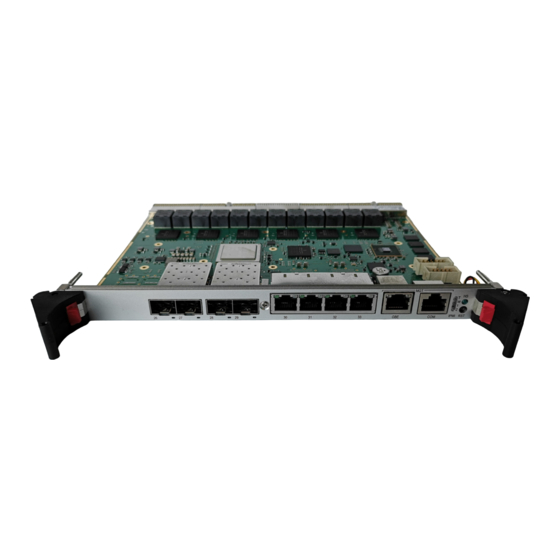
Page 29: Board Interfaces
-SA-OC-V At the CP6940-SA-OC-V faceplate are the two SFP+ cages, two SFP cages, the four front RJ45 ports, the front RS232 and the management port accessible. Also are there the status LEDs for the 28 GBE ports, the hot swap LED the LED1 and the LED2 visible. -
Page 30: Figure 6: Led Description Cp6940-Ra-Oc-P
CP6940 User Guide 3.4.1.4 CP6940 Front Panel LEDs Figure 6: LED description CP6940-RA-OC-P Figure 7: LED description CP6940-RA-OC/CP6940-SA-OC-V 3.4.1.5 Hot Swap LED (Blue LED) • payload activated • ready for hot swap • Blinking not specified yet 3.4.1.6 LED1 Alarm (red) •... -
Page 31: Front Panel Switches
CP6940 User Guide 3.4.1.10 QSFP LEDs • link down • link up but no activity • Blinking link up and activity 3.4.1.11 Front RJ45 status LEDs Link/Activity: Green LED • link down • link up but no activity • Blinking... -
Page 32: Front Panel Ports
CP6940 User Guide 3.4.3 Front Panel Ports 3.4.3.1 SFP/SFP+ Uplink Ports The SFPs uplink ports are according the Small Form-factor Pluggable (SFP) Transceiver MultiSource Agreement (MSA), Sept. 14th, 2000. The SFP connectors have the following pin assignment: Table 4: SFP Uplink Port Pinout... -
Page 33: Front Panel Management Port Rj45
CP6940 User Guide 3.4.4 Front Panel Management Port RJ45 The standard RJ45 has the following Pin Assignment. Table 5: Front RJ45 Ethernet Connector Contact Contact Contact Contact 30.1 BI_DA+ 31.1 BI_DA+ 32.1 BI_DA+ 33.1 BI_DA+ 30.2 BI_DA– 31.2 BI_DA– 32.2 BI_DA–... -
Page 34: Compactpci Connectors
V(I/O). The CP6940 is compatible with all standard 6U CompactPCI passive backplanes with rear I/O support on the system slot. For accessing the GbE interfaces signals on connectors J3, J4 and J5 with a rear I/O module, a backplane with I/O support is necessary. -
Page 35: Table 8: Connector J1 Pinout
CP6940 User Guide 3.4.5.1 J1 Connector • Power +3.3V, +5.0V, V(I/O) • IPMB Power (+5.0V) • IPMB 0 • Hot Swap Table 8: Connector J1 Pinout Pin Row A Row B Row C Row D Row E Row F V_5V_CPCI... -
Page 36: Table 9: Connector J2 Pinout
CP6940 User Guide 3.4.5.2 J2 Connector • Geographical Address • IPMB 1 • ALERT# Table 9: Connector J2 Pinout Row A Row B Row C Row D Row E Row F CPCI_GA[4] CPCI_GA[3] CPCI_GA[2] CPCI_GA[1] CPCI_GA[0] IPMB1_SDA IPMB1_SCL IPMB_ALERT# www.kontron.com... -
Page 37: Table 10: Connector J3 Pinout
CP6940 User Guide 3.4.5.3 J3 Connector • Link Port 1 to Link Port 8 (10/100/1000Base-T) • Link Port f • Shelf Geographical Address Table 10: Connector J3 Pinout Row A Row B Row C Row D Row E Row F... -
Page 38: Table 11: Connector J4 Pinout
V_5V_HS_RT- The J4 connector provides the rear RS232 interface and the Firmware Write Protect Disable signal. The CP6940 distrib- utes a 5V power supply rail to the RTM via J4. A 4A fuse protects the board from overcurrent or short circuit. -
Page 39: Write Protection Feature
FL_DC9+ FL_DC9- FL_DB9+ FL_DB9- FL_DD9+ FL_DD9- Write Protection Feature TThe CP6940 supports hardware driven write protection for all non-volatile memory devices. The protection is imple- mented by disabling the write enable signal, for all non-volatile memory devices. www.kontron.com // 39... -
Page 40: 4/ Software Description
This manual describes bootloader, Linux rootfs/kernel and IPMI firmware, last chapter introduces the update procedures. For additional information of system configuration using CLI commands refer to documentation “CP6940 CLI Reference Manual”. -
Page 41: Fastpath Switching
CP6940 User Guide • RFC 3268—AES cipher suites for Transport layer security • SSH 1.5 and 2.0 • RFC 4252—SSH authentication protocol • RFC 4253—SSH transport layer protocol • RFC 4254—SSH connection protocol • RFC 4251—SSH protocol architecture • RFC 4716—SECSH public key file format •... - Page 42 CP6940 User Guide • DHCP Snooping • Dynamic ARP inspection • Independent VLAN Learning (IVL) support • IPv6 classification APIs • Jumbo Ethernet frames • Port mirroring • Static MAC filtering • IGMP and MLD snooping querier • Port MAC locking •...
-
Page 43: Fastpath Routing
CP6940 User Guide • IEEE Draft P802.1AS/D6.7 — IEEE 802.1AS Time Synchronization Protocol 4.1.3 FASTPATH Routing • RFC 1027—Using ARP to implement transparent subnet gateways (Proxy ARP) • RFC 1256—ICMP router discovery messages • RFC 1765—OSPF database overflow • RFC 1812—Requirements for IPv4 routers •... -
Page 44: Fastpath Quality Of Service
CP6940 User Guide • RFC 5340—OSPF for IPv6 • RFC 5187—OSPFv3 Graceful Restart • RFC 6164—Using 127-Bit IPv6 Prefixes on Inter-Router Links • RFC 6583—Operational Neighbor Discovery Problems • RFC 6860—Hiding Transit-Only Networks in OSPF 4.1.5 FASTPATH Quality of Service DiffServ •... -
Page 45: Fastpath Multicast
CP6940 User Guide 4.1.6 FASTPATH Multicast Core Features • RFC 1112—Host extensions for IP multicasting • RFC 2236—IGMP v2 • RFC 2365—Administratively scoped boundaries • RFC 2710—MLDv1 • RFC 3376—IGMPv3 • RFC 3810—MLDv2 • RFC 3973—PIM-DM • RFC 4601—PIM-SM •... -
Page 46: Switching Package Mibs
CP6940 User Guide • RFC 3414 - User-based Security Model for SNMPv3 MIB • SNMP-RESEARCH-MIB- SNMP research MIB definitions • SR-AGENT-INFO-MIB- SNMP research MIB definitions • USM-TARGET-TAG-MIB - SNMP research MIB definitions • IANA-ADDRESS-FAMILY-NUMBERS-MIB (IANA (3/2002) • IEEE 802.1AB-2004 - LLDP MIB •... -
Page 47: Routing Package Mibs
Ethernet features • Geographical Address • extended management features Kontron specific MIBs start with a “kex_”. Here‘s a list of MIBs provided (in this example for release GA 2.0) including its content: • kex_config • Set BSP startup services •... - Page 48 CP6940 User Guide • Delete File and extra-profile • user-timer settings • Selectable port map • Error counters • kex-debug • Debug information • kex_ipmi • Basic IPMI features: • Sensor list • SEL entries • FRU entries • FRU-Device information •...
-
Page 49: Bootloader
SNMP can also be used for updating System Software, IPMI FW and PLD. Bootloader On the CP6940 Ethernet Switch, the bootloader 'u-boot' (universal bootloader) is used. The bootloader initializ-es the main components of the system like Unit Computer, DDR3 RAM, serial lines etc. for operation and per-forms a power on self test (POST). -
Page 50: Power On Self Test
CP6940 User Guide 4.3.1 Power On Self Test 4.3.1.1 Test Routines Upon power on or system reset, the bootloader performs the following power on self tests (POST): Table 13: POST tests Test Description Serial Onboard Unit Computer serial controller loopback test... -
Page 51: Bootloader Shell Options
CP6940 User Guide 4.3.2 Bootloader Shell Options The boot process can be interrupted by entering the bootstopkey phrase “stop”. This will open a bootloader shell session. Entering "?" provides a list of possible built-in commands, "printenv" provides a list of current environment settings. The bootloader shell allows to customize boot options and system startup by changing some of its environment variables. - Page 52 CP6940 User Guide Meddling with the bootloader environment variables can affect significantly the startup sequence of the system and may cause the system to be un-bootable. Bootloader environment variables can be modified and stored using the 'env set' and 'env save' bootloader CLI com- mands.
-
Page 53: 4.4 Ipmi Firmware
CP6940 User Guide 4.4 IPMI Firmware The Switch Management Controller communicates with the onboard Module Management Controller (MMC) using the Keyboard Controller Style (KCS) interface. The bootloader is able to communicate with the MMC, e.g. for POST error log- ging purposes and fault resilient purposes. -
Page 54: Table 16: Hpm.1 Commands
CP6940 User Guide Table 15: Standard Commands (Continued) IPMI 2.0 Spec. Support on Command NetFn section CP6940 Chassis Control 28.3 Chassis O / Yes Event Commands Set Event Receiver 29.1 M / Yes Get Event Receiver 29.2 M / Yes Platform Event (a.k.a. -
Page 55: Table 17: Kontron Oem Commands
Get Upgrade Status HPM.1 Activate Firmware HPM.1 Query Self-Test Results HPM.1 Query Rollback Status HPM.1 Initiate Manual Rollback HPM.1 4.4.1.2 Kontron OEM Commands and Extensions Table 17: Kontron OEM Commands Command NetFn Code OemApSetControlState OemApGetControlState OemApGetFirmwareSysUpTime OemApFormatStorage OemApSetSdrLocatorString OemApSetSerialNumber OemApGetSerialNumber... - Page 56 Data Field Request Data Response Data Completion Code Device ID 10h = Kontron IPMC based on NXP Microcontroller Device Revision [7] - 1b = device provides Device SDRs [6-0] – 0000000b = Reserved Firmware Revision [7] – 0b = normal operation [6:0] –...
- Page 57 CP6940 User Guide SEL Device FRU Inventory Device IPMB Event Receiver IPMB Event Generator Chassis Device Aux Firmware Rev Info 0x00 0x02 0x03 0x00 OemApFormatStorage Command This command re-formats the I2C EEPROM attached to the IPMC. This clears the FRU data storage, the SEL storage and resets the NV parameter database to the default values.
-
Page 58: Board Sensors
CP6940 User Guide OemApFpgaWriteRead Command This command can be used to read multiple data bytes from or write one data to the register interface provided by the glue logic attached to the MMC. NetFn oemApFpgaWriteRead OEM = 3Eh Byte Data Field Request data Pass Code 0: ~’K’... -
Page 59: Table 18: Sensor List
CP6940 User Guide For OEM (Kontron) specific sensor types and reading types in the following table please refer to the next chapter. Table 18: Sensor List Sensor Sensor ID Sensor Type Code Description Record ID CP6940 FRU Device Locator Record... - Page 60 CP6940 User Guide Example # ipmitool sdr list S02:T_PCB | 32 degrees C | ok S02:T_PHY1 | 53 degrees C | ok S02:T_PHY2 | 64 degrees C | ok S02:T_PHY3 | 44 degrees C | ok S02:V_0V9_VTT | 0.90 Volts...
-
Page 61: Table 19: Ipmb Link (Type C3H) Reading
CP6940 User Guide 4.4.2.2 OEM Sensors OEM IPMB Link (Type C3h) Table 19: IPMB Link (Type C3h) Reading Offset Request data Sensor Number Response data Completion Code Sensor Reading [7:4] – Reserved, ignore on read [3] – IPMB-L Override State... -
Page 62: Table 21: Mmc Reboot (Type 24H) Reading
CP6940 User Guide Table 20: IPMB Link (Type C3h) Event Message Offset Request data Event Message Rev Sensor Type F2h – Module Hot Swap Sensor Number [7] – Event Direction 1b = Deassertion 0b = Assertion [6-0] – Event Type... -
Page 63: Table 23: Mmc Fwup (Type C7H) Reading
CP6940 User Guide Table 22: MMC Reboot (Type 24h) Event Message Offset Request data Event Message Rev Sensor Type 24h – Platform Alert Sensor Number [7] – Event Direction 1b = Deassertion 0b = Assertion [6-0] – Event Type 03h = digital discrete Event Data 1 [7:4] –... -
Page 64: Table 25: Post Fail (Type 0Fh) Reading
CP6940 User Guide Table 24: MMC FwUp (Type C7h) Event Message Offset Request data Event Message Rev Sensor Type C7h – OEM Firmware Upgrade Sensor Number [7] – Event Direction 1b = Deassertion 0b = Assertion [6-0] – Event Type... -
Page 65: Table 27: Boot Fail (Sensor Type 1Eh) Reading
CP6940 User Guide Table 26: POST Fail (Type 0Fh) Event Message Offset Request data Event Message Rev Sensor Type 0Fh – System Firmware Progress (POST Error) Sensor Number [7] – Event Direction 1b = Deassertion 0b = Assertion [6-0] – Event Type... -
Page 66: Table 28: Boot Fail (Sensor Type 1Eh) Event Message
CP6940 User Guide Table 28: Boot Fail (Sensor Type 1Eh) Event Message Offset Request data Event Message Rev Sensor Type 1Eh – Boot Error * Sensor Number [7] – Event Direction 1b = Deassertion 0b = Assertion [6-0] – Event Type... -
Page 67: Table 29: Temperature Sensor Thresholds [°C]
CP6940 User Guide 4.4.2.3 Sensor Thresholds Followingtables show sensor thresholds for temperature, voltage and current sensors. Table 29: Temperature Sensor Thresholds [°C] SENSOR Number/ ID Lower criti- Lower non Upper non Upper criti- Upper Non Nominal string critical critical Recoverable... -
Page 68: Board Fru Information
CP6940 User Guide 4.4.3 Board FRU Information This FRU information contains the IPMI defined Board and Product Information areas that hold the part number and serial number of the board. 4.4.3.1 Structure And Functionality The Management Controller provides 4 kB non-volatile storage space for FRU information. -
Page 69: Software Administration
4.5.2 Firmware Update A running CP6940 system requires – after the bootloader has passed control to the kernel – the kernel itself, the root file system (initrd), the FASTPATH switching application and the IPMI firmware. All parts of the Software running on the CP6940 (OS, applications, IPMI Firmware and CPLD Code) can be updated using dedicated functionality. -
Page 70: 5/ Thermal Considerations
Additional, there are two temperature sensors for the inlet/outlet air temperature available. As long as the temperature values stay below their upper critical threshold, all components on the CP6940 are consid- ered to be operated within their specified temperature range. -
Page 71: Table 33: Thermal Requirements
CP6940 User Guide When developing applications using the CP6940, the system integrator must be aware of the overall system thermal requirements. A system chassis must be provided which satisfy these requirements. Measurements proofed that following conditions (maximum ambient temperature under maximum load) are possible while all temperatures of on-board components stay below their critical thresholds.. -
Page 72: 6/ Power Considerations
CP6940 system environment. The CP6940 has been designed for optimal power input and distribution. Still it is necessary to observe certain criteria essential for application stability and reliability. The board is supplied by 3.3V and 5.0V from the backplane. All supply voltages from the backplane are enabled with a predefined ramp-up time. - Page 73 CP6940 User Guide About Kontron Kontron is a global leader in Embedded Computing Technology (ECT). As a part of technology group S&T, Kontron offers a combined portfolio of secure hardware, middleware and services for Internet of Things (IoT) and Industry 4.0 applications.
Need help?
Do you have a question about the CP6940 and is the answer not in the manual?
Questions and answers