
Subscribe to Our Youtube Channel
Related Manuals for Kontron CP932


Summary of Contents for Kontron CP932
-
Page 1: User Guide
CP932 Gigabit Ethernet Switch Manual ID: 30048, Rev. Index 01 June 22, 2005 User Guide The product described in this manual is in compliance with all applied CE stan- dards. -
Page 2: Imprint
Copyright © 2005 Kontron Modular Computers GmbH. All rights reserved. This manual may not be copied, photocopied, reproduced, translated or converted to any electronic or machine- readable form in whole or in part without prior written approval of Kontron Modular Computers GmbH. -
Page 3: Table Of Contents
Front Panel ................... 1 - 7 1.3.3 Board Layout ................1 - 8 Technical Specifications ................ 1 - 9 Applied Standards ................1 - 10 Related Publications ................1 - 10 ID 30048, Rev. 01 © 2005 Kontron Modular Computers GmbH Page iii... - Page 4 Software Installation ................3 - 4 Chapter Configuration ....................4 - 3 System Power ..................5 - 3 CP932 Voltage Ranges ................. 5 - 3 Backplane Requirements ............... 5 - 3 Power Supply Units ................5 - 4 5.4.1 Voltage Ramp ................5 - 5 Page iv ©...
- Page 5 Rise Time Diagram ............... 5 - 5 5.4.4 Recommended Operating Conditions ........... 5 - 6 5.4.5 Supply Voltage Regulation ............5 - 6 Power Consumption of the CP932 ............5 - 7 ID 30048, Rev. 01 © 2005 Kontron Modular Computers GmbH Page v...
- Page 6 Preface CP932 This page has been intentionally left blank. Page vi © 2005 Kontron Modular Computers GmbH ID 30048, Rev. 01...
-
Page 7: List Of Tables
Absolute Maximum Ratings ..............5 - 3 DC Operational Input Voltage Ranges ............. 5 - 3 Input Voltage Characteristics ..............5 - 6 Power Consumption of the CP932 ............5 - 7 ID 30048, Rev. 01 © 2005 Kontron Modular Computers GmbH... - Page 8 Preface CP932 This page has been intentionally left blank. Page viii © 2005 Kontron Modular Computers GmbH ID 30048, Rev. 01...
-
Page 9: List Of Figures
CP932 Preface List of Figures CP932 Functional Block Diagram ............1 - 6 CP932 Front Panel ................. 1 - 7 Board Layout of the Five-Channel Variant ..........1 - 8 Board Layout of the Six-Channel Variant ..........1 - 8 Onboard LEDs D10, D11 and D12 ............ - Page 10 Preface CP932 This page has been intentionally left blank. Page x © 2005 Kontron Modular Computers GmbH ID 30048, Rev. 01...
-
Page 11: Proprietary Note
This document contains information proprietary to Kontron Modular Computers GmbH. It may not be copied or transmitted by any means, disclosed to others, or stored in any retrieval sys- tem or media without the prior written consent of Kontron Modular Computers GmbH or one of its authorized agents. -
Page 12: Explanation Of Symbols
Note ... This symbol and title emphasize aspects the reader should read through carefully for his or her own advantage. Page xii © 2005 Kontron Modular Computers GmbH ID 30048, Rev. 01... -
Page 13: For Your Safety
However, the life expectancy of your product can be drastically reduced by improper treatment during unpacking and installation. Therefore, in the interest of your own safety and of the correct operation of your new Kontron product, you are requested to conform with the following guidelines. -
Page 14: General Instructions On Usage
General Instructions on Usage • In order to maintain Kontron’s product warranty, this product must not be altered or modified in any way. Changes or modifications to the device, which are not explicitly approved by Kontron Modular Computers GmbH and described in this manual or received from Kontron’s Technical Support as a special handling instruction, will void... -
Page 15: Two Year Warranty
However, no other warran- YEAR LIMITED HARDWARE WARRANTY ties that may be granted or implied by anyone on behalf of Kontron are valid unless the con- sumer has the express written consent of Kontron Modular Computers GmbH. - Page 16 Preface CP932 This page has been intentionally left blank. Page xvi © 2005 Kontron Modular Computers GmbH ID 30048, Rev. 01...
-
Page 17: Introduction
CP932 Introduction Chapter Introduction ID 30048, Rev. 01 © 2005 Kontron Modular Computers GmbH Page 1 - 1... - Page 18 Introduction CP932 This page has been intentionally left blank. Page 1 - 2 © 2005 Kontron Modular Computers GmbH ID 30048, Rev. 01...
-
Page 19: System Overview
• Information on the distinctive features of Kontron CompactPCI boards, such as functionality, hot swap capability. In addition, an overview is given for all existing Kontron CompactPCI boards with links to the relating data sheets. • Generic information on the Kontron CompactPCI backplanes, such as the slot... -
Page 20: Board Overview
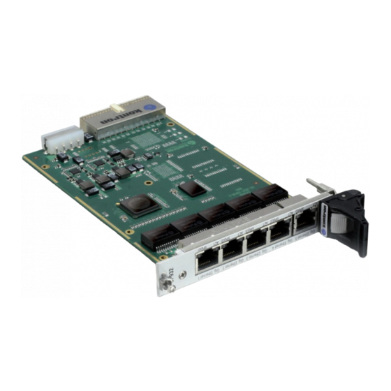
Ethernet channels, and with six Gigabit Ethernet channels. The five-channel variant is fitted with an ATX power connector which enables the CP932 to be used as a standalone ap- plication. The six-channel variant is equipped with an additional Gigabit Ethernet channel which enables the network traffic to be effected via the CompactPCI interface. -
Page 21: Board-Specific Information
• One five-port or eight-port Gigabit Ethernet switch, depending on the variant • One CompactPCI connector • One 4-pin ATX power connector to be used optionally as power source if the CP932 is used as a standalone application (only on the five-channel variant) •... -
Page 22: Board Diagrams
MAC/PHY 1.8V Intel 82541PI 3.3V CompactPCI Connector 4-Pin ATX Con. Only on the five-channel variant of the CP932 Only on the six-channel variant of the CP932 Page 1 - 6 © 2005 Kontron Modular Computers GmbH ID 30048, Rev. 01... -
Page 23: Front Panel
CP932 Introduction 1.3.2 Front Panel Figure 1-2: CP932 Front Panel LEGEND: CP 932 ACT LED (Green) • ACT ON: Ethernet Link • ACT OFF: No Ethernet Link • ACT BLINKING: Ethernet Activity SPEED LED (Green/Yellow) • SPEED ON (green): 100 Mbit •... -
Page 24: Board Layout
Figure 1-3: Board Layout of the Five-Channel Variant MAGNETICS Switch Conroller PHY1 Figure 1-4: Board Layout of the Six-Channel Variant MAGNETICS Switch Conroller PHY1 PHY2 PCI GbE Controller MAGNETICS Page 1 - 8 © 2005 Kontron Modular Computers GmbH ID 30048, Rev. 01... -
Page 25: Technical Specifications
• universal signaling: 3.3 V or 5 V V(I/O) • PCI interrupt INTA# Front Panel Connectors • five, 8-pin, female, RJ45 connector(s) • The CP932 supports up to five channels of full or half duplex 10Base-T, 100Base-TX, 1000-Base-T Ethernet operation with up External to 100 meters cable length. -
Page 26: Applied Standards
CP932 Table 1-2: CP932 Main Specifications (Continued) GROUP TYPE DESCRIPTION Jumpers No jumpers must be set. The CP932 is a Plug&PLay card. Power Requirements Board power supply: 5 V ±5% Power Consumption See Table 5-4 for details. Temperature Range Operational: 0ºC to +70ºC... -
Page 27: Functional Description
CP932 Functional Description Chapter Functional Description ID 30048, Rev. 01 © 2005 Kontron Modular Computers GmbH Page 2 - 1... - Page 28 Functional Description CP932 This page has been intentionally left blank. Page 2 - 2 © 2005 Kontron Modular Computers GmbH ID 30048, Rev. 01...
-
Page 29: General Information
CP932 Functional Description Functional Description The following chapters present more detailed, board level information about the CP932 Gigabit Ethernet switch whereby the board components and their basic functionality are discussed in general. General Information The CP932 is comprised basically of the following: •... -
Page 30: Thermal Aspects
On the Broadcom BCM5388 switch controller, the remaining four ports feature a standard RGMII interface to allow connection to the external 10/100/1000 Mbit/s PHY transceivers. The six-channel variant of the CP932 uses only two of the remaining four ports of the Broad- com BCM5388 switch controller. -
Page 31: Pci Gigabit Ethernet Controller (Integrated Nic)
Functional Description PCI Gigabit Ethernet Controller (Integrated NIC) The six-channel variant of the CP932 provides one onboard NIC Gigabit Ethernet channel used with the Intel 82541PI PCI Gigabit Ethernet controller. This chip provides, on the one hand, a PCI interface communicating with the host over the CompactPCI backplane and, on the other hand, a ready-to-use Gigabit Ethernet channel on copper PHY level. -
Page 32: Board Interfaces
The Ethernet connectors are realized as RJ45 connectors. The interfaces provide automatic detection and switching between 10Base-T, 100Base-TX and 1000Base-T data transmission. Auto-wire switching for crossed cables is also supported. Page 2 - 6 © 2005 Kontron Modular Computers GmbH ID 30048, Rev. 01... -
Page 33: Pinouts Of J4A - J4D And J5 Based On The Implementation
1000BASE-T connection. When green it indicates a 100Base-TX connection and when yellow it indicates a 1000Base-T connection. When not lit and the ACT LED is active, the connection is operating at 10Base-T. ID 30048, Rev. 01 © 2005 Kontron Modular Computers GmbH Page 2 - 7... -
Page 34: Compactpci Interface
2.5.2 CompactPCI Interface The CP932 is equipped with one 2 mm x 2 mm pitch, 32-bit, female, CompactPCI connector, J1, with support for PCI bus signals, arbitration, clock and power. The CP932 is designed for a CompactPCI bus architecture. The CompactPCI standard is elec- trically identical to the PCI local bus. -
Page 35: Atx Power Interface
The 4-pin ATX power connector is only available on the five-channel variant of the CP932 and is used for connecting the ATX power supply to the CP932. This connector may only be used if the CompactPCI connector, J1, is not connected to the power supply. - Page 36 Functional Description CP932 This page has been intentionally left blank. Page 2 - 10 © 2005 Kontron Modular Computers GmbH ID 30048, Rev. 01...
-
Page 37: Installation
CP932 Installation Chapter Installation ID 30048, Rev. 01 © 2005 Kontron Modular Computers GmbH Page 3 - 1... - Page 38 Installation CP932 This page has been intentionally left blank. Page 3 - 2 © 2005 Kontron Modular Computers GmbH ID 30048, Rev. 01...
-
Page 39: Hardware Installation
Installation Installation The CP932 has been designed for easy installation. However, the following standard precau- tions, installation procedures, and general information must be observed to ensure proper in- stallation and to preclude damage to the board or injury to personnel. -
Page 40: Installation Procedures
(If the handle does not move, it is not unlocked. Repeat the un- locking procedure above and try again. Do not use force!) Software Installation Installation of the CP932 driver software is a function of the application operating system. For further information, refer to the appropriate software documentation. Page 3 - 4 ©... -
Page 41: Configuration
CP932 Configuration Chapter Configuration ID 30048, Rev. 01 © 2005 Kontron Modular Computers GmbH Page 4 - 1... - Page 42 Configuration CP932 This page has been intentionally left blank. Page 4 - 2 © 2005 Kontron Modular Computers GmbH ID 30048, Rev. 01...
- Page 43 CP932 Configuration Configuration The CP932 is designed for plug-and-play operation, and, as such, it does not have any user configurable board settings which are required for operation. ID 30048, Rev. 01 © 2005 Kontron Modular Computers GmbH Page 4 - 3...
- Page 44 Configuration CP932 This page has been intentionally left blank. Page 4 - 4 © 2005 Kontron Modular Computers GmbH ID 30048, Rev. 01...
- Page 45 CP932 Power Considerations Chapter Power Considerations ID 30048, Rev. 01 © 2005 Kontron Modular Computers GmbH Page 5 - 1...
- Page 46 Power Considerations CP932 This page has been intentionally left blank. Page 5 - 2 © 2005 Kontron Modular Computers GmbH ID 30048, Rev. 01...
-
Page 47: System Power
The following table specifies the ranges for the different input power voltages within which the board is functional. The CP932 is not guaranteed to function if the board is not operated within the prescribed limits. Table 5-2: DC Operational Input Voltage Ranges... -
Page 48: Power Supply Units
CP932 Power Supply Units Power supplies for the CP932 must be specified with enough reserve for the remaining system consumption. In order to guarantee a stable functionality of the system, it is recommended to provide more power than the system requires. An industrial power supply unit should be able to provide at least twice as much power as the entire system requires. -
Page 49: Voltage Ramp
5.4.1 Voltage Ramp Power supplies must comply with the following guidelines, in order to be used with the CP932. • Beginning at 10% of the nominal output voltage, the voltage must rise within > 0.1 ms to < 20 ms to the specified regulation range of the voltage. Typically: >... -
Page 50: Recommended Operating Conditions
When a PSU of this type is used, it will not power up correctly and the CP932 may hang up. The solution is to use an industrial PSU or to add more load to the system. -
Page 51: Power Consumption Of The Cp932
CP932 Power Considerations Power Consumption of the CP932 Table 5-4: Power Consumption of the CP932 POWER CONSUMPTION (typical) CP932 VARIANT OPERATIONAL CONFIGURATION NO LINK 10 MBit/s 100 MBit/s 1000 MBit/s five-channel variant 1.6W 1.3W 1.9W 4.6W six-channel variant 3.7W 3.4W 4.0W... - Page 52 Power Considerations CP932 This page has been intentionally left blank. Page 5 - 8 © 2005 Kontron Modular Computers GmbH ID 30048, Rev. 01...
Need help?
Do you have a question about the CP932 and is the answer not in the manual?
Questions and answers