
Subscribe to Our Youtube Channel
Related Manuals for Kontron MicroTCA AM5901


Summary of Contents for Kontron MicroTCA AM5901
- Page 1 » User Guide « AM5901 MicroTCA™ Carrier Hub Double, Full-size AMC Form Factor Doc. ID: 1032-0648, Rev. 1.0 August 3, 2009 If it’s embedded, it’s Kontron.
-
Page 2: Imprint
Disclaimer Copyright © 2009 Kontron AG. All rights reserved. All data is for information purposes only and not guaranteed for legal purposes. Information has been carefully checked and is believed to be accurate; however, no responsibility is assumed for inaccuracies. Kontron and the Kontron logo and all other trademarks or registered trademarks are the property of their respective own- ers and are recognized. -
Page 3: Table Of Contents
AM5901 Preface Table of Contents Revision History ......................ii Imprint ........................ii Disclaimer ........................ii Table of Contents ...................... iii List of Tables ......................vii List of Figures ......................ix Proprietary Note ......................xi Trademarks .......................xi Environmental Protection Statement .................xi Explanation of Symbols ................... xii For Your Safety ....................... - Page 4 Preface AM5901 2.2.1 Front Panel LEDs ................2 - 4 2.2.2 Module Handle ................2 - 6 2.2.3 General Purpose DIP Switch ............2 - 7 2.2.4 Debug Interface ................2 - 7 2.2.5 Management Ports ................2 - 7 2.2.5.1 Management Serial Port ............2 - 7 2.2.5.2 Management Ethernet Interface (10Base-T) ......2 - 8 2.2.6...
- Page 5 AM5901 Preface 4.2.2 Power Requirements ..............4 - 4 4.2.2.1 Payload Power ............... 4 - 4 4.2.2.2 Payload and Management Voltage Ramp ......4 - 4 4.2.2.3 Management Power Consumption ......... 4 - 5 4.2.3 Payload Power Consumption of the AM5901 ......... 4 - 5 4.2.4 IPMI FRU Payload Power Consumption .........
- Page 6 Preface AM5901 This page has been intentionally left blank. Page vi ID 1032-0648, Rev. 1.0...
-
Page 7: List Of Tables
AM5901 Preface List of Tables System Relevant Information ..............1 - 5 AM5901 Main Specifications ..............1 - 9 Standards ....................1 - 11 Related Publications ................1 - 12 Module LEDs Function ................2 - 5 User LED 0 Function ................2 - 5 Fabric [A] Link LEDs 12..1 Function ............ - Page 8 Preface AM5901 This page has been intentionally left blank. Page viii ID 1032-0648, Rev. 1.0...
-
Page 9: List Of Figures
AM5901 Preface List of Figures AM5901 Functional Block Diagram ............1 - 6 AM5901 Front Panel ................1 - 7 AM5901 Board Layout (Top View) ............1 - 8 AM5901 Board Layout (Bottom View) ............1 - 8 Front Panel LEDs ................... 2 - 4 Module Handle Positions ............... - Page 10 Preface AM5901 This page has been intentionally left blank. Page x ID 1032-0648, Rev. 1.0...
-
Page 11: Proprietary Note
Preface Proprietary Note This document contains information proprietary to Kontron. It may not be copied or transmit- ted by any means, disclosed to others, or stored in any retrieval system or media without the prior written consent of Kontron or one of its authorized agents. -
Page 12: Explanation Of Symbols
Preface AM5901 Explanation of Symbols Caution, Electric Shock! This symbol and title warn of hazards due to electrical shocks (> 60V) when touching products or parts of them. Failure to observe the pre- cautions indicated and/or prescribed by the law may endanger your life/health and/or result in damage to your material. -
Page 13: For Your Safety
However, the life expectancy of your product can be drastically reduced by improper treatment during unpacking and installation. Therefore, in the interest of your own safety and of the correct operation of your new Kontron product, you are requested to conform with the following guidelines. -
Page 14: General Instructions On Usage
General Instructions on Usage In order to maintain Kontron’s product warranty, this product must not be altered or modified in any way. Changes or modifications to the device, which are not explicitly approved by Kontron and described in this manual or received from Kontron’s Technical Support as a special han- dling instruction, will void your warranty. -
Page 15: Two Year Warranty
As a result, the products are sold “as is,” and the responsibility to ensure their suit- ability for any given task remains that of the purchaser. In no event will Kontron be liable for direct, indirect or consequential damages resulting from the use of our hardware or software products, or documentation, even if Kontron were advised of the possibility of such claims prior to the purchase of the product or during any period since the date of its purchase. - Page 16 Preface AM5901 This page has been intentionally left blank. Page xvi ID 1032-0648, Rev. 1.0...
-
Page 17: Introduction
AM5901 Introduction Chapter Introduction ID 1032-0648, Rev. 1.0 Page 1 - 1... - Page 18 Introduction AM5901 This page has been intentionally left blank. Page 1 - 2 ID 1032-0648, Rev. 1.0...
-
Page 19: Board Overview
AM5901 Introduction Introduction Board Overview The AM5901 is a MicroTCA™ Carrier Hub (MCH) implemented in the form factor of a Double, Full-size Advanced Mezzanine Card (AMC) Module with a single tongue. It combines the control and management infrastructure and the interconnect fabric resources needed to sup- port up to twelve AMC modules, up to two cooling units and up to four power modules in a MicroTCA™... -
Page 20: Board-Specific Information
Introduction AM5901 Board-Specific Information Due to the comprehensive features of the AM5901, such as high-performance switching fabric and flexible interconnect topologies, this MCH provides a highly scalable solution not only for a wide range of telecom and data network applications, but also for highly integrated industrial environment applications with solid mechanical interfacing. -
Page 21: System Relevant Information
AM5901 Introduction System Relevant Information The following system relevant information is general in nature but should still be considered when developing applications using the AM5901. Table 1-1: System Relevant Information SUBJECT INFORMATION Hardware Requirements The AM5901 can be installed on any MicroTCA™ backplane that supports the fol- lowing MCH interconnection: •... -
Page 22: Am5901 Functional Block Diagram
Introduction AM5901 Figure 1-1: AM5901 Functional Block Diagram Page 1 - 6 ID 1032-0648, Rev. 1.0... -
Page 23: Front Panel
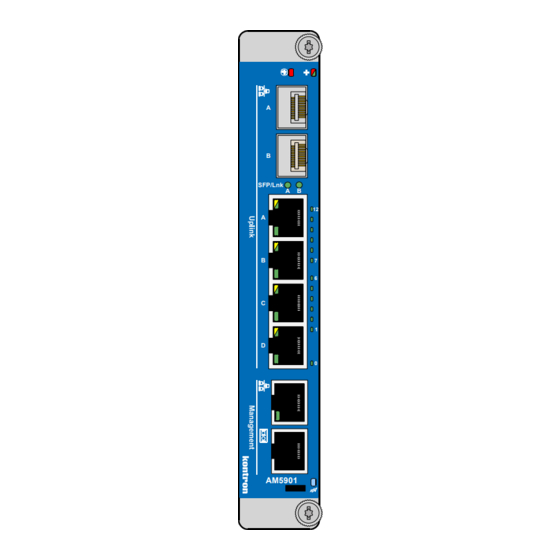
AM5901 Introduction 1.4.2 Front Panel Figure 1-2: AM5901 Front Panel Module LEDs LED1 (red): Out-of-Service LED LED2 (red/green/amber): Health LED HS LED (blue): The hot swap indicator provides basic feedback to the user on the hot swap state of the module. The HS LED states are off, short blink, long blink, and on. -
Page 24: Board Layouts
Introduction AM5901 1.4.3 Board Layouts Figure 1-3: AM5901 Board Layout (Top View) SFP A SFP B SFP/Lnk LEDs GbE A GbE B GbE PHY GbE C Logic GbE D Mag. Switch Temperature Sensor Figure 1-4: AM5901 Board Layout (Bottom View) Switch Page 1 - 8 ID 1032-0648, Rev. -
Page 25: Technical Specification
AM5901 Introduction Technical Specification Table 1-2: AM5901 Main Specifications FEATURES SPECIFICATIONS MCMC NXP® LPC2368 microcontroller • 70 MHz ARM7 CPU • One Ethernet interface for shelf mangagement purposes • IPMI • Watchdog timer • I²C busses for IPMB usage • Command line interface Fabric [A] Broadcom BCM5396 Gigabit Ethernet switch... - Page 26 Introduction AM5901 Table 1-2: AM5901 Main Specifications (Continued) FEATURES SPECIFICATIONS • Module LEDs LED1 (red): Out-of-Service LED • LED2 (red/green/amber): Health LED • HS LED (blue): The hot swap indicator provides basic feed- back about the hot swap state of the module. The HS LED states are off, short blink, long blink, and on.
-
Page 27: Standards
AM5901 Introduction Standards This Kontron MCH board complies with the requirements of the following standards. Table 1-3: Standards COMPLIANCE TYPE STANDARD TEST LEVEL Emission EN55022 EN61000-6-3 EN300386 Immission EN55024 EN61000-6-2 EN300386 Electrical Safety EN60950-1 Mechanical Mechanical Dimensions IEEE 1101.10 Environmental and... -
Page 28: Related Publications
INF-8074i Specification for SFP (Small Formfactor Pluggable) Transceiver, Rev. 1.0, May 12, 2001 PICMG® AMC.0, Advanced Mezzanine Card Specification R2.0 IPMI IPMI - Intelligent Platform Management Interface Specification, v1.5 All Kontron products Product Safety and Implementation Guide, ID 1021-9142 Page 1 - 12 ID 1032-0648, Rev. 1.0...
Need help?
Do you have a question about the MicroTCA AM5901 and is the answer not in the manual?
Questions and answers