
Subscribe to Our Youtube Channel
Related Manuals for WEG CFW11M G2 Series


Summary of Contents for WEG CFW11M G2 Series
- Page 1 Motors I Automation I Energy I Transmission & Distribution I Coatings Frequency Inverter CFW11M G2 User's Manual...
- Page 3 User's Manual Series: CFW-11M G2 Language: English Document: 10004198735 / 00 Models: 634...3012 A/380...480 V 496...2356 A/500...600 V 439...2585 A/660...690 V Publication Date: 06/2018...
- Page 4 Summary of Reviews The table below describes all revisions made to this manual. Version Review Description First edition...
-
Page 5: Table Of Contents
Contents 1 SAFETY INSTRUCTIONS ............... 1-1 1.1 SAFETY NOTICES IN THE MANUAL ....................1-1 1.2 SAFETY WARNINGS ON THE PRODUCT ..................1-1 1.3 PRELIMINARY RECOMMENDATIONS ..................1-2 2 GENERAL INFORMATION ..............2-1 2.1 ABOUT THE MANUAL ........................2-1 2.2 TERMS AND DEFINITIONS USED IN THE MANUAL ..............2-1 2.3 ABOUT THE CFW-11M G2 ...................... - Page 6 Contents 3.4 INSTALLATIONS ACCORDING TO THE EUROPEAN ELECTROMAGNETIC COMPATIBILITY DIRECTIVE ......................3-46 3.4.1 Conformal Installation ......................3-46 3.4.2 Definition of the Standards ....................3-47 3.4.3 Emission and Immunity Levels Met .................. 3-48 4 HMI......................4-1 4.1 INTEGRAL KEYPAD - HMI-CFW11M G2 ..................4-1 4.2 PARAMETER STRUCTURE ......................
-
Page 7: Safety Instructions
Safety Instructions 1 SAFETY INSTRUCTIONS This manual contains the necessary information for the correct use of the CFW-11M G2 frequency inverter. Only trained and qualified personnel should attempt to install, start-up, and troubleshoot this type of equipment. 1.1 SAFETY NOTICES IN THE MANUAL The following safety warnings are used in this manual: DANGER! The procedures recommended in this warning have the purpose of protecting the user against dead,... -
Page 8: Preliminary Recommendations
Electronic boards have components sensitive to electrostatic discharges. Do not touch directly on components or connectors. If necessary, touch the grounded metallic frame before or use an adequate grounded wrist strap. Do not perform any withstand voltage test! If necessary, consult WEG. 1-2 | CFW-11M G2... - Page 9 Safety Instructions NOTE! Frequency inverter may interfere with other electronic equipment. In order to reduce these effects, take the precautions recommended in the Chapter 3 INSTALLATION AND CONNECTION on page in order to minimize those effects. NOTE! Read the user manual completely before installing or operating the inverter. DANGER! Crushing hazard In order to ensure safety in load lifting applications, electric and/or mechanical devices must be...
- Page 10 Safety Instructions 1-4 | CFW-11M G2...
-
Page 11: General Information
The user guides are also provided in a hard copy along with the kit/accessories. The other manuals are available at www.weg.net. A printed copy of the files available on WEG’s website can be requested at your local WEG dealer. - Page 12 General Information Where: N = number of the power units. = current of phase Y (U, V or W) of the power unit N (P0815 to P0829). = average current of phase Y. YAVG Rectifier: input circuit of the inverters which converts the AC input voltage into DC. Formed by thyristors or power diodes.
- Page 13 General Information Run/Stop: inverter function that when activated (Run) accelerates the motor with the acceleration ramp until reaching the speed reference, and when deactivated (Stop) decelerates the motor with the deceleration ramp down to stop. It can be commanded through a digital input programmed for that function or via serial communication. The HMI (Run) and (Stop) keys operate in a similar way.
-
Page 14: About The Cfw-11M G2
General Information Ω: ohms. 2.3 ABOUT THE CFW-11M G2 The CFW-11M G2 inverters are the second generation of the CFW-11M inverters. The main differences in relation to the previous generation are the following: Smaller. The CFW-11M G2 is shorter and slimmer than the CFW-11M, allowing the installation of 3 UP11 G2 in „... - Page 15 General Information 220 Vac power supply external fans 24 Vac power supply external fans UP11 3 Fans UP11 2 Fans UP11 1 Power unit IGBT'S Motor Fans DC supply Capacitor IGBT'S brank RFI Filter Feedback: - voltage - current ICUP Power Power supplies and interfaces between power and control...
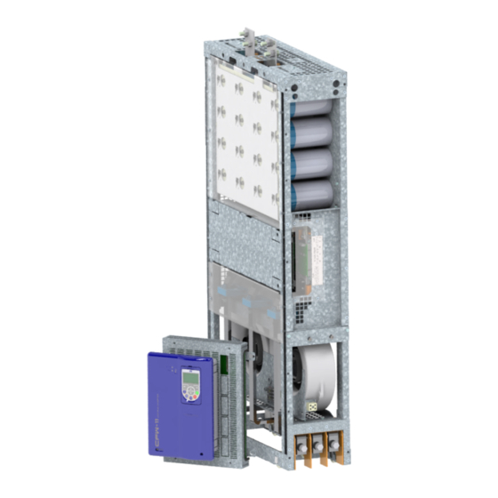
- Page 16 General Information Figure 2.2: Power Unit (UP11) Figure 2.3: Control Unit (UC11) 2-6 | CFW-11M G2...
-
Page 17: Identification Label For The Uc11 G2
The inclusion of a current transformer (CT) in the drive for the output short-circuit to the ground protection is not necessary because each UP11 has its own internal protection. 2.4 IDENTIFICATION LABEL FOR THE UC11 G2 The UC11 nameplate is located on the control rack. WEG part number UC11 model Serial number Manufacturing date (30... -
Page 18: Identification Label For The Up11 G2
60s/3s 570 A / 680 A 50/60 Hz 0-200 Hz FABRICADO NO BRASIL HECHO EN BRASIL MADE IN BRAZIL WEG, CP420 - 89256-900 Jaraguá do Sul - Brazil UP11-01 G2 13353741 12 0 SERIAL#: 8888888888 Figure 2.6: UP11 G2 nameplate Nameplate Figure 2.7: Location of the Nameplates... -
Page 19: How To Specify The Model Of The Cfw-11M G2 (Smart Code)
General Information 2.6 HOW TO SPECIFY THE MODEL OF THE CFW-11M G2 (SMART CODE) In order to specify the model of the CFW-11M G2, replace the smart code values with the desired rated supply voltage and rated output current in the respective fields for operation under normal duty (ND), as shown in the example of Table 2.1 on page 2-9. -
Page 20: Receipt And Storage
General Information E.g.: CFW11MG21205T4OYZ corresponds to a CFW-11M G2 three-phase inverter of 1205 A, with input supply voltage from 380 V to 480 V, with optional safety stop. The options for the inverter rated current under normal duty (ND) are in Table 3.2 on page 2-10, according to the inverter rated output voltage. -
Page 21: Installation And Connection
Installation and Connection 3 INSTALLATION AND CONNECTION This chapter provides information on installing and wiring the CFW-11M G2. The instructions and guidelines listed in this manual shall be followed to guarantee personnel and equipment safety, as well as the proper operation of the inverter. - Page 22 3.0 m 3.6 m 1251 1668 1292 2085 1615 Table 3.4: Cable set items WEG Item Cable Set 13555095 2.5 m Cables 13555150 3.0 m Cables 13555151 3.6 m Cables The other components of the drive are under the responsibility of the panel builder. Among those components, we may point out the input rectifier, power busbar, pre-charge circuit, panel fans, protection fuses, input reactance, etc.
-
Page 23: Lifting
Installation and Connection 3.1.3 Lifting Figure 3.1 on page 3-3 shows the position of the lifting lugs. Lifting lugs Front view Back View Figure 3.1: UP11 G2 lifting lugs CFW-11M G2 | 3-3... -
Page 24: Panel Ventilation
Installation and Connection 3.1.4 Panel Ventilation The efficiency of the panel ventilation depends on the equipment installed inside the panel, such as fans, air inlets and filters. The internal fan of the UP11 is not enough to cool the entire panel. Panel fan (when required) Air outlets Air outlet... - Page 25 Installation and Connection 354.7 [13.96] 30.1 [1.19] 119.7 [4.71] ø9.2 [0.36] ø9.2 [0.36] 582 [22.91] 678.8 [26.72] ø9.2 [0.36] 474.4 [18.68] Figure 3.3: Dimensions of Rack 2 G2 in mm [in] CFW-11M G2 | 3-5...
- Page 26 Installation and Connection 459.6 [18.1] 224.6[8.84] 30.1 [1.19] ø9.2 [0.36] ø9.2 [0.36] 582 [22.93] 678.8 [26.72] ø9.2 [0.36] 684.7 [26.96] Figure 3.4: Dimensions of Rack 3 G2 in mm [in] 3-6 | CFW-11M G2...
-
Page 27: Panel
Installation and Connection Figure 3.5: Insertion of the power modules into Rack 3 G2 3.1.6 Panel According to the quantity of UP11 G2 of the drive, minimum dimensions are necessary for the panels. Figure 3.6 on page 3-7, Figure 3.7 on page 3-8, Figure 3.8 on page 3-8 Figure 3.10 on page 3-8... - Page 28 Installation and Connection Panel Width At least 600 mm Panel Height At least 2000 mm Panel Depth At least 800 mm Weight Capacity 212 kg Figure 3.7: Data of the panel for drive with 2 UP11 G2 Panel Width At least 800 mm Panel Height At least 2000 mm Panel Depth...
- Page 29 Installation and Connection Figure 3.11: Column with 3 UP11 G2 installed Mounting of the UC11 at the panel door: Control rack with flange mounting and IPS1 module mounted at the bottom part of the door. The control rack is secured with four M3 screws (tightening torque: 0.5 Nm). ICUP Figure 3.12: Example of mounting of the control rack in the panel CFW-11M G2 | 3-9...
- Page 30 Installation and Connection ø 5.2 (4X) (7.48) (0.20) R8 (4x) (0.32) 186.5 (7.34) 93.3 (3.67) 7 (0.27) 7 (0.27) (0.43) Figure 3.13: Mounting of the control rack and necessary slots mm (in) [11.2] 283.6 [0.2] R4 (4x) Figure 3.14: Mounting of the base of the ICUP1 module (mm) The shield of the ICUP board is mounted with four screws M6 (recommended torque: 8.5 N.m).
-
Page 31: Electrical Installation
Active Front End (AFE) or a diode bridge rectifier with 6, 12, 18 pulses or more. The following items contain general directions on the sizing of a 6-pulse rectifier. For further information on multipulse rectifiers or AFE solution, contact WEG. 3.2.1.1 Sizing The main rectifier bridge is selected to comply with the nominal power of the drive. -
Page 32: Pre-Charge
Installation and Connection The harmonic input currents depend on the impedance values that are present in the rectifier input/output circuit. The addition of a line reactor and/or DC bus choke reduces the current harmonic content, providing the following advantages: Increased input power factor. „... - Page 33 Installation and Connection Rectifier UP11 G2 Line Reactor Motor Rede KPCR Stop XC1:22 220 Vac CC11 (DO1) external XC1:23 XC1:22 KPCR KPCR Figure 3.15: Pre-charge circuit example The CFW-11M G2 input rectifier can be supplied through a contactor or a motorized circuit breaker (represented by K1), whose command must be interlocked with the pre-charge contactor K(PCR) command.
-
Page 34: Harmonics Of The 6-Pulse Rectifier
Installation and Connection 3.2.1.4 Harmonics of the 6-Pulse Rectifier Table 3.6 on page 3-14, Figure 3.16 on page 3-14 Figure 3.17 on page 3-14 show the typical values of the harmonic content of the currents, Power Factor (PF) and THD (I) on the power supply, considering the 6-pulse rectifier. -
Page 35: Harmonics Of The 12-Pulse Rectifier
Installation and Connection 3.2.1.5 Harmonics of the 12-Pulse Rectifier Table 3.7 on page 3-15, Figure 3.18 on page 3-15 Figure 3.19 on page 3-15 show the typical values of the harmonic content of the currents, Power Factor and THD (I) on the power supply, considering the 12-pulse rectifier. Table 3.7: Individual harmonics, Power Factor and THD (I) typical for rated load in the output, 12-pulse rectifier Harmonic I (%) -
Page 36: Harmonics Of The 18-Pulse Rectifier
Installation and Connection 3.2.1.6 Harmonics of the 18-Pulse Rectifier Table 3.8 on page 3-16, Figure 3.20 on page 3-16 Figure 3.21 on page 3-16 show the typical values of the harmonic content of the currents, Power Factor and THD (I) on the power supply, considering the 18-pulse rectifier. Table 3.8: Individual harmonics, Power Factor and THD (I) typical for rated load in the output, 18-pulse rectifier Harmonic I (%) -
Page 37: Busbars
Installation and Connection NOTE! The harmonics shown in Item 3.2.1.4 Harmonics of the 6-Pulse Rectifier on page 3-14, Item 3.2.1.5 Harmonics of the 12-Pulse Rectifier on page 3-15 Item 3.2.1.6 Harmonics of the 18-Pulse Rectifier on page 3-16 are typical values and may vary according to the application. The data shown are valid for the following condition: Short circuit current of the transformer of 100000 symmetric Arms. - Page 38 Installation and Connection UC11 ICUP UP11 XC33 220 Vac 24 Vdc CC11 UP11 XC33 220 Vac 24 Vdc UP11 MOTOR XC33 220 Vac 24 Vdc Error_BR UP11 XC33 220 Vac 24 Vdc UP11 XC33 220 Vac 24 Vdc Figure 3.22: General wiring diagram 3-18 | CFW-11M G2...
-
Page 39: Power Connections
Installation and Connection 3.2.5 Power Connections Power supply DC Figure 3.23: Power and grounding connections ATTENTION! The protective earth of the motor must be connected to the panel ground. The fastening of the DC+ and DC- connections of the UP11 G2 is done with 4 screws M12X35 (tightening torque: 60 N.m);... - Page 40 Installation and Connection Figure 3.24: DC power supply terminals DC+: DC Link positive terminal. DC-: DC Link negative terminal. The U, V and W connections are made through 3 screws M12X45 (tightening torque: 60 N.m, see Figure 3.25 on page 3-21).
- Page 41 Installation and Connection Figure 3.25: U, V, W and grounding terminals U, V and W: Motor connection. : Grounding connection. For a better current distribution between the UP11, it is recommended that their output connections be interconnected through a single paralleling busbar. The length of the cables between the UP11 and the paralleling busbar must be as short as possible.
-
Page 42: Input Connections
Installation and Connection ATTENTION! The motor cables must be distributed as evenly as possible on the connection to the paralleling busbar, as in the example shown in Figure 3.26 on page 3-22. Distance "L" must be kept constant. DC Power Supply Grounding busbar... - Page 43 8-2. The Figure 3.28 on page 3-23 shows an example of flexible braid used by WEG, using a fuse on DC+ and another on DC-. F1 DC+ Figure 3.27: Side view of the connections of the flexible braids and fuses ø...
-
Page 44: Output Connections
Installation and Connection 3.2.7 Output Connections ATTENTION! The inverter has an electronic motor overload protection that must be adjusted according to the driven motor. When several motors are connected to the same inverter, install individual overload relays for each motor. ATTENTION! The motor overload protection available on the CFW-11M G2 complies with IEC609047-4-2 and UL508C, notice the information below:... -
Page 45: Grounding Connections
Installation and Connection NOTE! The magnetic field created by the current circulation in these cables may induce currents in nearby metal parts, heating them, and cause additional electrical losses. Therefore, keep the three cables (U, V, W) always together. Shielded Cables: They are mandatory when it is necessary to comply with the electromagnetic compatibility directive (89/336/ „... -
Page 46: It Networks
Installation and Connection ATTENTION! The neutral conductor of the network must be solidly grounded; however, this conductor must not be used to ground the inverter. DANGER! The inverter must be obligatorily connected to a protective ground (PE). Observe the following: Connect the grounding points of the inverter to a specific grounding rod, or specific grounding „... -
Page 47: Terminals Recommended For Power Cables
Installation and Connection 3.2.10 Terminals Recommended for Power Cables Cable Gauge Number of Screw Manufacturer Lug Terminal, Code Crimping Tool, Code Crimps Hollingsworth RM120-12 Hydraulic tool H6-500 Tool without die: MY29-3 or Y644 or Y81 Burndy (FCI) YA28L Tool+die: Y35 or Y750 / U29RT Hollingsworth RM150-12 Hydraulic tool H6-500... -
Page 48: Control Connections
Installation and Connection 3.2.12 Control Connections 3.2.12.1 UP11 G2 Connections UP11 Control Power Supply Connectors Fiber Optic Connector DB25 Figure 3.30: Control cable connection points on the UP11 G2 3-28 | CFW-11M G2... - Page 49 Installation and Connection XC6: Power supply 24 Vdc (UP11 G2 control) Fiber optics connectors (connections to the ICUP board) XC40: Connector DB25 (connection to the ICUP board) Figure 3.31: Identification of the control connections of the UP11 G2 The electronics of the UP11 G2 is powered via connector XC6, located on the IUP board; it is described in Figure 3.12 on page 3-9.
- Page 50 Installation and Connection Fan supply terminals Figure 3.32: Fan supply terminals Table 3.14: Specification of the fan power supply of the fans Voltage Frequency Current 220 Vac 50 / 60 Hz 4 Aca 3-30 | CFW-11M G2...
-
Page 51: Uc11 G2 Connections
Control Rack switches connectors reserved (safety stop) S1 and S2 for WEG use Figure 3.33: ICUP board connection points The control rack is powered via connector XC9, located on the ICUP board; it is described in Table 3.14 on page 3-30. - Page 52 Installation and Connection Figure 3.34: DIP switches S1 and S2 detail Table 3.17: DIP switch S1:1 - S1:3 configuration Alternate Supply S1:3 S1:2 S1:1 Voltage 380 - 480 V 500 - 690 V Table 3.18: DIP switch S1:4 configuration S1:4 Operating Mode Normal Reduced Power...
- Page 53 Installation and Connection ICUP Motor XC33 220 V 24 Vdc power supply 220 Vac Error_BR ICUP shield fixing screw CX60 CX60 XC98 CV11 CC11 CC11 rack Rack CC11 grounding Panel grounding busbar Figure 3.35: Grounding diagram of the UP11 plus UC11, in case of only one UP11 The screws to fasten the ICUP shield to the panel must ensure the electrical contact between the shield and the panel for grounding.
- Page 54 Installation and Connection Figure 3.36: ICUP shield fastened to the panel The control rack must be grounded using a flat flexible braid with minimum width of 5 mm and minimum cross section of 3 mm² with standard FASTON terminal 6.35 mm (E.g.: TYCO 735075-0 and 180363-2) and lug terminal M4;...
-
Page 55: Cc11 Connections
Installation and Connection 3.2.12.3 CC11 Connections The control connections (analog inputs/outputs, digital inputs/outputs), must be made at the CC11 control board terminal strip XC1. Functions and typical connections are presented in Figure 3.39 on page 3-35 Figure 3.40 on page 3-36. - Page 56 Installation and Connection Terminal Factory Setting Function Specifications Strip Positive reference for Output voltage: +5.4 V, ±5 % REF+ potentiometer Maximum output current: 2 mA AI1+ Analog input # 1: Differential speed reference (remote) Resolution: 12 bits ≥5 kΩ Signal: 0 to 10 V (RIN = 400 kΩ) / 0 to 20 mA / 4 to 20 mA (RIN = 500 Ω) AI1- Maximum voltage: ±30 V Negative reference for...
- Page 57 Installation and Connection Slot 5 Slot 1 (white) Slot 2 (yellow) Slot 3 (green) Slot 4 Figure 3.41: Connector XC1 and switches to select the signal type of the analog inputs and outputs As the factory setting, the analog inputs and outputs are adjusted to operate in the 0 to 10 V range, but they can be changed by using the S1 DIP-switch.
- Page 58 Installation and Connection The correct connection of the cable shield is shown in Figure 3.43 on page 3-38. Insulate with tape Inverter Side Do not ground Figure 3.42: Conexão da blindagem Figure 3.43: Example of shield connection for the control wiring 4.
-
Page 59: Typical Control Connections
Installation and Connection 3.2.12.4 Typical Control Connections Control connection 1 - Run/Stop function controlled from the keypad (Local Mode). With this control connection it is possible to run the inverter in local mode with the factory default settings. This operation mode is recommended for first-time users, since no additional control connections are required. For the start-up in this operation mode, please follow instructions listed in Chapter 5 FIRST TIME POWER-UP AND START-UP on page... - Page 60 Installation and Connection Control connection 3 - Wire Run/Stop function. Enabling the Run/Stop function with 3-wire control. Parameters to be set: Set DI3 to START. „ P0265 = 6. „ Set DI4 to STOP. „ P0266 = 7. „ Set P0224 = 1 (DIx) for 3-wire control in Local mode. „...
- Page 61 Installation and Connection Control connection 4 - Forward/Reverse. Enabling the Forward/Reverse function. Parameters to be set: Set DI3 to Forward run. „ P0265 = 4. „ Set DI4 to Reverse run. „ P0266 = 5. „ When the Forward/Reverse function is set, it will be active either in Local or Remote mode. At the same time, the HMI keys will remain always inactive (even if P0224 = 0 or P0227 = 0).
-
Page 62: Safety Stop Function
Installation and Connection 3.3 SAFETY STOP FUNCTION The CFW11MG2...O...Y... inverters have the SRB board that provides the Safety Stop function. Through this board it is possible to control two safety relays (K1 and K2) which act directly on the power circuit, more specifically on the power supply of the IGBT activation fiber optics. -
Page 63: Installation
Installation and Connection NOTE! Inverter Safety Stop function is only one component of the safety control system of a machine and/or process. When inverter and its Safety Stop function is correctly used and with other safety components, it’s possible to fulfill the requirements of standard EN 954-1 / ISO 13849-1, Category 3 (machine safety) and IEC/EN 61508, SIL2 (safety control/signaling applied to processes and systems). -
Page 64: Operation
Installation and Connection 3.3.2 Operation 3.3.2.1 Truth Table Table 3.24: Safety Stop function operation STO1 Logic Level STO2 Logic Level Safety Stop (voltage between (voltage between Inverter Behavior Function XC25:1-2 terminals) XC25:3-4 terminals) Inverter remains in STO state and does not accept Active commands. -
Page 65: Periodical Test
Installation and Connection 3.3.2.4 Periodical Test Safety Stop function, alternatively safety stop inputs (STO1 and STO2), must be activated at least once a year for preventive maintenance purposes. Inverter power supply must be switched off and then on again before carrying out this preventive maintenance. -
Page 66: Technical Specifications
Switching current capacity: 100 mA per contact 3-45 Maximum switching delay between contacts: 100 ms Example Type/manufacturer: WEG/ Instrutech CPt-D 3.3.3.2 Operating Safety Characteristic Table 3.28: Operating safety characteristic Of the Safety Stop function which forces stopping and/or prevents the motor from restarting unintentionally,... -
Page 67: Definition Of The Standards
Installation and Connection Grounding of the inverter according to instructions of Item 3.2.8 Grounding Connections on page 3-25. „ 3.4.2 Definition of the Standards IEC/EN 61800-3: “Adjustable Speed Electrical Power Drives Systems”. Environments: First Environment: includes domestic premises. It also includes establishments directly connected without intermediate transformer to a low-voltage power supply network which supplies buildings used for domestic purposes. -
Page 68: Emission And Immunity Levels Met
Installation and Connection 3.4.3 Emission and Immunity Levels Met Table 3.29: Emission and immunity levels met EMC Phenomenon Basic Standard Level Emission Mains Terminal Disturbance Voltage IEC/EN61800-3 It depends on the inverter model and on the motor Frequency Range: 150 kHz to 30 MHz cable lenght. -
Page 69: Hmi
4 HMI This chapter contains the following information: HMI keys and functions. „ Indications on the display. „ Parameter structure. „ 4.1 INTEGRAL KEYPAD - HMI-CFW11M G2 The integral keypad can be used to operate and program (view/edit all parameters) of the CFW-11 inverter. The inverter keypad navigation is similar to the one used in cell phones and the parameters can be accessed in numerical order or through groups (Menu). - Page 70 Cover Remove the cover Press the cover and rotate it Cover for battery access counterclockwise Remove the battery with the HMI without the battery Install the new battery positioning it first at help of a screwdriver positioned the left side in the right side Press the battery for its insertion Put the cover back and rotate it clockwise...
- Page 71 Installation: The keypad can be installed or removed from the inverter with or without AC power applied to the inverter. Whenever the inverter is energized, the display goes to the monitoring mode. For the factory setting, a screen similar to Figure 4.3 on page 4-3 (a) will be shown.
-
Page 72: Parameter Structure
4.2 PARAMETER STRUCTURE When the right soft key ("MENU") is pressed in the monitoring mode, the display shows the first 4 groups of parameters. An example of how the groups of parameters are organized is presented in Table 4.1 on page 4-4. -
Page 73: First Time Power-Up And Start-Up
First Time Power-Up and Start-Up 5 FIRST TIME POWER-UP AND START-UP This chapter explains: Check and prepare the inverter before power-up. „ Power-up the inverter and check the result. „ Set the inverter for the operation in the V/f mode based on the power supply and motor information by using „... -
Page 74: Start-Up
First Time Power-Up and Start-Up 12. Mechanically uncouple the motor from the load. If the motor cannot be uncoupled, make sure that the chosen direction of rotation (forward or reverse) will not result in personnel injury and/or equipment damage. 13. Command the drive, perform the DC link pre-charge and close the main contactor/circuit breaker. 14. - Page 75 First Time Power-Up and Start-Up The use of the Oriented Start-up routine for setting the inverter parameters may lead to the automatic modification of other internal parameters and/or variables of the inverter During the Oriented Start-up routine, the message “Config” will be displayed at the left top corner of the keypad. Step Action/Result Display Indication...
-
Page 76: Setting Of The Basic Application Parameters
First Time Power-Up and Start-Up Step Action/Result Display Indication Step Action/Result Display Indication - At this point the Oriented - This parameter will only be Config 0rpm Config 0rpm Start-up routine starts visible if the encoder board Idioma Potencia Nom. Motor and the "Config"... - Page 77 First Time Power-Up and Start-Up Step Action/Result Display Indication Step Action/Result Display Indication - Monitoring mode - Group "04 BASIC Ready 0rpm Ready 0rpm - Press "Menu" (right soft APPLICATION" is selected 01 GRUPOS PARAMETROS key) - Press "Select" 02 START-UP ORIENTADO 03 PARAM.
- Page 78 First Time Power-Up and Start-Up Table 5.1: Parameters comprised in the basic application group Setting Factory User Parameter Name Description Range Setting Setting P0100 Acceleration time - Defines the time to linearly accelerate from 0 up to the 0.0 to 999.0 s 20.0 s maximum speed (P0134) - If set to 0.0 s, it means no acceleration ramp...
- Page 79 First Time Power-Up and Start-Up Table 5.2: Main read only parameters Parameter Description Setting Range Parameter Description Setting Range P0001 Speed Reference 0 to 18000 rpm P0069 Fifth Fault Time 00:00 to 23:59 P0002 Motor Speed 0 to 18000 rpm P0070 Sixth Fault 0 to 999...
-
Page 80: Setting Date And Time
First Time Power-Up and Start-Up 5.3 SETTING DATE AND TIME Step Action/Result Display Indication Step Action/Result Display Indication Monitoring mode - Once the setting of P0199 Ready 0rpm Ready 0rpm - Press "Menu" (right soft is over, the Real Time Clock Minutos key) is now updated... -
Page 81: Flash Memory Module
First Time Power-Up and Start-Up Install the SuperDrive G2 software to control motor speed, view, or edit inverter parameters through a personal computer (PC). Basic procedures for transferring data from the PC to the inverter: 1. Install the SuperDrive G2 software on the PC. 2. -
Page 82: Operation With A Reduced Number Of Power Units
First Time Power-Up and Start-Up Whenever the inverter is powered up, this program is transferred to the RAM memory located in the inverter control board and executed. Refer to the CFW-11 programming manual and to SoftPLC manual for further details. ATTENTION! Before installing or removing the FLASH memory module, disconnect the inverter power supply and wait for the complete discharge of the capacitors. - Page 83 First Time Power-Up and Start-Up 14. Connect the drive power source. UC11 ICUP UP11 XC33 220 Vac 24 Vdc CC11 UP11 XC33 220 Vac 24 Vdc UP11 MOTOR XC33 220 Vac 24 Vdc Error_BR UP11 XC33 220 Vac 24 Vdc UP11 XC33 220 Vac...
- Page 84 First Time Power-Up and Start-Up UC11 ICUP UP11 XC33 220 Vac 24 Vdc CC11 UP11 XC33 220 Vac 24 Vdc UP11 MOTOR XC33 220 Vac 24 Vdc Error_BR UP11 XC33 220 Vac 24 Vdc UP11 XC33 220 Vac 24 Vdc Figure 5.7: Moving the control connections on the ICUP board 5-12 | CFW-11M G2...
-
Page 85: Troubleshooting And Maintenance
Troubleshooting and Maintenance 6 TROUBLESHOOTING AND MAINTENANCE This chapter presents: The list of all faults and alarms. „ Most probable causes for each fault and alarm. „ The list of the most common problems and corrective actions. „ Instructions for periodical inspections of the product and preventive maintenance. „... -
Page 86: Faults, Alarms And Possible Causes
Troubleshooting and Maintenance 6.2 FAULTS, ALARMS AND POSSIBLE CAUSES Table 6.1: Faults, alarms and possible causes Fault/Alarm Description Possible Causes F020: Undervoltage on the 24Vdc power supply that Voltage on the power supply below 22.8 Vdc. „ 24Vdc Power Supply feeds the control. - Page 87 Alarm that indicates error of access to the Anybus- Anybus-CC module defective, not recognized or „ Anybus Access Error CC communication module. incorrectly installed. Conflict with WEG optional board. „ A133: Alarm of power supply missing on the CAN Broken or loose cable. „...
- Page 88 Safety Stop Relay (STO1 or STO2). One of the relays is defective. „ F161: Refer to the programming manual of the PLC11-01 module available on www.weg.net. Timeout PLC11 CFW-11 A162: Incompatible PLC Firmware A163: It indicates that AI1 current reference (4-20 mA or Cable of AI1 broken.
- Page 89 Troubleshooting and Maintenance Fault/Alarm Description Possible Causes F182: Fault in the output pulse feedback. Defect on the internal circuits of the inverter. „ Pulse Feedback Fault F183: Overtemperature related to IGBT overload High ambient temperature around the inverter. „ IGBTs Overload +Temperature protection.
- Page 90 Troubleshooting and Maintenance Fault/Alarm Description Possible Causes F239: It indicates interruption in the communication Check if the network master is correctly configured „ „ Offline Profibus DP Interface between the DP Profibus network master and and operating properly. the inverter. Check the network installation in general –...
- Page 91 Troubleshooting and Maintenance Fault/Alarm Description Possible Causes A321: Alarm of high temperature measured on the High ambient temperature (> 45 °C (113 °F)) and „ High Temperature temperature sensor (NTC) of IGBT of phase V of high output current. IGBT V B3 book 3.
- Page 92 Troubleshooting and Maintenance Fault/Alarm Description Possible Causes A345: Alarm of overload on the IGBT of phase U of High current in the inverter output (refer to Figure „ High Load IGBT U B1 book 1. 8.1 on page 8-3). F346: Fault of overload on the IGBT of phase U of book Overload on IGBT U B1 A348:...
- Page 93 Troubleshooting and Maintenance Fault/Alarm Description Possible Causes A390: Alarm of current imbalance of phase U book 1. Poor electrical connection between the DC link „ Current Imbalance It indicates an imbalance of 20 % in the current and the power unit. Phase U B1 distribution between this phase and the smallest Poor electrical connection between the power unit...
- Page 94 Troubleshooting and Maintenance Fault/Alarm Description Possible Causes A402: Alarm of current imbalance of phase U book 5. Poor electrical connection between the DC link „ Current Imbalance It indicates an imbalance of 20 % in the current and the power unit. Phase U B5 distribution between this phase and the smallest Poor electrical connection between the power unit...
-
Page 95: Solutions For The Most Frequent Problems
Troubleshooting and Maintenance NOTE! The range from P0750 to P0799 is destined to the SoftPLC applicative user faults and alarms. 6.3 SOLUTIONS FOR THE MOST FREQUENT PROBLEMS Table 6.2: Solutions for the most frequent problems Problem Point to be Verifid Corrective Action Motor does not start Incorrect wiring... -
Page 96: Preventive Maintenance
Do not touch the components or connectors directly. If necessary, first touch the grounded metallic frame or wear a ground strap. Do not perform any withstand voltage test! If necessary, consult WEG. The inverters require low maintenance when properly installed and operated Table 6.3 on page 6-12 presents the main procedures and time intervals for preventive maintenance. - Page 97 Troubleshooting and Maintenance Figure 6.2: Fan replacement Table 6.4: Recommended periodic inspections - every 6 months Component Part Problem Corrective Action Terminals, connectors Loose Screws Tighten Loose Connectors Fans/Cooling system Dirt on the fans Cleaning Abnormal acoustic noise Replace fan Refer to Figure 6.2 on page 6-13.
-
Page 98: Cleaning Instructions
Troubleshooting and Maintenance 6.5.1 Cleaning Instructions When it is necessary to clean the inverter, follow the instructions below: Ventilation system: 1. Disconnect the power supply of the inverter and wait for 10 minutes. 2. Remove the dust from the cooling air inlet by using a soft brush or a flannel. 3. -
Page 99: Accessories
ATTENTION! Only one module at a time can be fitted into each slot (1, 2, 3, 4 or 5). Table 7.1: Accessory models Identification WEG Item Parameters (material Name Description... -
Page 100: Accessories
Accessories Identification WEG Item Parameters (material Name Description Slot number) P0027 P0028 Anybus-CC accessories to install in Slot 4 11008158 DEVICENET-05 DeviceNet interface module ---- --xx (2)(3) 10933688 ETHERNET/IP-05 EtherNet/IP interface module ---- --xx (2)(3) 11550476 MODBUSTCP-05 Modbus TCP interface module... -
Page 101: Technical Specifications
Technical Specifications 8 TECHNICAL SPECIFICATIONS This chapter describes the technical specifications (electrical and mechanical) of the CFW-11M G2. 8.1 POWER DATA Power supply: Voltage tolerance: -15 % to +10 %. „ Maximum rated line voltage: 480 V for models with DC power supply of 436...750 Vdc, 600 V for models with „... - Page 102 Technical Specifications Table 8.1: Inverter technical specifications for rated switching frequencies Note: (1) Steady state rated current in the following conditions: - Indicated switching frequency. It is not possible to use the CFW-11M G2 inverter with switching frequency of 2.5 kHz, 5 kHz and 10 kHz. - Ambient temperature around the inverter as specified in Chapter 3 INSTALLATION AND CONNECTION on page 3-1.
- Page 103 Figure 8.1: (a) and (b) IGBT overload curves for ND and HD use (3) The motor powers are reference values; they are specified for WEG motors with 4 poles, 440 V for models with DC power supply 436...750 Vdc; 575 V for models with DC power supply of 574...970 Vdc and 690 V for models with DC power supply of 758...1150 Vdc.
-
Page 104: Electronics/General Data
Technical Specifications 8.2 ELECTRONICS/GENERAL DATA Table 8.2: General data regarding the inverter control and electronics Voltage source „ Control types: „ - V/f (scalar) - VVW: Voltage vector control - Vector control with encoder - Sensorless vector control (without encoder) Method - Vector control with encoder for permanent magnet motors (PMSM) PWM SVM (Space Vector Modulation) -
Page 105: Codes And Standards
Technical Specifications 8.2.1 Codes and Standards UL 508C - Power conversion equipment „ UL 840 - Insulation coordination including clearances and creepage distances for electrical equipment „ EN61800-5-1 - Safety requirements electrical, thermal and energy „ EN 50178 - Electronic equipment for use in power installations „... -
Page 106: Mechanical Data
Technical Specifications 8.3 MECHANICAL DATA The UP11 G2 module has a total mass of 94 Kg. Its dimensions are shown in Figure 8.2 on page 8-6. [2.829] 71.9 [0.591] [47.146] [1.614] 1197.5 Grounding Figure 8.2: Mechanical dimensions in mm [in] 8-6 | CFW-11M G2... - Page 107 Technical Specifications [7.091] 180.1 [8.389] 213.1 Figure 8.3: Control rack dimensions in mm [in] [10.2] [11.2] 283.6 [0.3] ø8 (4x) [11.8] 298.7 Figure 8.4: Dimensions of the ICUP board metal enclosure in mm [in] CFW-11M G2 | 8-7...
- Page 108 WEG Drives & Controls - Automação LTDA. Jaraguá do Sul - SC - Brazil Phone 55 (47) 3276-4000 - Fax 55 (47) 3276-4020 São Paulo - SP - Brazil Phone 55 (11) 5053-2300 - Fax 55 (11) 5052-4212 automacao@weg.net 14305853...
Need help?
Do you have a question about the CFW11M G2 Series and is the answer not in the manual?
Questions and answers