
Subscribe to Our Youtube Channel
Related Manuals for GE PanaFlow MV80


Summary of Contents for GE PanaFlow MV80
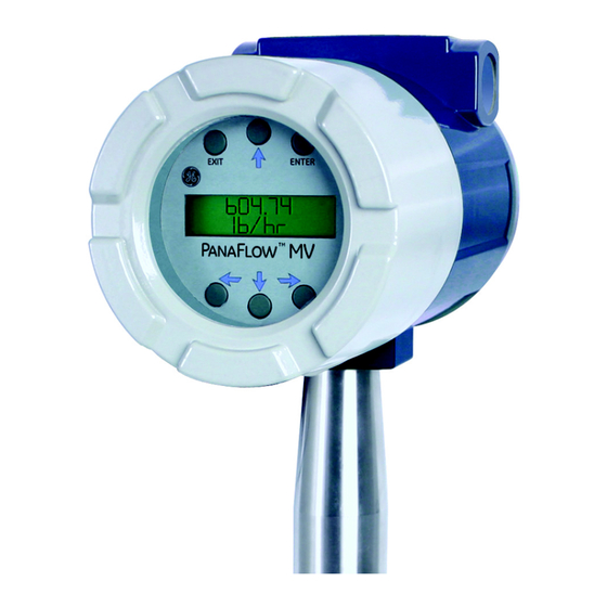
- Page 1 Measurement & Control Flow PanaFlow™ MV80 & MV82 Vortex Volumetric and Mass Flowmeters User’s Manual 910-292 Rev. C January 2016...
- Page 3 PanaFlow™ MV80 & MV82 Vortex Volumetric and Mass Flowmeters User’s Manual 910-292 Rev. C January 2016 www.gemeasurement.com ©2016 General Electric Company. All rights reserved. Technical content subject to change without notice.
- Page 4 Some models can only be properly cleaned during the manufacturing process. GE Measurement & Control is not liable for any damage or personal injury, whatsoever, resulting from the use of the MV80 or MV 82 standard mass flow...
- Page 5 Preface Information Paragraphs Note: These paragraphs provide information that provides a deeper understanding of the situation, but is not essential to the proper completion of the instructions. These paragraphs provide information that emphasizes instructions that are essential to proper setup of IMPORTANT: the equipment.
- Page 6 Environmental Compliance Waste Electrical and Electronic Equipment (WEEE) Directive GE Measurement & Control is an active participant in Europe’s Waste Electrical and Electronic Equipment (WEEE) take-back initiative, directive 2012/19/EU. The equipment that you bought has required the extraction and use of natural resources for its production. It may contain hazardous substances that could impact health and the environment.
-
Page 7: Table Of Contents
Contents Chapter 1. Introduction 1.1 Multi-Parameter Vortex Mass Flowmeters ............. . . 1 1.1.1 Multi-Parameter Mass Flowmeters . - Page 8 Contents 2.4 Adjusting the Meter Orientation ............... .29 2.4.1 Display/Keypad Adjustment (All Meters) .
- Page 9 Contents 3.3 Using the Setup Menus ................54 3.3.1 A Menu Map .
- Page 10 Contents 4.2.6i Control Register Definitions ..............90 4.2.6j Error Responses.
- Page 11 Contents Appendix A. Product Specifications Appendix B. Approvals Appendix C. Flowmeter Calculations C.1 In-Line Flowmeter Calculations ..............137 C.1.1 Volume Flow Rate .
- Page 12 Contents [no content intended for this page] PanaFlow™ MV80 & MV82 User’s Manual...
-
Page 13: Chapter 1. Introduction
MODBUS, BACNET or HART communications are also available. PanaFlow digital electronics allows for easy reconfiguration for most gases, liquids and steam. The PanaFlow MV80 & MV82 Meters' simple installation combines with an easy-to-use interface that provides quick set up, long term reliability and accurate mass flow measurement over a wide range of flows, pressures and temperatures. -
Page 14: How The Panaflow Vortex Mass Flowmeter Operates
1.2 How the PanaFlow Vortex Mass Flowmeter Operates PanaFlow MV80 and MV82 Mass Flowmeters (see Figure 1 below) use a unique sensor head to monitor mass flow rate by directly measuring three variables-fluid velocity, temperature and pressure. The built-in flow computer calculates the mass flow rate and volumetric flow rate based on these three direct measurements. -
Page 15: Vortex Shedding Frequency
Chapter 1. Introduction 1.3.1 Vortex Shedding Frequency Von Karman vortices form downstream of a shedder bar into two distinct wakes. The vortices of one wake rotate clockwise while those of the other wake rotate counterclockwise. Vortices generate one at a time, alternating from the left side to the right side of the shedder bar. -
Page 16: Flow Velocity Range
Chapter 1. Introduction 1.3.3 Flow Velocity Range To ensure trouble-free operation, vortex flowmeters must be correctly sized so that the flow velocity range through the meter lies within the measurable velocity range (with acceptable pressure drop) and the linear range. The measurable range is defined by the minimum and maximum velocity using Table 1 below. -
Page 17: Temperature Measurement
Chapter 1. Introduction 1.3.3 Flow Velocity Range (cont.) As shown in Figure 3 below, PanaFlow meters exhibit a constant Strouhal number across a large range of Reynolds numbers, indicating a consistent linear output over a wide range of flows and fluid types. Below this linear range, the intelligent electronics in PanaFlow automatically corrects for the variation in the Strouhal number with the Reynolds number. -
Page 18: Flowmeter Configurations
The output signal of insertion meters is the total flow rate in the channel. The accuracy of the total flow rate computation depends on adherence to the piping installation requirements given in Chapter 2. If adherence to those guidelines cannot be met, contact GE for specific installation advice. 1.6.1 Multivariable Options The MV80 or MV82 models are available with the following options: •... -
Page 19: Line Size, Process Connections And Materials
Chapter 1. Introduction 1.6.2 Line Size, Process Connections and Materials The MV80 In-line model is built for line sizes ½ through 4 inch wafer or ½ through 8 inch flanged design using ANSI 150, 300, 600, PN16, 40, or 64 class flanges. The MV82 Insertion model can be used in line sizes 2 inch and greater and is built with a compression fitting or packing gland design using 2 inch NPT, or 2 inch flanged connections (ANSI 150, 300, 600, PN16, 40, or 64 class flanges). - Page 20 Chapter 1. Introduction [no content intended for this page] PanaFlow™ MV80 & MV82 User’s Manual...
-
Page 21: Chapter 2. Installation
Chapter 2. Installation Chapter 2. Installation 2.1 Installation Overview PanaFlow Vortex Flowmeter installations are simple and straightforward. Both the Series MV80 In-Line and Series MV82 Insertion type flowmeter installations are covered in this chapter. After reviewing the installation requirements given below, see page 11 for Series MV80 installation instructions. See “Series MV82 Insertion Flowmeter Installation”... -
Page 22: Unobstructed Flow Requirements
Chapter 2. Installation 2.1.2 Unobstructed Flow Requirements Select an installation site that will minimize possible distortion in the flow profile. Valves, elbows, control valves and other piping components may cause flow disturbances. Check your specific piping condition against the examples shown in Figure 4 below. -
Page 23: Series Mv80 In-Line Flowmeter Installation
1.939" (2" schedule 80). Do not install the meter in a pipe with an inside diameter smaller than the inside diameter of the meter. For schedule 160 and higher pipe, a special meter is required. Consult GE before purchasing the meter. -
Page 24: Installing Wafer-Style Flowmeters
Chapter 2. Installation 2.2.2 Installing Wafer-Style Flowmeters Install the wafer-style meter between two conventional pipe flanges of the same nominal size as the flowmeter (see Figure 6 below). If the process fluid is a liquid, make sure the meter is located where the pipe is always full. This may require locating the meter at a low point in the piping system. - Page 25 Chapter 2. Installation 2.2.2 Installing Wafer-Style Flowmeters (cont.) To install the meter, complete the following steps: 1. Turn off the flow of process gas, liquid or steam. Verify that the line is not pressurized. Confirm that the installation site meets the required minimum upstream and downstream pipe diameters. 2.
-
Page 26: Installing Flange-Style Flowmeters
Chapter 2. Installation 2.2.3 Installing Flange-Style Flowmeters Install the flange-style meter between two conventional pipe flanges of the same nominal size as the flowmeter (see Figure 7 below). If the process fluid is a liquid, make sure the meter is located where the pipe is always full. This may require locating the meter at a low point in the piping system. -
Page 27: Series Mv82 Insertion Flowmeter Installation
Chapter 2. Installation 2.2.3 Installing Flange-Style Flowmeters (cont.) To install the meter, complete the following steps: 1. Turn off the flow of process gas, liquid or steam. Verify that the line is not pressurized. Confirm that the installation site meets the required minimum upstream and downstream pipe diameters. 2. -
Page 28: Cold Tap Guidelines
Chapter 2. Installation 2.3.1c Cold Tap Guidelines Refer to a standard code for all pipe tapping operations. The following tapping instructions are general in nature and intended for guideline purposes only. Proceed as follows: When using toxic or corrosive gases, purge the line with inert gas for a minimum of four CAUTION! hours at full gas flow before installing the flowmeter. -
Page 29: Hot Tap Guidelines
Chapter 2. Installation 2.3.1d Hot Tap Guidelines Hot tapping must be performed by a trained professional. US. regulations often require WARNING! a hot tap permit. The manufacturer of the hot tap equipment and/or the contractor performing the hot tap is responsible for providing proof of such a permit. All flowmeter connections, isolation valves, and fittings for hot tapping must have the WARNING! same pressure rating as the main pipeline or higher. - Page 30 Chapter 2. Installation 2.3.1d Hot Tap Guidelines (cont.) Proceed as follows: 1. Confirm that the installation site meets the minimum upstream and downstream pipe diameter requirements. 2. Weld a two inch mounting adapter on the pipe. Make sure the mounting adapter is within ± 5° perpendicular to the pipe centerline (see Figure 9 on page 16).
-
Page 31: Insertion Guidelines
Chapter 2. Installation 2.3.1e Insertion Guidelines The sensor head must be properly positioned in the pipe. For this reason, it is important that insertion length calculations are carefully followed. A sensor probe inserted at the wrong depth in the pipe will result in inaccurate readings. -
Page 32: Installing Flowmeters With A Compression Connection
Chapter 2. Installation 2.3.2 Installing Flowmeters with a Compression Connection Refer to Figure 11 below, and use the formula shown to determine insertion length for flowmeters (NPT and flanged) with a compression process connection. Flow Flow Insertion Length Formula Where: I = S –... - Page 33 Chapter 2. Installation 2.3.2 Installing Flowmeters with a Compression Connection (cont.) Example: To install a Series MV82 meter with a standard probe (S = 29.47 inches) into a 14 inch schedule 40 pipe, the following measurements (in inches) are taken: •...
- Page 34 Chapter 2. Installation 2.3.2 Installing Flowmeters with a Compression Connection (cont.) The sensor alignment pointer must point downstream, in the direction of flow. CAUTION! To avoid serious injury, DO NOT loosen the compression fitting under pressure. WARNING! Refer to Figure 12 on page 21 and complete the following steps: 1.
-
Page 35: Installing Flowmeters With A Packing Gland Connection
Chapter 2. Installation 2.3.3 Installing Flowmeters with a Packing Gland Connection Use the formula in Figure 13 below to determine the insertion depth for flowmeters (NPT and flanged) equipped with an insertion tool. To install, see “Insertion Procedure for Flowmeters with Permanent Insertion Tool” on page 24 for instructions for meters with a permanent insertion tool. -
Page 36: Insertion Procedure For Flowmeters With Permanent Insertion Tool
Chapter 2. Installation 2.3.3 Installing Flowmeters with a Packing Gland Connection (cont.) Example 2 - NPT Style Meters: In this example, the length of thread engagement on the NPT style meters must also subtracted in the equation shown in Figure 13 on page 23. The length of the threaded portion of the NPT meter is 1.18 inches. Measure the threaded portion still visible after the installation and subtract that amount from 1.18 inches. - Page 37 Chapter 2. Installation 2.3.4 Insertion Procedure for Flowmeters with Permanent Insertion Tool (cont.) The sensor alignment pointer must point downstream, in the direction of flow. CAUTION! Note: If line pressure is above 500 psig, it could require up to 25 ft-lb of torque to insert the flowmeter. Do not confuse this with possible interference in the pipe.
-
Page 38: Insertion Procedure For Flowmeters With Removable Insertion Tool
Chapter 2. Installation 2.3.5 Insertion Procedure for Flowmeters with Removable Insertion Tool Refer to Figure 15 below, and follow the instructions on the next page. Upper Retractor Bracket Depth Marker Arrow Stanchion Stem Lock Bolt (center) Scribe Mark Sensor Alignment Pointer Stem Stem Clamp Nuts... - Page 39 Chapter 2. Installation 2.3.5 Insertion Procedure for Flowmeters with Removable Insertion Tool (cont.) The sensor alignment pointer must point downstream, in the direction of flow. CAUTION! Note: If line pressure is above 500 psig, it could require up to 25 ft-lb of torque to insert the flowmeter. Do not confuse this with possible interference in the pipe.
-
Page 40: Installing Flowmeters With A Packing Gland Connection (No Insertion Tool)
Chapter 2. Installation 2.3.6 Installing Flowmeters with a Packing Gland Connection (No Insertion Tool) Use the formula in Figure 16 below to determine the insertion depth for meters with a packing gland connection (NPT and flanged) without an insertion tool. Insertion Length Formula I = S –... -
Page 41: Adjusting The Meter Orientation
Chapter 2. Installation 2.3.6 Installing Flowmeters with a Packing Gland Connection (No Insertion Tool) (cont.) The line pressure must be less than 50 psig for installation. WARNING! To install the meter, complete the following steps: 1. Calculate the required sensor probe insertion length. 2. -
Page 42: Display/Keypad Adjustment (All Meters)
Chapter 2. Installation 2.4.1 Display/Keypad Adjustment (All Meters) To adjust the display/keypad position, refer to Figure 17 below and complete the following steps: Rotate display/keypad in 90° increments (maximum 180° from original position). Figure 17: Display/Keypad Viewing Adjustment The electronics boards are electrostatically sensitive. Wear a grounding wrist strap and CAUTION! make sure to observe proper handling precautions required for static-sensitive components. -
Page 43: Enclosure Adjustment (Series Mv80 Only)
Chapter 2. Installation 2.4.2 Enclosure Adjustment (Series MV80 Only) To adjust the enclosure position, refer to Figure 18 below and complete the following steps: Loosen three setscrews and rotate enclosure (maximum 180° from original position) Figure 18: Enclosure Viewing Adjustment To avoid damage to the sensor wires, do not rotate the enclosure beyond 180°... -
Page 44: Loop Power Flowmeter Wiring Connections
Chapter 2. Installation 2.5 Loop Power Flowmeter Wiring Connections To avoid potential electric shock, follow National Electric Code safety practices or your WARNING! local code when wiring this unit to a power source and to peripheral devices. Failure to do so could result in injury or death. -
Page 45: Dc Input Power Connections
Chapter 2. Installation 2.5.1 DC Input Power Connections To access the wiring terminal blocks, locate and loosen the small set screw which locks the small enclosure cover in place. Then, unscrew the cover to expose the terminal block. Connect 4-20 mA loop power (12 to 36 VDC at 25 mA, 1W max.) to the terminals on the terminal +PWR -PWR... -
Page 46: Pulse Output Connections
Chapter 2. Installation 2.5.3 Pulse Output Connections The pulse output is used for a remote counter. When the preset volume or mass, as defined in the totalizer settings (see “The Totalizer #1 Menu” on page 60) has passed through the meter, the output provides a 50 millisecond square pulse. The pulse output requires a separate 5 to 36 VDC power supply connected to the normally-open, single-pole pulse output optical relay (see Figure 22 or Figure 23 below). -
Page 47: Frequency Output Connections
Chapter 2. Installation 2.5.4 Frequency Output Connections The frequency output is used for a remote counter. It can be scaled to output a 1 to 10 kHz signal proportional to mass or volume flow, temperature, pressure or density. The frequency output requires a separate 5 to 36 VDC power supply (see Figure 24 or Figure 25 below). In addition, there are current and power specifications that must be observed. -
Page 48: Remote Electronics Wiring
Chapter 2. Installation 2.5.6 Remote Electronics Wiring The remote electronics enclosure should be mounted in a convenient, easy-to-reach location. For hazardous location installations, make sure to observe agency requirements for installation. Allow some slack in the interface cable between the junction box and the remote electronics enclosure. To prevent damage to the wiring connections, do not put stress on the wiring connections at any time. -
Page 49: Line Power Meter Wiring Connections
Chapter 2. Installation 2.6 Line Power Meter Wiring Connections To avoid potential electric shock, follow National Electric Code safety practices or your WARNING! local code when wiring this unit to a power source and to peripheral devices. Failure to do so could result in injury or death. -
Page 50: Input Power Connections
Chapter 2. Installation 2.6.1 Input Power Connections To access the wiring terminal blocks, locate and loosen the small set screw which locks the small enclosure cover in place. Unscrew the cover to expose the terminal block. 2.6.1a AC Power Wiring The AC wire insulation temperature rating must meet or exceed 85°C (185°F). -
Page 51: Ma Output Connections
Chapter 2. Installation 2.6.2 4-20 mA Output Connections The standard PanaFlow meter has a single 4-20 mA loop. Two additional loops are available on the optional communication board. The 4-20 mA loop current is controlled by the meter electronics. The electronics must be wired in series with the sensor resistor or current meter (see Figure 31, Figure 32 or Figure 33 below). -
Page 52: Frequency Output Connections
Chapter 2. Installation 2.6.2 4-20 mA Output Connections (cont.) The maximum loop resistance (load) for the current loop output is dependent upon the supply voltage and is given in Figure 34 below. The 4-20 mA loop is optically isolated from the flowmeter electronics. is the total resistance in the loop, including the wiring resistance. - Page 53 Chapter 2. Installation 2.6.3 Frequency Output Connections (cont.) AC or DC powered meters R current limit Freq Out + Freq. Out voltage = +V Select resistor so that current Freq Out – through Freq. Out < 40mA R current limit Figure 35: Isolated Frequency Output Using External Power Supply R current limit ~10K DC Power...
-
Page 54: Pulse Output Connections
Chapter 2. Installation 2.6.4 Pulse Output Connections The pulse output is used for a remote counter. When the preset volume or mass, as defined in the totalizer settings (see “The Totalizer #1 Menu” on page 60) has passed through the meter, the output provides a 50 millisecond square pulse. The pulse output is a normally-open, single-pole pulse output optical relay with a nominal 200 volt/160 ohm rating (i.e., it has a nominal on-resistance of 160 ohms, and the largest voltage it can withstand across the output terminals is 200 volts). - Page 55 Chapter 2. Installation 2.6.4 Pulse Output Connections (cont.) AC or DC powered meters R current limit Pulse + Pulse voltage = +V Select resistor so that current Pulse – through pulse < 40mA R current limit Figure 38: Isolated Pulse Output with External Power Supply R current limit ~10K DC Power + Pwr...
-
Page 56: Alarm Output Connections
Chapter 2. Installation 2.6.5 Alarm Output Connections One alarm output ( ) is included on the standard PanaFlow meter. Two or more alarms ( ) are Alarm 1 Alarm 2 Alarm 3 included on the optional communication board. The alarm output is used for transmitting high or low process conditions, as defined in the alarm settings (see “The Alarms Menu”... - Page 57 Chapter 2. Installation 2.6.5 Alarm Output Connections (cont.) AC or DC powered meters R current limit Alarm + Pulse voltage = +V Select resistor so that current Alarm – through pulse < 40mA R current limit Figure 41: Isolated Alarm Output with External Power Supply R current limit ~10K DC Power + Pwr...
-
Page 58: Remote Electronics Wiring
Chapter 2. Installation 2.6.6 Remote Electronics Wiring The remote electronics enclosure should be mounted in a convenient, easy to reach location. For hazardous location installations, make sure to observe agency requirements for installation. Allow some slack in the interface cable between the junction box and the remote electronics enclosure. -
Page 59: Optional Input Wiring
Chapter 2. Installation 2.6.7 Optional Input Wiring The meter has two optional input wiring terminals. These can be used to input a Remote or Second RTD input in situations such as: an Energy Monitoring meter, the input of a Remote Pressure Transducer, to pass a Contact Closure, for a Remote Density measurement, etc. -
Page 60: Optional External 4-20 Ma Input Wiring
Chapter 2. Installation 2.6.7b Optional External 4-20 mA Input Wiring The meter is set to have Option 1 used for the external input. Programming menus that pertain to the optional 4-20 mA input are located in “Hidden Diagnostics Menus” on page 109. Refer to Figure 47 below to wire the external 4-20 mA input into the flowmeter using an external power supply. -
Page 61: Optional Contact Closure Input Wiring
Chapter 2. Installation 2.6.7b Optional External 4-20 mA Input Wiring (cont.) Refer to Figure 49 below to wire the external 4-20 mA input into the flowmeter using power from the 24 VDC output of an AC powered meter. Option 1 Option 2 AC units only. - Page 62 Chapter 2. Installation [no content intended for this page] PanaFlow™ MV80 & MV82 User’s Manual...
-
Page 63: Chapter 3. Operating Instructions
Chapter 3. Operating Instructions Chapter 3. Operating Instructions After installing the PanaFlow Vortex Flowmeter per the instructions in the previous chapter, you are ready to begin operation. The sections in this chapter explain the display/keypad commands and meter start-up and programming. The meter is ready to operate at start up without any special programming. - Page 64 Chapter 3. Operating Instructions Flowmeter Display/Keypad (cont.) Figure 52 below shows a picture of the display/keypad. From Run Mode, the ENTER key enables access to the Setup Menus through a password screen. Within the Setup Menus, pressing ENTER activates the current field. To set new parameters, press the ENTER key until an underline cursor appears.
-
Page 65: Start-Up
Chapter 3. Operating Instructions 3.2 Start-Up To begin flowmeter operation: 1. Verify that the flowmeter is installed and wired as described in Chapter 2. 2. Apply power to the meter. At start up, the unit runs a series of self-tests that check the RAM, ROM, EPROM and all flow sensing components. -
Page 66: Using The Setup Menus
Chapter 3. Operating Instructions 3.3 Using the Setup Menus 3.3.1 A Menu Map Figure 54: Complete Map of Setup Menus PanaFlow™ MV80 & MV82 User’s Manual... -
Page 67: Programming The Flowmeter
Chapter 3. Operating Instructions 3.3.2 Programming the Flowmeter 1. Enter the Setup Menu by pressing the ENTER key until prompted for a password. Note: All outputs are disabled while using the Setup Menus. 2. Use the keys to select the new password characters ( is the factory-set password). - Page 68 Chapter 3. Operating Instructions 3.3.3 The Output Menu (cont.) ENTER Run Mode Password ENTER Output Menu keys to access menus <Measure> None 4-20mA Output 1 Mass < 4mA = xxxx > < 20mA = xxxx > More > Volume xxxx xxxx xxxx ***see...
-
Page 69: The Display Menu
Chapter 3. Operating Instructions 3.3.4 The Display Menu Use the Display Menu shown in Figure 56 below to set the cycle time for automatic screen sequencing used in Run Mode, change the precision of displayed values, smooth the values or enable or disable each item displayed in the Run Mode screens. -
Page 70: The Alarms Menu
Chapter 3. Operating Instructions 3.3.5 The Alarms Menu As an example of how to set an output, refer to Figure 57 on page 59. This example shows how to set Relay Alarm 1 to activate if the mass flow rate is greater than 100 lb/hr. You can check the alarm configuration in Run Mode by pressing keys until Alarm [1] appears. - Page 71 Chapter 3. Operating Instructions 3.3.5 The Alarms Menu (cont.) ENTER Run Mode Password ENTER Alarms *see below Menu keys to access menus <Measure> None Mass < Mode > Relay Alarm 1 <Measure> units Volume None More > xxxx **Energy HIGH Alarm (>) LOW Alarm (<) Temp 1,2 Press...
-
Page 72: The Totalizer #1 Menu
Chapter 3. Operating Instructions 3.3.6 The Totalizer #1 Menu Use the Totalizer Menu to configure and monitor the totalizer. The totalizer output is a 50 millisecond (.05 second) positive pulse (relay closed for 50 milliseconds). The totalizer cannot operate faster than one pulse every 100 millisecond (.1 second). - Page 73 Chapter 3. Operating Instructions 3.3.6 The Totalizer #1 Menu (cont.) ENTER Run Mode Password ENTER Totalizer Menu keys to access menus Totaling Inactive Mass Example: Volume Energy Maximum flow rate = 600 gallons per minute (600 gallons per minute = 10 gallons per second). If unit per pulse is set to 600 gallons per pulse, (unit)/Pulse the totalizer will pulse once every minute.
-
Page 74: The Totalizer #2 Menu
Chapter 3. Operating Instructions 3.3.7 The Totalizer #2 Menu Refer to Figure 59 below, and use Totalizer #2 to Monitor Flow or Energy. Note: Totalizer #2 does not operate a relay - it is for monitoring only. ENTER Run Mode Password ENTER Totalizer... -
Page 75: The Energy Menu For Ems Energy Meters Only
Chapter 3. Operating Instructions 3.3.8 The Energy Menu for EMS Energy Meters Only There are several possibilities regarding the measurement of water or steam energy, given the location of the meter and the use of a second RTD. Table 3 below summarizes the possibilities: Table 3: Configuration Options Fluid Meter Location... - Page 76 Chapter 3. Operating Instructions 3.3.8 The Energy Menu for EMS Energy Meters Only (cont.) ENTER Run Mode Password ENTER Energy Menu keys to access menus Loc in Sent Flow Yes or No Heating System Yes or No % Returned Figure 60: The Energy Menu for EMS Energy Meters Only PanaFlow™...
-
Page 77: The Fluid Menu
Chapter 3. Operating Instructions 3.3.9 The Fluid Menu Use the Fluid Menu (see Figure 61 on page 66) to configure the flowmeter for use with common gases, liquids and steam. Your flowmeter is pre-programmed at the factory for your application's process fluid. Reference Richard W. - Page 78 Chapter 3. Operating Instructions 3.3.9 The Fluid Menu (cont.) Figure 61: The Fluid Menu PanaFlow™ MV80 & MV82 User’s Manual...
-
Page 79: The Units Menu
Chapter 3. Operating Instructions 3.3.10 The Units Menu Use the Units Menu (see Figure 62 below) to configure the flowmeter with the desired units of measurement. These are global settings and determine what appears on all screens. ENTER Run Mode Password ENTER Units... -
Page 80: The Time & Date Menu
Chapter 3. Operating Instructions 3.3.11 The Time & Date Menu Use the Time and Date Menu (see Figure 63 below) to enter the correct time and date into the flowmeter's memory. The parameters are used in the Run Mode and the alarm and system log files. Note: Time is displayed in AM/PM format, but military format is used to set the time. -
Page 81: The Diagnostics Menu
Chapter 3. Operating Instructions 3.3.12 The Diagnostics Menu Use the Diagnostics Menu (see Figure 64 on page 70) to simulate operation and review the system files. The system log files contain time/date stamped messages including: power on, power off, programming time outs, parameter faults, incorrect password entry and other various information relative to system operation and programming. - Page 82 Chapter 3. Operating Instructions 3.3.12 The Diagnostics Menu (cont.) ENTER Run Mode Password ENTER Diagnostics Menu keys to access menus Simulate Vortex Sim Vor Freq Frequency (Hz) *Simulate Temperature Sim Temp 1,2 *Simulate Pressure Sim Pressure For a V model in any fluid, enter nominal operating temperature and pressure as simulated values in the diagnostics menu.
-
Page 83: The Calibration Menu
The are set at the factory. Vortex Coef Ck Low Flow Cutoff Consult GE for help with these settings if the meter is showing erratic flow rate readings. ENTER Run Mode Password... -
Page 84: The Password Menu
Chapter 3. Operating Instructions 3.3.14 The Password Menu Use the Password Menu (see Figure 66 below) to set or change the system password. The factory-set password is 1234 ENTER Run Mode Password ENTER Password Menu keys to access menus Set Password 1234 Figure 66: The Password Menu PanaFlow™... -
Page 85: Chapter 4. Serial Communications
Chapter 4. Serial Communications Chapter 4. Serial Communications 4.1 HART Communications The HART Communications Protocol (Highway Addressable Remote Transducer Protocol) is a bidirectional digital serial communications protocol. The HART signal is based on the Bell 202 standard and is superimposed on the 4-20 mA Output 1. -
Page 86: Hart Dc Powered Meter Wiring
Chapter 4. Serial Communications 4.1.1b HART DC Powered Meter Wiring Vortex Meter R load, Current Power 250 ohm Meter Supply minimum Field Connection Remote Connection for Communicator for Communicator Figure 68: HART DC Powered Meter Wiring PanaFlow™ MV80 & MV82 User’s Manual... -
Page 87: Hart Ac Powered Meter Wiring
Chapter 4. Serial Communications 4.1.1c HART AC Powered Meter Wiring Vortex Meter R load, Current 250 ohm Meter minimum Field Connection Remote Connection for Communicator for Communicator Figure 69: HART AC Powered Meter Wiring PanaFlow™ MV80 & MV82 User’s Manual... -
Page 88: Hart Commands With The Digital Display Menu
Chapter 4. Serial Communications 4.1.2 HART Commands with the Digital Display Menu Online Menu 1 Device Setup 1 Display Unit 1 Mass Flo Unit 2 Vol Unit 3 Temp Unit 4 Energy Flo Unit 1 Norm Temp 5 Line Press Unit 2 Norm Press 6 Dens Unit 3 Std Temp... - Page 89 Chapter 4. Serial Communications 4.1.2 HART Commands with the Digital Display Menu (cont.) Analog Output Menu 1 Fix Analog Output 2 Trim Analog Output From Online Menu 1 PV is 3 Configure AO1 2 PV AO1 Out 4 PV is 3 PV 5 PV AO1 Out 4 PV % rnge...
- Page 90 Chapter 4. Serial Communications 4.1.2 HART Commands with the Digital Display Menu (cont.) Fluid Menu From Online Menu 1 Fluid Liquid Water 2 Fluid Type Other Liquid Ammonia Goyal-Dorais Chlorine API-2540 Nat Gas AGA8 Real Gas Other Liquid Density Other Gas Viscosity Coef AL Liquified Gas Viscosity Coef BL...
- Page 91 Chapter 4. Serial Communications 4.1.2 HART Commands with the Digital Display Menu (cont.) Diagnostics Menu 1 Vortex Diag 1 Vtx Freq From Online Menu 2 Press Diag 2 Sim Vtx Freq 3 Temp Diag 3 Vtx AtoD 4 Vel 4 Filter Set 5 Temp 5 Gain Set 6 Temp 2...
- Page 92 Chapter 4. Serial Communications 4.1.2 HART Commands with the Digital Display Menu (cont.) Sensor Cal Menu To Calibration Review Menu 1 Calibration Review From Online Menu 1 Vol snsr unit 1 Vtx Freq 2 Vortex Sensor 2 USL 2 Sim Vtx Freq 3 Vortex Cal 3 LSL 3 Vtx AtoD...
-
Page 93: Hart Commands With The Generic Digital Display Menu
Chapter 4. Serial Communications 4.1.3 HART Commands with the Generic Digital Display Menu Note: Use password 16363. Online Menu 1 Device Setup 1 Snsr 1 4 mA 2 PV 2 AI % Rnge 2 20 mA 3 PV AO 3 AO1 3 Other 1 4 mA 4 End... -
Page 94: Fast Key Sequence
Chapter 4. Serial Communications 4.1.4 Fast Key Sequence Note: Use password 16363. Table 4: Fast Key Sequence Sequence Description Access Notes 1,1,1 Snsr View Primary variable value 1,1,2 AI % Rnge View Analog output % range 1,1,3 View Analog output, mA 1,2,1 Test Device Not used... - Page 95 Chapter 4. Serial Communications Table 4: Fast Key Sequence (cont.) Sequence Description Access Notes 1,4,1,2 PV Sensor Unit Edit Primary variable units 1,4,1,3 Sensor Information View PV LSL, PV USL, PV Min span 1,4,2,1 Snsr Damp Edit Primary variable damping (time constant) in seconds 1,4,2,2,1 PV LRV Edit...
-
Page 96: Modbus Communications
Chapter 4. Serial Communications 4.2 Modbus Communications Place the controls in manual mode when making configuration changes to the vortex WARNING! meter. 4.2.1 Applicable Flowmeter Models PanaFlow Mass Flowmeters, Models MV80 and MV82 with Modbus communication protocol and firmware version 4.00.58 and above are capable of Modbus commuinications. -
Page 97: Wiring
Chapter 4. Serial Communications 4.2.4 Wiring An RS485 daisy chained network configuration, as shown in Figure 76 below, is recommended. Do not use a star, ring, or cluster arrangement. RS-485 Master RS-485 – RS-485 + RS-485 GND Other Device 1 Vortex Meter Other Device 2, etc. -
Page 98: Menu Items
Chapter 4. Serial Communications 4.2.6 Menu Items The following menu items are in the Output Menu and allow selection and control of the Modbus communication protocol. 4.2.6a Address When the Modbus protocol is selected, the Modbus address is equal to the user programmable device address if it is in the range 1…247, in accordance with the Modbus specification. -
Page 99: Modbus Protocol
Chapter 4. Serial Communications 4.2.6e Modbus Protocol The Modbus RTU protocol is supported in this implementation. Supported baud rates are 1200, 2400, 4800, 9600, 19200, 38400, 57600, and 115200. The default baud rate is 19200 baud. Depending upon the Modbus protocol selected, data is transmitted in 8-bit data frames with even or odd parity and 1 stop bit, or no parity and 2 or 1 (non-standard) stop bits. -
Page 100: Register Definitions
Chapter 4. Serial Communications 4.2.6f Register Definitions The meter serial number and those variables that are commonly monitored (mass, volume and energy flow rates, total, pressure, temperature, density, viscosity, Reynolds number, and diagnostic variables such as frequency, velocity, gain, amplitude and filter setting) are accessible via the Modbus protocol. Long integer and floating point numbers are accessed as pairs of 16-bit registers in the register order selected in the Modbus Order menu. - Page 101 Chapter 4. Serial Communications 4.2.6f Register Definitions (cont.) Table 9 below shows the registers that are available with the energy meter firmware. Table 9: Energy Firmware Registers Registers Variable Data Type Units Function Code Addresses 30527-30528 Totalizer #2 unsigned long display units* 03, 04 526-527...
-
Page 102: Exception Status Definitions
Chapter 4. Serial Communications 4.2.6g Exception Status Definitions The Read Exception Status command (function code 07) returns the exception status byte, which is defined as shown in Table 11 below. This byte may be cleared by setting “coil” register #00003 (function code 5, address 2, data = 0xff00). Table 11: Exception Status BIts Bit(s) Definition... -
Page 103: Error Responses
Chapter 4. Serial Communications 4.2.6j Error Responses If an error is detected in the message received by the unit, the function code in the response is the received function code with the most significant bit set, and the data field will contain the exception code byte (see Table 13 below). Table 13: Exception Codes Exception Code Description... -
Page 104: Examples
Chapter 4. Serial Communications 4.2.6n Examples Read the exception status byte from the device with address 1: 01 07 41 E2 01 Device address 07 Function code 04 = read exception status A typical response from the device is as follows: 01 07 03 62 31 01 Device address 07 Function code... - Page 105 Chapter 4. Serial Communications 4.2.6n Examples (cont.) An attempt to read register(s) that don't exist: 01 04 00 00 00 50 F1 D2 01 Device address 04 Function code 4 = read input register 00 00 Starting address 00 50 Number of registers = 80 F0 36 CRC This results in an error response as follows: 01 84 02 C2 C1...
- Page 106 Chapter 4. Serial Communications 4.2.6n Examples (cont.) To reset the totalizer: 01 05 00 00 FF 00 8C 3A 01 Device address 05 Function code 5 = write single coil 00 09 Coil address = 9 FF 00 Data to reset totalizer 8C 3A CRC (not the correct CRC EJS-02-06-07) The unit responds with an identical message to that transmitted, and the totalizer is reset.
-
Page 107: Bacnet Ms/Tp Communications
Chapter 4. Serial Communications 4.3 BACnet MS/TP Communications 4.3.1 BACnet MS/TP Description The BACnet Master-Slave/Token-Passing (MSTP) driver implements a data link protocol that uses the services of the RS-485 physical layer. The MS/TP bus is based on BACnet standard protocol SSPC-135, Clause 9. BACnet MS/TP protocol is a peer-to-peer, multiple master protocols based on token passing. -
Page 108: Supported Bacnet Objects
Chapter 4. Serial Communications 4.3.4 Supported BACnet Objects A BACnet object represents physical or virtual equipment information, as a digital input or parameters. The MV 80 and MV 82 Vortex Mass Flow Meters present the following object types: a. Device Object b. - Page 109 Chapter 4. Serial Communications Table 17: Properties Object Types (cont.) Object Types Properties Device Analog Input Binary Input Binary Value Status_Flags Event_State Reliability Out_Of_Service (W) (W) (W) Units Polarity (W) Priority_Array Relinquish_Default Status_Flag ...
-
Page 110: Device Object
The Device object default property values are listed in Table 18 below. Table 18: Properties Default Values Properties Default Values object-identifier object-name Device,1 object-type Device system-status operational vendor-name GE Measurement & Control vendor-identifier model-name Multivariable Flowmeter firmware-revision application-software-version 1.07 protocol-version protocol-revision protocol-services-supported {F,F,F,F,F,F,F,F,F,F,F,F,T,F,T,T,T,T,F,F,F,F,F,F,F,F,F,F,F,F,T,T,F,F,F,F,F} protocol-object-types-supported... -
Page 111: Analog Input Object
Chapter 4. Serial Communications 4.3.4b Analog Input Object MV 80 and MV 82 Vortex Mass Flow Meters Analog Input type objects are described in table below. Table 19: Analog Input Object Types Object Instance Object Name Unit Description Volume Flow cubic-feet-per-second, This AI object is used to measure volume flow. - Page 112 Chapter 4. Serial Communications Table 19: Analog Input Object Types (cont.) Object Instance Object Name Unit Description Totalizer 1 and If Totalizer selection for Mass An electronic counter which records the total Totalizer 2 measure – accumulated flow over a certain range of time. pounds-mass-per-second, grams-per-second, kilograms-per-second,...
-
Page 113: Binary Input Objects
Chapter 4. Serial Communications 4.3.4c Binary Input Objects The MV 80 and MV82 Vortex Mass Flow Meters Binary Input type objects are described in Table 20 below. Table 20: Binary Input Object Types Object Object Instance Name Description Alarm1 The status of the three alarms may be monitored via the Modbus command. -
Page 114: Annex - Bacnet Protocol Implementation Conformance Statement
Chapter 4. Serial Communications 4.3.5 ANNEX - BACnet Protocol Implementation Conformance Statement Date: 19-April-2012 Vendor Name: VorTek Instruments Product Name: Pro-V M22 multivariable flow-meter Product Model Number: M22/M23 VT/VTP Applications Software Version: 1.07 Firmware Revision: N/A BACnet Protocol Revision: 4 Product Description: VorTek multivariable flow-meter BACnet Standardized Device Profile (Annex L): ... - Page 115 Chapter 4. Serial Communications 4.3.5 ANNEX - BACnet Protocol Implementation Conformance Statement (cont.) Table 23: Services Supported Read Property Execute Write Property Execute Read Property Multiple Execute Write Property Multiple Execute Who-Is Execute I-Am Initiate Who-Has Execute I-Have Initiate Device Communication Control Execute Segmentation Capability: ...
- Page 116 Chapter 4. Serial Communications 4.3.5 ANNEX - BACnet Protocol Implementation Conformance Statement (cont.) Object List: Table 26: Properties of Analog Input/Value Object Types Name Present Value Status Flags Event State Out of Service Units Volume Flow F,F,F,F Normal False Mass Flow F,F,F,F Normal False...
- Page 117 Chapter 4. Serial Communications 4.3.5 ANNEX - BACnet Protocol Implementation Conformance Statement (cont.) Data Link Layer Options: BACnet IP, (Annex J) BACnet IP, (Annex J), Foreign Device ISO 8802-3, Ethernet (Clause 7) ANSI/ATA 878.1, 2.5 Mb. ARCNET (Clause 8) ANSI/ATA 878.1, EIA-485 ARCNET (Clause 8), baud rate(s) MS/TP master (Clause 9), baud rate(s): 9600, 19200, 38400 MS/TP slave (Clause 9), baud rate(s): Point-To-Point, EIA 232 (Clause 10), baud rate(s):...
- Page 118 Chapter 4. Serial Communications 4.3.5 ANNEX - BACnet Protocol Implementation Conformance Statement (cont.) Character Sets Supported: Indicating support for multiple character sets does not imply that they can all be supported simultaneously. ANSI X3.4 IBM™/Microsoft™DBCS ISO 8859-1 ISO 10646 (UCS-2) ISO 10646 (UCS-4) JIS C 6226 If this product is a communication gateway, describe the types of non-BACnet equipment/network(s)
-
Page 119: Acronyms And Definitions
Chapter 4. Serial Communications 4.3.6 Acronyms and Definitions Table 27: Acronym Definitions Acronym Definition APDU Application Protocol Data Unit BACnet Building Automation and Control Network- Data communication protocol MS/TP Master-Slave Token passing (a twisted pair RS485 network created by BACnet) BIBB BACnet Interoperability Building Block (Specific individual function blocks for data exchange between interoperable devices). - Page 120 Chapter 4. Serial Communications [no content intended for this page] PanaFlow™ MV80 & MV82 User’s Manual...
-
Page 121: Chapter 5. Troubleshooting And Repair
Chapter 5. Troubleshooting and Repair Chapter 5. Troubleshooting and Repair Before attempting any flowmeter repair, verify that the line is not pressurized. Always WARNING! remove the main power before disassembling any part of the mass flowmeter. 5.1 Hidden Diagnostics Menus The menus shown in Figure 77 on page 110 can be accessed using the password 16363 and then completing the... - Page 122 Chapter 5. Troubleshooting and Repair Hidden Diagnostics Menus (cont.) (--------- Level One Values ---------) (---------------------- Level Two Values ----------------------) Output Type xxxx None xxxxxxxxxx xxxx Mode xxxx 2700 Sig. Rev Reynolds Micro Rev xxxx Correction 0.0003 Rtd1 = x.x Gain Press 9 C's Rtd2 = x.x xxxx...
-
Page 123: Level One Hidden Diagnostics Values
Chapter 5. Troubleshooting and Repair 5.1.1 Level One Hidden Diagnostics Values • = Vortex shedding frequency (Hz). • = Adaptive filter - should be about 25% higher than the vortex shedding frequency, this is a low-pass filter. If the meter is using the Filter Control (see below) in manual mode, will be displayed as •... - Page 124 Chapter 5. Troubleshooting and Repair 5.1.1 Level One Hidden Diagnostics Values (cont.) • = Calculated at current operating conditions. is a variable in the equation that relates signal strength, density, and velocity for a given application. It is used for noise rejection purposes. directly controls the value (see above).
-
Page 125: Column Two Hidden Diagnostics Values
Chapter 5. Troubleshooting and Repair 5.1.2 Column Two Hidden Diagnostics Values • = Analog counts to calibrate zero on analog output 1. 4-20(1) Zero • = Analog counts to cal. full scale on analog output 1. 4-20(1) FScale • = Analog counts to calibrate zero on analog output 2. 4-20(2) Zero •... - Page 126 Chapter 5. Troubleshooting and Repair 5.1.2 Level Two Hidden Diagnostics Values (cont.) • = Filter setting - Factory use only High Pass Filter • = Reset factory defaults. If you change this to Yes and press ENTER, all the factory Factory Defaults configuration is lost and you must reconfigure the entire program.
-
Page 127: Analog Output Calibration
Chapter 5. Troubleshooting and Repair 5.1.2 Level Two Hidden Diagnostics Values (cont.) • Correction Pairs • ft3/sec (1 through 10) • (1 through 10) %Dev. • = Factory use only. Roughness • Force Recal? = Factory use only. • - Energy EMS meters only. Sets the deadband for totalization to begin. Must be greater than this Min. -
Page 128: Troubleshooting The Flowmeter
Chapter 5. Troubleshooting and Repair 5.3 Troubleshooting the Flowmeter Before attempting any flowmeter repair, verify that the line is not pressurized. Always WARNING! remove the main power before disassembling any part of the flowmeter. Use hazardous area precautions if applicable. Static sensitive electronics - use electrostatic discharge precautions. Check These Items: •... - Page 129 Chapter 5. Troubleshooting and Repair Troubleshooting the Flowmeter (cont.) Record These Values (cont.) Record the values listed in Table 29 below from the Hidden Diagnostics Menu with the meter installed: (Use the password to access the Hidden Diagnostics Menu). 16363 Table 29: Hidden Diagnostics Menu Values Parameter With Flow...
-
Page 130: Determine The Fault
Chapter 5. Troubleshooting and Repair 5.4 Determine the Fault 5.4.1 Symptom: Output at No Flow • The low flow cutoff is set too low. At no flow, go to the first column of the hidden diagnostics menu and record value. The low flow cutoff must be set above this value. •... -
Page 131: Symptom: No Output
Chapter 5. Troubleshooting and Repair 5.4.3 Symptom: No Output 1. For remote mounted electronics, carefully check all the wiring connections in the remote mount junction box. There are 18 connections that must be correct, verify each color (black and red), shield, and wire number. 2. - Page 132 60 Hz for example. If all readings are correct, re-install the vortex sensor wires. 5. Verify all meter configuration and troubleshooting steps previously described. There are many possible causes of this problem. Consult GE if necessary. PanaFlow™ MV80 & MV82 User’s Manual...
-
Page 133: Symptom: Meter Displays Temperature Fault
(see Figure 81 below). It should read approximately 1080 ohms at room temperature (higher resistance at higher temperatures). OUTSIDE OUTSIDE Figure 81: Temperature Sensor Connector Pins 4. Consult GE with your findings PanaFlow™ MV80 & MV82 User’s Manual... -
Page 134: Symptom: Meter Displays Pressure Fault
(see Figure 82 below). Both readings should be approximately 4000 ohms. OUTSIDE INSIDE INSIDE OUTSIDE Figure 82: Pressure Sensor Connector 3. Go to the first column of the hidden diagnostics and record the values and consult GE with your Pe(V) Pv(V) findings. PanaFlow™ MV80 & MV82 User’s Manual... -
Page 135: Electronics Assembly Replacement (All Meters)
Chapter 5. Troubleshooting and Repair 5.5 Electronics Assembly Replacement (All Meters) The electronics boards are electrostatically sensitive. Wear a grounding wrist strap and CAUTION! make sure to observe proper handling precautions required for static-sensitive components. Before attempting any flowmeter repair, verify that the line is not pressurized. Always WARNING! remove the main power before disassembling any part of the mass flowmeter. -
Page 136: Pressure Sensor Replacement (Series Mv80 Only)
Before returning any PanaFlow MV flowmeter to the factory, you must request a Return Material Authorization ( number. To obtain an number and the correct shipping address, contact GE Customer Service using the information on the back cover of this manual. -
Page 137: Appendix A. Product Specifications
Appendix A. Product Specifications Appendix A. Product Specifications Accuracy MV80 Series In-Line Meters MV82 Series Insertion Meters Process Variables Liquids Gas & Steam Liquids Gas & Steam Mass ±1% of rate over ±1.5% of rate over ±1.5% of rate over ±2% of rate over Flow Rate... - Page 138 Typical mass flow ranges are given in the following table. Precise flow depends on the fluid and pipe size. MV82 insertion meters are used with pipe sizes from 2 inch and above. Consult GE for sizing assistance. Water Minimum and Maximum Flow Rates ½-inch...
- Page 139 Appendix A. Product Specifications Flow Rates (cont.) Typical Air (@20°F) Minimum and Maximum Flow Rates (nm /hr) Nominal Pipe Size (mm) Pressure 0 barg 1307 2275 5157 9034 5 barg 1339 2080 3476 7775 13533 30682 53749 10 barg 1035 1814 1554 3819...
- Page 140 Appendix A. Product Specifications Flow Rates (cont.) Typical Saturated Steam Minimum and Maximum Flow Rates (lb/hr) Nominal Pipe Size (in) Pressure 0.75 5 psig 1264 1087 2431 4231 9594 16806 100 psig 1652 2893 1386 3405 5690 12729 22156 50233 87998 200 psig 2229...
- Page 141 Appendix A. Product Specifications Linear Range Smart electronics corrects for lower flow down to a Reynolds number of 5,000. The Reynolds number is calculated using the fluid's actual temperature and pressure monitored by the meter. Rangeability depends on the fluid, process connections and pipe size.
- Page 142 Appendix A. Product Specifications Pressure Transducer Ranges Pressure Sensor Ranges , psia (bara) Full Scale Operating Pressure Maximum Over-Range Pressure psia bara psia bara 1000 1500 2500 To maximize accuracy, specify the lowest full scale operating pressure range for the application. To avoid damage, the flowmeter must never be subjected to pressure above the over-range pressure shown above.
- Page 143 Appendix A. Product Specifications Process Fluid and Ambient Temperature Process Fluid: Standard temperature sensor: –330 to 500°F (–200 to 260°C) High temperature sensor: to 750°F (400°C) Ambient: Operating temperature range: –40 to 140° F (–40 to 60° C) Storage temperature range: –40 to 185° F (–40 to 85° C) Maximum relative humidity: 0-98%, non-condensing conditions Maximum altitude: –2000 to 14,000 feet (–610 to 4268 meters) Pollution Degree 2 for the ambient environment...
- Page 144 Appendix A. Product Specifications Wetted Materials Series MV80 In-Line Flowmeter: 316L stainless steel standard C276 hastelloy or A105 carbon steel optional Series MV82 Insertion Flowmeter: 316L stainless steel standard. Teflon® packing gland below 500° F (260° C) Graphite packing gland above 500° F (260° C) Enclosure Protection Classification NEMA 4X and IP66 cast enclosure Electrical Ports...
- Page 145 Appendix A. Product Specifications Model Number Information —Series MV80 In-Line Flowmeter PanaFlow™ MV80 & MV82 User’s Manual...
- Page 146 Appendix A. Product Specifications Model Number Information: Series MV82 Insertion Flowmeter PanaFlow™ MV80 & MV82 User’s Manual...
-
Page 147: Appendix B. Approvals
Ex d IIB + H2 T6 Ex tD A21 IP66 T85°C IECEx KEM 08.0018 Technical assistance may be obtained by contacting GE Customer Service using the information on the back cover of this manual. PanaFlow™ MV80 & MV82 User’s Manual... - Page 148 Appendix B. Approvals [no content intended for this page] PanaFlow™ MV80 & MV82 User’s Manual...
-
Page 149: Appendix C. Flowmeter Calculations
Appendix C. Flowmeter Calculations Appendix C. Flowmeter Calculations C.1 In-Line Flowmeter Calculations C.1.1 Volume Flow Rate -- - C.1.2 Mass Flow Rate ρ C.1.3 Flowing Velocity ----- Where: A = Cross sectional area of the pipe (ft f = Vortex shedding frequency (pulses/sec) K = Meter factor corrected for thermal expansion (pulses/ft = Mass flow rate (lbm/sec) = Volume flow rate (ft... -
Page 150: Insertion Flowmeter Calculations
Appendix C. Flowmeter Calculations C.2 Insertion Flowmeter Calculations C.2.1 Flowing Velocity ---- - C.2.2 Volume Flow Rate C.2.3 Mass Flow Rate Aρ Where: A = Cross sectional area of the pipe (ft f = Vortex shedding frequency (pulses/sec) = Meter factor corrected for Reynolds Number (pulses/ft) = Volume flow rate (ft /sec) = Mass flow rate (lbm/sec) -
Page 151: Fluid Calculations
Appendix C. Flowmeter Calculations C.3 Fluid Calculations C.3.1 Calculations for Steam T & P When “Steam T & P” is selected in the “Real Gas” selection of the Fluid Menu, the calculations are based on the equations below. C.3.1a Density The density of steam is calculated from the formula given by Keenan and Keys. -
Page 152: C.3.1B Viscosity
Appendix C. Flowmeter Calculations C.3.1b Viscosity The viscosity is based on an equation given by Keenan and Keys: – ⋅ 1.501 10 η poise ------------------------------------ - 446.8 T ⁄ Where: T is the temperature in Kelvin. C.3.2 Calculations for Gas (“Real Gas” and “Other Gas”) Use this formula to determine the settings for “Real Gas”... -
Page 153: C.3.2B Viscosity
Appendix C. Flowmeter Calculations C.3.2b Viscosity The viscosity for real gases is calculated using the exponential equation for two known viscosities. The equation is: μ Where: a and n are found from two known viscosities at two temperatures: In μ ⁄... -
Page 154: C.3.3B Viscosity
Appendix C. Flowmeter Calculations C.3.3b Viscosity The liquid viscosity is found by Andrade's equation. This uses two viscosities at different temperatures to extrapolate the viscosity. Andrade's equation: μ ------------ - degR To find A and B: In μ ⁄ μ degR1 degR2 ------------------------------------------------------------- -... -
Page 155: Appendix D. Glossary
Appendix D. Glossary Appendix D. Glossary Cross sectional area ACFM Actual Cubic Feet Per Minute (volumetric flow rate) ASME American Society of Mechanical Engineers Bluff Body Non-streamlined body placed into a flow stream to create vortices. Also called Shedder Bar. British Thermal Unit, an energy measurement Cenelec European Electrical Code... - Page 156 Appendix D. Glossary Hertz, cycles per second In-Line Flowmeter A flowmeter which includes a short section of piping which is put in-line with the user's piping Insertion A flowmeter which is inserted into a hole in the user's pipeline FlowMeter Joule A unit of energy equal to one watt for one second;...
- Page 157 Appendix D. Glossary psig Pounds per square inch gauge Liquid vapor pressure at flowing conditions (psia or bar absolute) Flow rate, usually volumetric Rangeability Highest measurable flow rate divided by the lowest measurable flow rate Reynolds Number A dimensionless number equal to the density of a fluid times the velocity of the fluid times the or Re diameter of the fluid channel, divided by the fluid viscosity (i.e., Re = VD/ρ).
- Page 158 Appendix D. Glossary [no content intended for this page] PanaFlow™ MV80 & MV82 User’s Manual...
- Page 159 RETURN AUTHORIZATION NUMBER (RAN), and shipping instructions for the return of the instrument to a service center will be provided. 2. If GE Sensing instructs you to send your instrument to a service center, it must be shipped prepaid to the authorized repair station indicated in the shipping instructions.
- Page 160 Warranty [no content intended for this page] PanaFlow™ MV80 & MV82 User’s Manual...
- Page 161 EC DECLARATION Sensing CONFORMITY DOC-0037, Rev. B GE Sensing 1100 Technology Park Drive Billerica, MA 01821 declare under our sole responsibility that the PanaFlow Multi-Parameter Vortex Mass Flow Meters, Series MV80 and MV82 to which this declaration relates, are in conformity with the following standards: •...
- Page 162 [no content intended for this page]...
- Page 164 Customer Support Centers U.S.A. The Boston Center 1100 Technology Park Drive Billerica, MA 01821 U.S.A. Tel: 800 833 9438 (toll-free) 978 437 1000 E-mail: sensing@ge.com Ireland Sensing House Shannon Free Zone East Shannon, County Clare Ireland Tel: +353 (0)61 470200 E-mail: gesensingsnnservices@ge.com An ISO 9001:2008 Certified Company www.gemeasurement.com/quality-certifications...
Need help?
Do you have a question about the PanaFlow MV80 and is the answer not in the manual?
Questions and answers