Table of Contents
Advertisement
Quick Links
Advertisement
Table of Contents
Troubleshooting

Related Manuals for GE MOA 280i


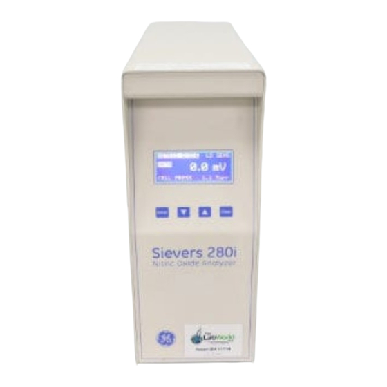
Summary of Contents for GE MOA 280i
- Page 1 Sievers Nitric Oxide Analyzer NOA 280i Operation and Maintenance Manual Firmware Version 3.00 and later 6060 Spine Road Boulder, CO 80301 USA phone 800.255.6964 • 303.444.2009 fax 303.444.9543 DLM 14291 Rev A www.geinstruments.com Printed in USA ©2006...
- Page 2 NOA and the front of the vacuum pump. Analyzer serial no. Pump serial no. Warranty Start Date Date of receipt/Installation *Trademark of General Electric Company; may be registered in one or more countries. GE Analytical Instruments ©2006 DLM 14291 Rev. A...
- Page 3 No part of this document may be photocopied or reproduced without the prior written consent of Sievers Instruments, Inc. Initial Printing December 2000 DLM 14290-01 Revision A March 2001 DLM 14291 Revision A May 2006 Printed in USA GE Analytical Instruments ©2006 DLM 14291 Rev. A...
- Page 4 6964), Monday - Friday, from 8:00 a.m. to 5:00 p.m. (Mountain Time), excluding all company and legal holidays. Telephone support is provided for troubleshooting and determination of parts to be shipped from GE Analytical Instruments to the customer in order to return the product to operation. If telephone support is not effective, the product may be returned to GE Analytical Instruments for repair or replacement.
- Page 5 Instruments will pay freight charges, exclusive of any taxes and duties, for replacement or repaired products shipped to the customer site. Customers shall pay freight charges, including all taxes and duties, for all products returning to GE Analytical Instruments. Any product returned to the factory without an RA number will be returned to the customer.
- Page 6 GE Analytical Instruments ©2006 DLM 14291 Rev. A...
-
Page 7: Table Of Contents
............................3-8 INSTALLATION............................4-1 OCATION ................................ 4-1 OWER EQUIREMENTS ............................. 4-1 NVIRONMENTAL ONSIDERATIONS ........................4-2 OOLS AND DDITIONAL UPPLIES ........................4-2 Tools................................. 4-2 Gases ................................ 4-2 Data Collection............................4-2 ACUUM ETUP ............................4-4 GE Analytical Instruments ©2006 DLM 14291 Rev. A... - Page 8 ALIBRATION OF PPB AND PPM ANGES ..................6-8 CCURACY OF PPB LEVEL EASUREMENTS USING PPM LEVEL ALIBRATION ............. 6-9 NOA 280 ESPONSE HARACTERISTICS OF ................... 6-10 ALIBRATION AT OWER ATES ......................6-11 viii GE Analytical Instruments ©2006 DLM 14291 Rev. A...
- Page 9 Disconnecting the bag from the filler and sealing the bag............8-11 NALYZING THE AMPLES ..........................8-11 Analysis Setup............................8-11 NOA S ETUP ..............................8-11 LEANING THE ..........................8-13 Vital Capacity Bag Kit ......................... 8-13 Deadspace Discard Bag Kit ......................... 8-14 GE Analytical Instruments ©2006 DLM 14291 Rev. A...
- Page 10 Zinc Sulfate/Sodium Hydroxide precipitation ................11-11 MEASUREMENT OF NITRIC OXIDE AND NITRITE IN LIQUID SAMPLES........12-1 PPARATUS FOR ITRITE EDUCTION ....................... 12-1 REPARATION OF THE ITRITE EDUCING GENT ....................12-2 DJUSTMENT OF URGE ......................12-3 GE Analytical Instruments ©2006 DLM 14291 Rev. A...
- Page 11 Serum and Plasma Samples ......................13-10 ITRATE ONTAMINATION ..........................13-11 EPLACING THE EDUCING GENT AND PENING THE URGE ESSEL ............... 13-11 PENING THE UBBLER .......................... 13-12 EPTUM EPLACEMENT ..........................13-13 LEANING THE URGE ESSEL ........................13-13 GE Analytical Instruments ©2006 DLM 14291 Rev. A...
- Page 12 TROUBLESHOOTING ........................16-1 RRORS ................................16-1 OSSIBLE RRORS AND EMEDIES ........................16-2 E 01 – Setup Data Corrupted, Check Before Running ..............16-2 E 02 – Cell Pressure was Above the Limit ..................16-2 GE Analytical Instruments ©2006 DLM 14291 Rev. A...
- Page 13 Low Conversion for Nitrate..........................16-13 Poor Repeatability..........................16-13 Syringe Problems ............................. 16-14 Foaming of theVCl Reagent.......................... 16-14 Injection Technique ............................16-14 Contamination ..............................16-14 High background Signal and Rising Baselines................16-15 Ghost Peaks............................16-15 xiii GE Analytical Instruments ©2006 DLM 14291 Rev. A...
- Page 14 GE Analytical Instruments ©2006 DLM 14291 Rev. A...
-
Page 15: Introduction
S-nitroso compounds, amines to form nitrosamines, and metals to form metal-nitrosyl complexes. In the gas phase, NO reacts with high concentrations of oxygen to form nitrogen dioxide. GE Analytical Instruments ©2006 DLM 14291 Rev. A... - Page 16 Intentional interruption is prohibited. WARNING: This symbol indicates that to comply with European Union Directive 2002/96/EC for waste electrical and electronic equipment (WEEE), the Analyzer should be disposed of separately from standard waste. GE Analytical Instruments ©2006 DLM 14291 Rev. A...
- Page 17 Gerät eingebauten Schutzvorrichtungen beeinträchtigt valables. werden. WARNHINWEIS: ATTENTION: Die Entsorgung der Lithium-Batterie in der RAM-Karte darf nur nach den Les batteries RAM Card Lithium doivent être déposés suivant les régulations geltenden Umweltschutzregeln erfolgen. d’environnement locales. GE Analytical Instruments ©2006 DLM 14291 Rev. A...
- Page 18 ATTENZIONE: OPGELET: Le batterie al Litio sulla RAM CARD, quando sono esaurite, devono RAM kaart Lithium batterijen dienen volgens de lokale essere gettate secondo le regolamentazioni vigenti localmente. afvalwetgeving verwijderd te worden. GE Analytical Instruments ©2006 DLM 14291 Rev. A...
-
Page 19: Sample Inlet Systems
® includes a Nafion drier, 0.45 µm particle filter, PVC sampling lines with ® Luer adapters and a calibration tee. Figure 1-1: Schematic of Model 280i Nitric Oxide Analyzer GE Analytical Instruments ©2006 DLM 14291 Rev. A... -
Page 20: Chemiluminescent Reaction Chamber And Optical Filter
~2% by volume from oxygen. This large excess of ozone is sufficient for measurement of NO up to 500 ppm. Chemiluminescent Reaction Chamber and Optical Filter GE Analytical Instruments ©2006 DLM 14291 Rev. A... -
Page 21: Photomultiplier Tube And Cooled Housing
The microprocessor keeps track of the trap and oil lifetimes, and notifies the user when it is time to replace the traps or change the oil. Electronics There are 7 circuit boards in the NOA: GE Analytical Instruments ©2006 DLM 14291 Rev. A... -
Page 22: Analog, Printer And Rs-232 Outputs
5 seconds to 10 minutes. The RS-232 output provides data at sampling rates from 32 samples per second to 6 samples per minute. GE Analytical Instruments ©2006 DLM 14291 Rev. A... -
Page 23: Exhalation Pressure Transducer
Chapter 14 describes the measurement of nitrosothiols and other reaction products in liquid samples. • Chapter 15 describes maintenance of the NOA. • Chapter 16 lists troubleshooting procedures and error and warning messages. GE Analytical Instruments ©2006 DLM 14291 Rev. A... -
Page 25: Specifications
Display ........... Back-lit LCD screen ............ ppb/ppm or mV Outputs ............ Analog 0 – 1V, 0 – 10 V ............ Digital RS-232 (9600-38.4K baud) ............ Printer parallel port Data Sampling Rate ......0.002 - 32 samples/second GE Analytical Instruments ©2006 DLM 14291 Rev. A... - Page 26 Main Fuse ........100 VAC model: T, 10A, 250V 120 VAC model: T, 5A, 250V 230 VAC model: T, 5A, 250V Ozone Fuse........100VAC model: T, 200mA, 250V 120 VAC model: T, 200mA, 250V 230 VAC model: T, 100mA, 250V GE Analytical Instruments ©2006 DLM 14291 Rev. A...
-
Page 27: Menus And Control Overview
ENTER button. Status Screen Press the CLEAR button from the Main Menu to display the Status Screen. This screen shows the current values for the PMT cooler temperature, reaction cell GE Analytical Instruments ©2006 DLM 14291 Rev. A... -
Page 28: Analysis
• Check the cell pressure to see if it is above 300 torr, then turn on the pump. A N A L Y S I S S T A R T S T A N D - B Y Figure 3-3: Analysis Menu with NOA in Stop Mode. GE Analytical Instruments ©2006 DLM 14291 Rev. A... -
Page 29: Measurement Menu
Screen to aid in troubleshooting failed tests. Pressing CLEAR will return to the Analysis Menu. Measurement Menu Once the start-up testing is completed, the Measurement Menu is displayed. Figure 3-5:Measurement Menu (Nitric Oxide Mode) GE Analytical Instruments ©2006 DLM 14291 Rev. A... - Page 30 Measurement Menu. In the Exhalation mode, a bar graph of the exhalation pressure is displayed. From the Measurement Menu, pressing the CLEAR button will return to the Main Menu and from the Main Menu, pressing CLEAR will return to the Measurement Menu. GE Analytical Instruments ©2006 DLM 14291 Rev. A...
- Page 31 Stand-by option will turn off the PMT and ozone generator, but leave the vacuum pump on. If the analysis was stopped, selecting the Stand-by option will turn on the vacuum pump. GE Analytical Instruments ©2006 DLM 14291 Rev. A...
-
Page 32: Main Menu Options
The Control Menu also permits viewing of the cooler temperature C O N T R O L M E T H O D S E T U P S T A T U S Figure 3-8: Control Menu. GE Analytical Instruments ©2006 DLM 14291 Rev. A... -
Page 33: Calibration
Errors indicate that the cooler temperature or the supply or cell pressures are out of range. When an error is detected, the NOA is placed in the Stop Mode and the firmware switches to the Errors menu. GE Analytical Instruments ©2006 DLM 14291 Rev. A... -
Page 34: Maintenance
10 minutes, the firmware will return to the Main Menu, if the NOA is in the Stop or Standby Mode or the Measurement Menu if the NOA is in the Start Mode. GE Analytical Instruments ©2006 DLM 14291 Rev. A... -
Page 35: Installation
For 230 VAC versions of the detector, a standard (230 VAC, 50 Hz) grounded AC outlet (~3 amps) is required. For 100 VAC versions, a standard (100 VAC, 50 or 60 Hz) grounded AC outlet (~7 amps) is required. GE Analytical Instruments ©2006 DLM 14291 Rev. A... -
Page 36: Environmental Considerations
USB-Serial adapter is required. For real-time display of the analog signal, a strip chart recorder or integrator may be used. The analog signal can also be sent to a computer using an analog- GE Analytical Instruments ©2006 DLM 14291 Rev. A... - Page 37 ® to-digital converter. For the printer output, any Centronics style printer can be used. Contact Sievers Instruments with any questions regarding data collection equipment. GE Analytical Instruments ©2006 DLM 14291 Rev. A...
-
Page 38: Vacuum Pump Setup
Step 2 - Install Pump Inlet Fitting Remove the plastic caps from inlet and outlet of the pump. Locate the barbed inlet fitting and clamp in the pump accessories kit. Place the barbed fitting on the GE Analytical Instruments ©2006 DLM 14291 Rev. A... -
Page 39: Step 3- Install The Chemical Trap Mounting Bracket
Locate the Hopcalite trap in the NOA accessories box and the short length of clear Charcoal Trap Mounting Bracket for Charcaol Trap Hopcalite Trap Figure 4-2: RV3 Pump with Chemical and Charcoal Traps. GE Analytical Instruments ©2006 DLM 14291 Rev. A... -
Page 40: Step 4 - Install The Pump Outlet Fitting
Place a hose clamp over the end of the vacuum hose (Tygon tubing with black heat shrink and a metal fitting on one end), and connect the hose to the barbed fitting GE Analytical Instruments ©2006 DLM 14291 Rev. A... - Page 41 Hopcalite trap. Use a 5/16” hexdriver or a regular screwdriver to tighten the hose clamp. GE Analytical Instruments ©2006 DLM 14291 Rev. A...
- Page 42 Figure 4-3: NOA Back Panel. GE Analytical Instruments ©2006 DLM 14291 Rev. A...
-
Page 43: Step 6 - Connect Power Cord To Vacuum Pump And Turn On Pump Power Switch
This will require some force to get a good seal. Vacuum Test Once the vacuum pump has been connected, test that all connections are tight by performing a vacuum test. Make sure the power switch on the vacuum pump is in GE Analytical Instruments ©2006 DLM 14291 Rev. A... - Page 44 ENTER. The display will change with Continue and Stop options. Select Stop to turn off the vacuum pump. Leave the main power switch ON while completing the installation to cool the PMT. 4-10 GE Analytical Instruments ©2006 DLM 14291 Rev. A...
-
Page 45: Gas For Ozone Generator
Oxygen tubing with 22 mm connectors, universal oxygen tubing or bubble tubing can be used to connect the barbed connector of the flow controller to the NOA. In the 4-11 GE Analytical Instruments ©2006 DLM 14291 Rev. A... -
Page 46: Frit Restrictor
NOA and secure with the thumbscrews. Connect the 9 pin female end to the computer’s COM Port. Some desktop PCs have 25 pin Com Ports and require a 9 4-12 GE Analytical Instruments ©2006 DLM 14291 Rev. A... -
Page 47: Setting The Clock
/ t i m e E N T a c c e p t C L R r e j e c t display the Control Menu. 4-13 GE Analytical Instruments ©2006 DLM 14291 Rev. A... -
Page 48: Configuration Menu Options
Lower baud rates will limit the Com port intervals that can be used. At 19200 or 9600, the 1/32 interval cannot be used and some data loss may be observed at an interval of 1/16. 4-14 GE Analytical Instruments ©2006 DLM 14291 Rev. A... -
Page 49: Configuration Menu
Arrow buttons to scroll to the desired units, I N S T A L L press Enter and when the confirmation screen is shown, press ENTER to save the new units. 4-15 GE Analytical Instruments ©2006 DLM 14291 Rev. A... -
Page 50: Setting The Consumables Installation Data
Pump Oil Menu will indicate that the installation was accepted and then return to the Install Menu. • Repeat the installation process for the Hopcalite, Cell and Cooler by selecting each item from the Install menu, pressing ENTER, then selecting Install. Start-up 4-16 GE Analytical Instruments ©2006 DLM 14291 Rev. A... - Page 51 The Startup screen is displayed and the NOA should pass all tests and display the Measurement Menu. If the NOA fails any tests, consult the Troubleshooting section (Chapter 14) for assistance. 4-17 GE Analytical Instruments ©2006 DLM 14291 Rev. A...
-
Page 53: Installation And Setup: Gas-Phase Measurements
• Connect the bacterial filter to the Luer bulkhead fitting labeled “Breath Pressure” on the NOA back panel. • Connect the Pressure line (clear PVC tubing with white Luer adapters on ends) to the bacterial filter. GE Analytical Instruments ©2006 DLM 14291 Rev. A... -
Page 54: Installation Of Thermal Mass Flowmeter
• Locate the metal flow meter clamp and phillips-head screw from the flow meter kit and install the clamp on the NOA’s side panel. Figure 5-1: Gas Sampling Package GE Analytical Instruments ©2006 DLM 14291 Rev. A... - Page 55 • Remove the adhesive backing and secure the cable clamp to the NOA’s top cover, near the back (below the gas sampling clamp). • Secure the flow meter cable using the clamp. GE Analytical Instruments ©2006 DLM 14291 Rev. A...
-
Page 56: Noa Setup For Gas-Phase Measurements
• From the Analysis Setup Menu, select Modes. S E L E C T E X H A L A T I O N • From the Modes Menu, select Select. • From the Select Modes Menu, select Exhalation GE Analytical Instruments ©2006 DLM 14291 Rev. A... - Page 57 • From the Exh Press Unit Menu, scroll to the desired pressure unit and press ENTER. • A confirmation screen is shown, press ENTER to change the unit. To change the desired pressure (pressure value for arrow on Measurement Menu): GE Analytical Instruments ©2006 DLM 14291 Rev. A...
- Page 58 L O W return to the Analysis Setup Menu. • From the Analysis Setup Menu, select Operation • From the Operation Setup Menu, select Sensitivity. • Scroll to the desired sensitivity and press ENTER. GE Analytical Instruments ©2006 DLM 14291 Rev. A...
-
Page 59: Nitric Oxide Mode
Units must be set to Concentration. To set the Units • With the NOA in the Nitric Oxide Mode (see above for setting the mode), from the Analysis Setup Menu, select Operation. GE Analytical Instruments ©2006 DLM 14291 Rev. A... - Page 60 • From the Operation Setup Menu, select Units • From the Units Menu select Concentration. The Sensitivity can be set to High. Low or Auto as described above. GE Analytical Instruments ©2006 DLM 14291 Rev. A...
-
Page 61: Calibration
Cylinders of breathing air, nitrogen or oxygen may or may not contain NO at ppb levels and should not be used for the Zero Gas Calibration unless they contain < 1 ppb of NO. GE Analytical Instruments ©2006 DLM 14291 Rev. A... -
Page 62: Calibration With Zero Air Filter
• Use the arrow buttons to scroll to Calibration and press ENTER. • The Calibration Menu is displayed with three options: Calibrate, View and Print. • Select Calibrate to display the Login menu. GE Analytical Instruments ©2006 DLM 14291 Rev. A... - Page 63 Replicate zero gas calibrations should agree within 1 or 2 counts. If the calibrations are drifting, continue sampling the zero air until stable replicate calibrations are obtained. GE Analytical Instruments ©2006 DLM 14291 Rev. A...
-
Page 64: Zero Gas Calibration Warnings
NO Calibration Gas The second step in the calibration is to determine the response of the NOA for a known concentration of nitric oxide. The preferred method is to use a gas GE Analytical Instruments ©2006 DLM 14291 Rev. A... - Page 65 . 9 0 . 0 • Select the gas units (PPM) and press C L R e s c a p e ENTER to display the Calib Gas Conc Menu. GE Analytical Instruments ©2006 DLM 14291 Rev. A...
-
Page 66: Calibration Gas Warnings
0 . 2 4 3 1 N E W P P B 0 . 4 7 8 1 E N T a c c e p t C L R r e c e c t GE Analytical Instruments ©2006 DLM 14291 Rev. A... - Page 67 14 has a procedure for testing and correcting light leaks. If the PMT signal is not stable during the calibration, an unstable calibration warning will be displayed. This can be caused by too low of cal gas flow or loose GE Analytical Instruments ©2006 DLM 14291 Rev. A...
-
Page 68: Calculation Of Gas Concentration
1:100 dilution of a 10 ppm NO standard with zero air to prepare a 100 ppb standard, and then dilute this gas 1:10 with zero air to prepare a 10 ppb standard. GE Analytical Instruments ©2006 DLM 14291 Rev. A... -
Page 69: Accuracy Of Ppb Level Measurements Using Ppm Level Calibration
NO can be prepared by dilution, but special equipment is required to accurately dilute gases. Most laboratories will get the most accurate (and less expensive) measurements by using a 10-100 ppm level calibration gas and using the calibrate PPM&PPB option. GE Analytical Instruments ©2006 DLM 14291 Rev. A... -
Page 70: Flow/Response Characteristics Of Noa 280I
The standard flow restrictor provides a flow of ~200 mL/min into the analyzer. For measurement of exhaled NO in small animals and some other applications, operation at lower flow rates may be required. For these applications, flow 6-10 GE Analytical Instruments ©2006 DLM 14291 Rev. A... -
Page 71: Calibration At Lower Flow Rates
Contact Sievers Instrument for the procedure to set the high voltage with the lower flow restrictors. If the high voltage is not adjusted, the NOA will report a response out of recommended limits” message during calibration. 6-11 GE Analytical Instruments ©2006 DLM 14291 Rev. A... -
Page 73: On-Line Exhaled Nitric Oxide
10% of the mean value or two measurements agree within 5% of the mean. † U.S. Patent Nos 5,795,787 and 6,010,459.Under license from Aperon Biosystems, Inc. GE Analytical Instruments ©2006 DML 14291 Rev. A... -
Page 74: Assembly Of The Accurate No Breath Kit
• Unscrew the clear exhaust port fitting from the valve, making sure the spiral diaphragm valve remains inside the non-rebreathing valve. • Install the Sievers exhaust port with a Luer adapter by screwing the port into the valve until secure. GE Analytical Instruments ©2006 DML 14291 Rev. A... -
Page 75: Connection Of Thermal Mass Flowmeter
For ease of use, cable ties or twist ties can be used along the length of the gas sampling and pressure lines to connect the two pieces of tubing. If the flowmeter is being used, the flowmeter’s signal cable and the gas sampling and pressure lines GE Analytical Instruments ©2006 DML 14291 Rev. A... -
Page 76: Inspiratory Gas Connections
Sensitivity set to Auto and the Com Port Interval set to 1/16 or 1/8. See Chapter 5 (INSTALLATION AND SETUP: GAS-PHASE MEASUREMENTS) for configuring the NOA. The NOA should be calibrated (Chapter 6–CALIBRATION) prior to measurement. GE Analytical Instruments ©2006 DML 14291 Rev. A... -
Page 77: Performing The Maneuver
(~ 20 seconds after start of exhalation). Figure 7-4 shows an exhalation Time (sec) with high ambient NO, but using the inspiratory Figure 7-4: Plateau with High Inspired NO and Filter. GE Analytical Instruments ©2006 DML 14291 Rev. A... -
Page 78: Selection Of No Plateau
Selection of NO Plateau recommendations define the plateau as the first 3 second interval seconds for children < igure 7-5: Possible NO Plateaus. GE Analytical Instruments ©2006 DML 14291 Rev. A... - Page 79 For decreasing NO plateaus, the beginning [NO] minus the end [NO] divided by the end [NO] must be < 10%, the [NO] during the interval must be less than the Figure 7-6: Flow/Pressure Calibrations for Restrictors GE Analytical Instruments ©2006 DML 14291 Rev. A...
-
Page 80: Flow/Pressure Characteristics Of Accurate No Restrictors
30 to 250 mL/s BTPS for use with the following models. The published models include: Tsoukias, N.M., George, S.C. “A two-compartment model of pulmonary nitric oxide exchange dynamics”. J Appl Physiol 1998; 85(2): 653-666. GE Analytical Instruments ©2006 DML 14291 Rev. A... -
Page 81: Cleaning The Accurate No Breath Kit And Flowmeter
• Remove the restrictor from the Luer adapter and unscrew the modified exhalation port. • Remove the exhalation diaphragm from the valve and remove the diaphragm from its ring. GE Analytical Instruments ©2006 DML 14291 Rev. A... -
Page 82: Prewash The Components
After drying, inspect all components to ensure that they are free from residue, not deformed or cracked. Reassemble the components by: • Placing the diaphragms back on their rings, making sure the flange is seated in the ring groove. 7-10 GE Analytical Instruments ©2006 DML 14291 Rev. A... -
Page 83: Checking The Inspiratory Gas Filter
• Note the [NO] on the NOA’s front panel. If the filter is operating properly, the [NO] should be < 5 ppb. If the [NO] is > 5 ppb, replace the inspiratory filter. 7-11 GE Analytical Instruments ©2006 DML 14291 Rev. A... -
Page 85: Off-Line Exhaled Nitric Oxide (Bag Sampling)
0 cm H O. Replace the clear plastic cover of the gauge. GE Analytical Instruments ©2006 DLM 14291 Rev. A... -
Page 86: Assembly Of Deadspace Discard Bag Collection Kit
Screw the filter onto the threaded end of the body. The Bag Kit is now ready for use. Assembly of Deadspace Discard Bag Collection Kit GE Analytical Instruments ©2006 DLM 14291 Rev. A... - Page 87 The bag collection kit must be assembled before use (refer to Figure 8-2). To assemble the kit: • Remove all packages from the shipping container. Remove the Body of the Sampler (the valves, pin, screw and adapters are already installed). GE Analytical Instruments ©2006 DLM 14291 Rev. A...
- Page 88 0 cm H O. Replace the clear plastic cover of the gauge. Figure 8- 2: Diagram of Deadspace Discard Bag Collection Kit. GE Analytical Instruments ©2006 DLM 14291 Rev. A...
-
Page 89: Cleaning The Bags
If ambient NO levels are high, this can contaminate the bag. The best procedure is to use a 3-way valve, with one leg connected to the zero air filter, one leg to the vacuum source GE Analytical Instruments ©2006 DLM 14291 Rev. A... -
Page 90: Collecting The Samples - Vital Capacity Bag Kit
Store the bags in a clean, dry and secure location. Reinstall the restrictor before using the NOA for gas analysis. Bags cleaned by this procedure will remain low in NO for approximately 24 hours. Collecting the Samples – Vital Capacity Bag Kit GE Analytical Instruments ©2006 DLM 14291 Rev. A... -
Page 91: Connecting The Bag To The Filler
13 cm H O to give an expiratory flow rate of 0.35 L/s.* During the exhalation, the pressure should * at 760 torr, for other pressures, calculate the required pressure from the equation: GE Analytical Instruments ©2006 DLM 14291 Rev. A... - Page 92 Normally, subjects will fill three bags, and the average NO concentrations in these three samples is used for the subject’s FE Subjects NO, 0.35. should rest a few minutes between exhalations. 0.5851 Flow = (760/P (torr)) * 79.3 * P GE Analytical Instruments ©2006 DLM 14291 Rev. A...
-
Page 93: Collecting The Samples - Deadspace Discard Bag Kit
• Pull the valve stem on the filler to the out position (see Figure 8-4). • Open a new viral and bacterial filter and connect the filter to the tapered end on the top of the filler. • Connect a sterile mouthpiece to the filter. GE Analytical Instruments ©2006 DLM 14291 Rev. A... -
Page 94: Instructing The Subject And Collecting The Samples
5 to 6 seconds to collect 250 to 300 mL of gas in the bag. * at 760 torr, for other pressures, calculate the required pressure from the equation: 0.533 Flow = (760/P (torr)) * 21.1 * P 8-10 GE Analytical Instruments ©2006 DLM 14291 Rev. A... -
Page 95: Disconnecting The Bag From The Filler And Sealing The Bag
Connect the NO sample line to the other female Luer leg of the three-way valve. The bags will be connected to the male Luer leg of the valve. NOA Setup 8-11 GE Analytical Instruments ©2006 DLM 14291 Rev. A... - Page 96 • Record the NO value from the display or select the Add NO value button in the Bag program. • Turn the valve back so that OFF points toward the bag. Figure 8-5: Setup for Analysis of Bag Samples. 8-12 GE Analytical Instruments ©2006 DLM 14291 Rev. A...
-
Page 97: Cleaning The Bag Kits
• Screw the large knurled fitting onto the threaded end of the body. • Screw the inspiratory filter onto the knurled fitting. • Screw the pressure gauge into the bag filler body. 8-13 GE Analytical Instruments ©2006 DLM 14291 Rev. A... -
Page 98: Deadspace Discard Bag Kit
• Screw the large knurled fitting onto the threaded end of the body. • Screw the inspiratory filter onto the knurled fitting. • Screw the pressure gauge into the bag filler body. Flow/Pressure Characteristics of Bag Kits 8-14 GE Analytical Instruments ©2006 DLM 14291 Rev. A... -
Page 99: Stability Of No In Mylar Bags
48 hours (Massaro et. al., Am. J. Respir. Crit Care Med 1995, 152, 800- 803). Sievers testing has shown that NO concentrations slowly increases over time with a small but significant increase (1-2 ppb) observed after 8-12 hours. This 8-15 GE Analytical Instruments ©2006 DLM 14291 Rev. A... - Page 100 NO. One way to monitor possible increases in the concentration of NO in the bags, particularly when there is a long time between collection and analysis of samples 8-16 GE Analytical Instruments ©2006 DLM 14291 Rev. A...
-
Page 101: Off-Line Versus On-Line Exhaled No Measurements
WARNING: DO NOT FILL THE BAGS WITH PPM LEVELS OF NO FOR THESE TESTS. HIGH CONCENTRATIONS OF NO WILL ABSORB ON THE WALLS OF THE BAGS AND IS DIFFICULT TO REMOVE. 8-17 GE Analytical Instruments ©2006 DLM 14291 Rev. A... - Page 102 If ambient NO is lower than the NO concentration in the bag a decrease in NO can be observed. Discard any bags that show large changes in NO concentration. 8-18 GE Analytical Instruments ©2006 DLM 14291 Rev. A...
-
Page 103: Breath-By-Breath And Chamber Sampling For Exhaled Nitric Oxide
NO air can be used for the inspiratory gas Figure 9- 1: Setup for Breath-by-Breath and the sampling port must be Sampling (spontaneously breathing subject). positioned to allow alternate GE Analytical Instruments ©2006 DLM 14291 Rev. A... -
Page 104: Ventilated Subjects
The NOAnalysis Breath program detects the beginning and end of exhalations based on changes in the exhalation pressure and reports maximum, minimum and end-tidal NO values for each breath. GE Analytical Instruments ©2006 DLM 14291 Rev. A... -
Page 105: Noa Setup
4 torr if the filter is blocked by liquid water. The Nafion drier after the filter eliminates any problems in the sensitivity of the NOA due to water vapor in the circuit. GE Analytical Instruments ©2006 DLM 14291 Rev. A... -
Page 106: Chamber Sampling
NO from urine and feces. The measurement consists of four steps: • The animal is placed in the chamber. • The stopcocks are positioned to flush the head-out chamber with low NO air. GE Analytical Instruments ©2006 DLM 14291 Rev. A... - Page 107 The best procedure is to start with a short collection period to see if enough NO accumulates to give a significant increase above the background NO and increase the period if not enough NO accumulates. GE Analytical Instruments ©2006 DLM 14291 Rev. A...
-
Page 108: Noa Setup
Auto and the Com Port Interval set to 1/2 or 1/4 second. See Chapter 5 (INSTALLATION AND SETUP: GAS-PHASE MEASUREMENTS) for configuring the NOA. The NOA should be calibrated (Chapter 6 – CALIBRATION) prior to measurement. GE Analytical Instruments ©2006 DLM 14291 Rev. A... -
Page 109: 10. Nasal Nitric Oxide
• A vacuum source capable of drawing 3-6 L/min. • A rotometer or other flow control device for regulating the flow into the vacuum source. • Tubing to connect the vacuum source. 10-1 GE Analytical Instruments ©2006 DLM 14291 Rev. A... -
Page 110: Performing The Maneuver
The oral exhalation flow rate is not important. The 50 mL/s restrictor is suitable for most subjects. ATS recommends a target pressure of 10 cm H O to ensure vellum closure. 10-2 GE Analytical Instruments ©2006 DLM 14291 Rev. A... -
Page 111: Noa Setup
The NOAnalysis REB or Bag program can be used for data acquisition. If the Bag program is used, the subject must watch the NOA’s front panel to maintain the 10-3 GE Analytical Instruments ©2006 DLM 14291 Rev. A... - Page 112 10 cm H O. See the NOAnalysis manual for operation of these programs. 10-4 GE Analytical Instruments ©2006 DLM 14291 Rev. A...
-
Page 113: 11. Installation And Setup: Liquid Measurements
50% NaOH (aq) Nitrosothiols – Thiols (glutathione, N-acetyl cysteine, albunin, hemoglobin) PBS, Cu(I)Cl, cysteine, or I , CuSO4, HgCl , reagents for nitrite Iron-bound NO – KCN, K FeCN Lab Equipment 11-1 GE Analytical Instruments ©2006 DLM 14291 Rev. A... -
Page 114: Setup Of Purge Vessel
• Support the purge vessel on a ring stand using a three-finger jaw clamp to secure the middle of the purge vessel. The side of the clamp with a single 11-2 GE Analytical Instruments ©2006 DLM 14291 Rev. A... -
Page 115: Connections Of Tubing To Glassware
Support the gas bubbler-NaOH trap on the same ring stand using a clamp. Connections of tubing to glassware Figure 11-1:Purge Vessel and Gas Bubbler-NaOH trap. Figure 11-2: Connections to Glassware 11-3 GE Analytical Instruments ©2006 DLM 14291 Rev. A... -
Page 116: Procedure For Tightening Swagelok Fittings
When the fitting is tight, the union cannot be easily rotated with two fingers. Since the Teflon ferrules will slide on the glass, the union can be rotated when the fitting is tight, but some force will be required to turn the union. 11-4 GE Analytical Instruments ©2006 DLM 14291 Rev. A... - Page 117 (Figure 11-3). Figure 11-1: Connections for Hot and Cold Water for Nitrate Reduction. 11-5 GE Analytical Instruments ©2006 DLM 14291 Rev. A...
- Page 118 11-6 GE Analytical Instruments ©2006 DLM 14291 Rev. A...
-
Page 119: Dilution Of Anti-Foaming Agent
Dilution of Anti-foaming Agent Included with the purge vessel is a small vial containing a silicon emulsion, anti- foaming agent. This material must be diluted 1:30 with deionized water and 100 11-7 GE Analytical Instruments ©2006 DLM 14291 Rev. A... -
Page 120: Noa Setup For Liquid Measurements
MO D E S S E T U P Option): S E L E C T E X H A L A T I O N • From the Main Menu, select Control. 11-8 GE Analytical Instruments ©2006 DLM 14291 Rev. A... - Page 121 : L O W • From the Operation Setup Menu, select Units. • From the Units Menu, Select Voltage. • Press CLEAR to return to the Operation Setup Menu. 11-9 GE Analytical Instruments ©2006 DLM 14291 Rev. A...
-
Page 122: Deproteinization Procedures
Any deproteinization procedure can be used and two techniques that have been successfully employed are listed. Contamination from nitrite or nitrate can occur during these procedures, especially if the 11-10 GE Analytical Instruments ©2006 DLM 14291 Rev. A... -
Page 123: Cold Ethanol Precipitation
• Vortex for 30 seconds then let stand at room temperature for 15 minutes. • Centrifuge at ~14,000 RPM for 5 minutes. • Remove supernatant for analysis (remember to account for 5-fold dilution in the calculations). 11-11 GE Analytical Instruments ©2006 DLM 14291 Rev. A... -
Page 125: Measurement Of Nitric Oxide And Nitrite In Liquid Samples
The outlet of the IFD is connected to the inlet of the standard flow restrictor (do not use the Nafion drier). reduction Figure 12-1: Setup for Nitrite Measurement 12-1 GE Analytical Instruments ©2006 DLM 14291 Rev. A... -
Page 126: Preparation Of The Nitrite Reducing Agent
• Transfer the iodide solution to the purge vessel containing the acid and continue to purge for a few minutes to aid in mixing the reagent. • Add 100 µL of the dilute antifoaming agent to the purge vessel. 12-2 GE Analytical Instruments ©2006 DLM 14291 Rev. A... -
Page 127: Adjustment Of Purge Gas Flow Rate
When the gas flow rate is properly adjusted, the purge vessel will be under a slight vacuum and the level of the reducing agent should be near the top of the purge 12-3 GE Analytical Instruments ©2006 DLM 14291 Rev. A... - Page 128 Once the bubbling slows, close the gas inlet stopcock. Release any pressure in the purge vessel by slowly opening the screw cap and then drain some of the reagent using the drain stopcock. 12-4 GE Analytical Instruments ©2006 DLM 14291 Rev. A...
-
Page 129: Preparation Of Stock Solution
10 nM, 50 nM, 100 nM, 1 µM, 5 µM, 10 µM, 50 µM and 100 µM will allow construction of a calibration curve suitable for most cell culture work. For stimulated macrophages and other cell types that produce high levels of NO, 12-5 GE Analytical Instruments ©2006 DLM 14291 Rev. A... - Page 130 100 µM. 12-6 GE Analytical Instruments ©2006 DLM 14291 Rev. A...
-
Page 131: Preparation Of Dilute Standards
• Set aside or discard the two most concentrated standards (10 mM and 1 mM) as these will not be used. WARNING: ALWAYS USE NEW PIPETTE TIPS FOR EACH DILUTION. SOME NITRITE REMAINS IN THE TIP AND WILL CONTAMINATE SUBSEQUENT DILUTIONS. 12-7 GE Analytical Instruments ©2006 DLM 14291 Rev. A... -
Page 132: Water Blanks
The Time (secs) peak size decreases with additional water Figure 12-2: Typical Peaks from Injections of Water 12-8 GE Analytical Instruments ©2006 DLM 14291 Rev. A... -
Page 133: Injection Technique
If the NOA output signal reaches 1000 mV, the linear range for the High Sensitivity setting of the amplifier has been exceeded and the top of the peak has been “cut- 12-9 GE Analytical Instruments ©2006 DLM 14291 Rev. A... -
Page 134: Repeatability
If the glassware, pipettes, and other equipment are contaminated with nitrite, then the actual concentration of NO in the standards will be higher than expected. Rinse all equipment with nitrite-free deionized 12-10 GE Analytical Instruments ©2006 DLM 14291 Rev. A... - Page 135 Water exposed to the atmosphere can absorb nitric oxide, which will be converted to nitrite. It is best to use water fresh from the purification system and minimize its exposure to air to avoid contamination. 12-11 GE Analytical Instruments ©2006 DLM 14291 Rev. A...
-
Page 136: Sample Analysis
(for example, 1 µL, 10 µL and 100 µL) and observe how much foaming occurs in the purge vessel. Deproteinization procedures are described in Chapter 11 (page 11-10). Background Nitrite 12-12 GE Analytical Instruments ©2006 DLM 14291 Rev. A... -
Page 137: Replacing The Reducing Agent And Opening The Purge Vessel
100 µL of the dilute antifoaming agent. • Replace the screw cap and septum, the open the outlet stopcock and purge for a few minutes before analyzing water blanks, then samples or standards. 12-13 GE Analytical Instruments ©2006 DLM 14291 Rev. A... -
Page 138: Septum Replacement
• Open the outlet stopcock and use a squeeze bottle to rinse the sides of the condenser with water. 12-14 GE Analytical Instruments ©2006 DLM 14291 Rev. A... - Page 139 Tighten the 1/4" nut fingertight. Do not use a wrench to tighten the nut because the glass will break if the nut is overtightened (see Procedure for Tightening Swagelok Fittings page 11-4). 12-15 GE Analytical Instruments ©2006 DLM 14291 Rev. A...
-
Page 140: Cleaning Of The Ifd Filter
Two styles of IFD filters are sold by the supply houses, the polypropylene filter used in the NOA and a nylon filter. Always use the polypropylene filter with the NOA. Long-term maintenance of the purge vessel and bubbler 12-16 GE Analytical Instruments ©2006 DLM 14291 Rev. A... - Page 141 Use an ultrasonic cleaner to assist in cleaning. Rinse the purge vessel thoroughly in deionized water and allow to air dry before re-assembling the purge vessel. 12-17 GE Analytical Instruments ©2006 DLM 14291 Rev. A...
-
Page 143: Measurement Of Nitrate, Nitrite And Nitric Oxide In Liquid Samples
Figure 13-1 shows the setup for nitrate reduction. The outlet purge vessel connected bubbler/NaOH trap and the outlet bubbler Figure 13- 1: Setup for Nitrate Reduction connected to the inlet of the 13-1 GE Analytical Instruments ©2006 DLM 14291 Rev. A... -
Page 144: Preparation Of The Nitrate Reducing Agent
• The solution MUST be filtered before use. Any filter paper (such as Whatman #1) can be used to filter the solution. Store the solution in a clean screw-cap bottle with a Teflon or aluminum foil seal. Preparation of 1M NaOH 13-2 GE Analytical Instruments ©2006 DLM 14291 Rev. A... -
Page 145: Startup Procedures For Nitrate Reduction
Do not connect the IFD line to the NOA. • Connect the bubbler line tubing from the outlet of the purge vessel to the inlet of the bubbler. 13-3 GE Analytical Instruments ©2006 DLM 14291 Rev. A... -
Page 146: Adjustment Of Purge Gas Flow Rate
The cell pressure can be viewed at the bottom of the measurement menu or from the Control/Status screen. • Connect the IFD filter line to the NOA’s frit restrictor and tighten the nut fingertight. 13-4 GE Analytical Instruments ©2006 DLM 14291 Rev. A... -
Page 147: Leak Check For Purge Vessel
Other sources include the Swagelok connections (make sure the ferrules are in place and the connections are tight) and the connections at the IFD filter. Adjustment of Liquid Level 13-5 GE Analytical Instruments ©2006 DLM 14291 Rev. A... -
Page 148: Preparation Of Stock Solution
To prepare 10 mL of 100 mM NO • Weigh out ~85 mg of NaNO or ~101 mg of KNO directly into a 10 mL volumetric flask. • Record the weight of NaNO or KNO 13-6 GE Analytical Instruments ©2006 DLM 14291 Rev. A... -
Page 149: Preparation Of Dilute Standards
• Set one tube aside and label the tube Water Blank. • Add 100 µL of the stock solution to the first tube, mix thoroughly and label the tube 10 mM (Note: the actual concentration will depend on the 13-7 GE Analytical Instruments ©2006 DLM 14291 Rev. A... - Page 150 For amount-based calibrations, different volumes can be injected, but the volume must be included in the sample name. For a 10 µL syringe, injection 13-8 GE Analytical Instruments ©2006 DLM 14291 Rev. A...
-
Page 151: Water Blanks
• Rapidly depress the plunger to transfer the liquid into the purge vessel. • Withdraw the syringe, wipe the needle to remove any reducing agent and then rinse the syringe two or more times with deionized water. 13-9 GE Analytical Instruments ©2006 DLM 14291 Rev. A... -
Page 152: Preparation Of Calibration Curve
Samples containing protein will also change the viscosity of the VCl /HCl causing the level of the reagent to drop. Usually the level will return to near 13-10 GE Analytical Instruments ©2006 DLM 14291 Rev. A... -
Page 153: Nitrate Contamination
• Continue purging the solution with the inert gas until the flow of gas, as indicated by the gas bubbles, has stopped or slowed considerably. • Close the gas inlet stopcock to stop the flow of gas into the purge vessel. 13-11 GE Analytical Instruments ©2006 DLM 14291 Rev. A... -
Page 154: Opening The Gas Bubbler
• Once loose, slowly pull the union off the purge vessel while keeping an eye on the level of NaOH in the bubbler. As the union is removed, air will be 13-12 GE Analytical Instruments ©2006 DLM 14291 Rev. A... -
Page 155: Septum Replacement
To clean the purge vessel: • Follow the procedures above to drain the reducing agent from the purge vessel. 13-13 GE Analytical Instruments ©2006 DLM 14291 Rev. A... - Page 156 Replace the needle valve, and turn on the gas to force the water through the frit. Repeat this procedure 3 or 4 times to completely clean the frit and tubing. 13-14 GE Analytical Instruments ©2006 DLM 14291 Rev. A...
-
Page 157: Cleaning The Gas Bubbler
The water will be forced into the frit and squirt out the bubbler inlet tubing. • Repeat this process several times to remove any material inside the frit and tubing. 13-15 GE Analytical Instruments ©2006 DLM 14291 Rev. A... -
Page 158: Cleaning The Bubbler Tubing
• Remove the plastic nut and tubing on the inlet of the filter (the side with two ports) to bring the filter to atmospheric pressure and then remove the 13-16 GE Analytical Instruments ©2006 DLM 14291 Rev. A... -
Page 159: Long-Term Maintenance Of The Purge Vessel And Bubbler
Soak the purge vessel, bubbler, needle valves and stopcocks in warm detergent for several hours. Use an ultrasonic cleaner to assist in cleaning. Rinse the items thoroughly in deionized water and allow to air dry before re-assembling the purge vessel and bubbler. 13-17 GE Analytical Instruments ©2006 DLM 14291 Rev. A... - Page 160 13-18 GE Analytical Instruments ©2006 DLM 14291 Rev. A...
-
Page 161: 14. Other Liquid Measurement Techniques
The reagent can be used at room temperature, but more rapid conversions are obtained at elevated temperatures (50 °C). The highest response for GSNO was 14-1 GE Analytical Instruments ©2006 DLM 14291 Rev. A... -
Page 162: Preparation Of Nitrosothiols Standards
200 mM CuSO is added to the purge vessel. Due in part to the large sample volumes (100 – 2000 µL)), the reagent is replaced after each injection. 14-2 GE Analytical Instruments ©2006 DLM 14291 Rev. A... -
Page 163: Preparation Of S-Nitroso-Albumin
To eliminate response from iron-bound NO, the samples are pretreated with 100-fold excess of 0.2 M KCN and 0.2 M K Fe(CN) in 0.5 mM EDTA. Nitrite was removed through use of a Sephadex G25 column. Measurement of Iron-bound NO 14-3 GE Analytical Instruments ©2006 DLM 14291 Rev. A... -
Page 164: Headspace Measurement Of Nitric Oxide
NO produced will be oxidized and remain in the fluid. Headspace analysis can be used for a wide range of samples including cell cultures, tissue homogenates, and when combined with reducing agents, 14-4 GE Analytical Instruments ©2006 DLM 14291 Rev. A... -
Page 165: Apparatus For Headspace Analysis
The gas sample is then injected into the purge vessel and the Liquid program used to collect the data and integrate the peaks. In order to obtain a sharp NO peak, a sample should be injected as fast as possible. 14-5 GE Analytical Instruments ©2006 DLM 14291 Rev. A... -
Page 166: Preparation Of Standards For Headspace
NO-donor compounds rather than NO gas. A known concentration of an NO donor (e.g., SNAP, SNP, nonoates) is added to the sealed container, the sample is equilibrated and a headspace sample collected as described above. 14-6 GE Analytical Instruments ©2006 DLM 14291 Rev. A... -
Page 167: Dynamic Headspace Analysis
NOA. A source of NO free gas is connected to the container and is used to sweep the gas headspace from the container into the NOA. Contact Sievers for more details and specific references on dynamic headspace analysis. 14-7 GE Analytical Instruments ©2006 DLM 14291 Rev. A... -
Page 169: 15. Maintenance
Start or Stand-by mode pump then simply set the NOA to the Stop mode. It simplifies changing the oil if the pump is elevated. Place the pump on a lab bench 15-1 GE Analytical Instruments ©2006 DLM 14291 Rev. A... - Page 170 • Position the waste oil container and funnel under the oil drain plug. • Use a screwdriver to slowly open the oil drain plug by turning the screwdriver counterclockwise. • When the plug is removed, the oil will immediately flow out the drain. 15-2 GE Analytical Instruments ©2006 DLM 14291 Rev. A...
- Page 171 R E MA I N I N G displayed with the remaining time reset to 900 I N S T A L L A T I O N A C C E P T E D 15-3 GE Analytical Instruments ©2006 DLM 14291 Rev. A...
-
Page 172: Changing The Hopcalite Trap
From the Main Menu, use the Arrow Buttons to scroll to Maintenance and press ENTER. The Maintenance Menu is displayed. Use the Arrow Buttons to scroll to Consumables and press ENTER. The display will change giving the option to view or 15-4 GE Analytical Instruments ©2006 DLM 14291 Rev. A... -
Page 173: Cleaning The Chemiluminescence Reaction Cell
NOA, an alcohol wipe or a clean cloth and some reagent grade methanol or ethanol will be needed. It is not necessary to disconnect the vacuum hose from the NOA to clean the cell. To clean the cell: 15-5 GE Analytical Instruments ©2006 DLM 14291 Rev. A... - Page 174 PMT. • Unscrew the PMT socket counterclockwise until the socket is clear of the cooler. • Remove the PMT from the cooler, but leave the PMT in the socket. 15-6 GE Analytical Instruments ©2006 DLM 14291 Rev. A...
- Page 175 • If NaOH has gotten into the reaction cell, it may be necessary the rinse the NO inlet tubing and bulkhead fitting with deionized water. Use a 7/16” wrench to 15-7 GE Analytical Instruments ©2006 DLM 14291 Rev. A...
- Page 176 Allen wrench by the sort arm, then tighten one screw 2-3 turns, tighten the next screw 2-3 turns, then tighten the last screw 2-3 turn. Continue alternatively tightening the three screws until tight. 15-8 GE Analytical Instruments ©2006 DLM 14291 Rev. A...
- Page 177 • After all of the screws have been installed, use a phillips-head screwdriver to tighten the cover. • Reconnect the power cord and turn the main power switch on. 15-9 GE Analytical Instruments ©2006 DLM 14291 Rev. A...
-
Page 178: Vacuum Test
• Turn on the oxygen supply to the NOA. • From the Main Menu, press CLEAR to display the Status screen. • Confirm that the Cooler Temperature is at –12 °C and the supply pressure is 6 psi. 15-10 GE Analytical Instruments ©2006 DLM 14291 Rev. A... -
Page 179: Cooler Maintenance
The fan connector is located on the left side of the NOA as viewed from the front. Trace the wires from the fan to a small 15-11 GE Analytical Instruments ©2006 DLM 14291 Rev. A... - Page 180 Set the cooler onto the chassis, ensuring that the four bolts go through the keyholes in the chassis. Make sure the cooler can slide back and forth. 15-12 GE Analytical Instruments ©2006 DLM 14291 Rev. A...
-
Page 181: Testing And Cleaning The Flow Restrictor Frit
4-7 torr. If restrictor is clogged, the pressure will be <4 torr, typically less than 3.5 torr. If the cell pressure is low with the restrictor open to the atmosphere, attempt to clean the frit as described below. 15-13 GE Analytical Instruments ©2006 DLM 14291 Rev. A... -
Page 182: Gas Sampling Particle Filter
Security The security features for the NOA must be enabled by Sievers personnel during installation. Once enabled, passwords are required to change the setup of the 15-14 GE Analytical Instruments ©2006 DLM 14291 Rev. A... - Page 183 NOA, delete methods, clear error and warning stacks, etc. Use of these features is not recommended. 15-15 GE Analytical Instruments ©2006 DLM 14291 Rev. A...
-
Page 185: 16. Troubleshooting
E N T E R / C L E A R c o n t i n u e 16-1 GE Analytical Instruments ©2006 DLM 14291 Rev. A... -
Page 186: Possible Errors And Remedies
> 6 psig. If an E size cylinder and flow controller are 16-2 GE Analytical Instruments ©2006 DLM 14291 Rev. A... -
Page 187: E 05 - Cooler Temperature Above The Limit
ENTER. An information E N T E R / C L E A R c o n t i n u e 16-3 GE Analytical Instruments ©2006 DLM 14291 Rev. A... -
Page 188: W 09-Pump Oil Needs To Be Replaced
The reaction cell counter has reach 90% of the recommended interval. This warning will be repeated each day until the cell is cleaned and counter reset if the interval is exceeded. 16-4 GE Analytical Instruments ©2006 DLM 14291 Rev. A... -
Page 189: W 15-Cooler Needs To Be Serviced
The counter for PMT cooler service has reach 90% of the recommended interval. This warning will be repeated each day until the service is performed and the counter reset or the interval is exceeded. 16-5 GE Analytical Instruments ©2006 DLM 14291 Rev. A... -
Page 190: Clearing The Error And Warning Stacks
C L R = S T O P Fail in the Start-up Screen for these tests. Unlike errors, the NOA will not go into the Stop mode, but delay start-up until the problem is solved. 16-6 GE Analytical Instruments ©2006 DLM 14291 Rev. A... -
Page 191: Vacuum Pump
NOA to pass the test, the reaction cell may need cleaning. If there is no change in the PMT signal with and without ozone, the ozone fuse may be blown. To check the ozone fuse: 16-7 GE Analytical Instruments ©2006 DLM 14291 Rev. A... -
Page 192: Troubleshooting The Noa
If the pressure drops, the restrictors are not clogged and the problem is most likely the ozone generator, the PMT or the electronics. Contact Sievers for additional instructions on troubleshooting the problem. Troubleshooting the NOA 16-8 GE Analytical Instruments ©2006 DLM 14291 Rev. A... -
Page 193: No Power To Noa
• If the fuse is OK, replace the fuse, reinstall the fuse holder in the power entry module and replace the lid on the power entry module. Contact Sievers for additional instructions. 16-9 GE Analytical Instruments ©2006 DLM 14291 Rev. A... -
Page 194: No Display
Hazardous Volatages are present!) To Adjust the Contrast: • Turn off the NOA power and remove the top cover. • Locate the Contrast Adjustment on the Digital Board (small white screw near bottom, right corner of board). 16-10 GE Analytical Instruments ©2006 DLM 14291 Rev. A... -
Page 195: Cell Pressure Too High Or Too Low
• Calibration Gas flow rate is too low (make sure gas is venting out the open leg of the tee). • Incorrect concentration entered during calibration. • Lower than expected NO concentration reaching the analyzer. 16-11 GE Analytical Instruments ©2006 DLM 14291 Rev. A... -
Page 196: High Background No After Calibration
• Clogged frit restrictor (see Testing and Cleaning the Flow Restrictor Frit, page 15-13). • Leaks in the purge system. • Water bath not at >90 °C (nitrate only) • Depleted reagents. 16-12 GE Analytical Instruments ©2006 DLM 14291 Rev. A... -
Page 197: Leaks In Purge System
Poor Repeatability All of the items listed (leaks, depleted reagents, etc.) above can also result in poor repeatability for replicate injections. Other causes include syringe problems, 16-13 GE Analytical Instruments ©2006 DLM 14291 Rev. A... -
Page 198: Syringe Problems
Make sure the liquid level is high enough so that the end of the needle is below the liquid level. Contamination 16-14 GE Analytical Instruments ©2006 DLM 14291 Rev. A... -
Page 199: High Background Signal And Rising Baselines
These are due to compounds that are slowly converted to NO from previous injections. Purging the reagent (without injections) with usually eliminate these extra peaks. 16-15 GE Analytical Instruments ©2006 DLM 14291 Rev. A... - Page 200 16-16 GE Analytical Instruments ©2006 DLM 14291 Rev. A...
- Page 201 Analysis Setup Menu ....... 5-5, 5-7, 5-8, 11-9 Calibration Gas Units Menu........6-10 Anti-foaming Agent ......11-7, 12-3, 13-4 Calibration Gas Warnings........6-7 Stability ..............11-8 Calibration Menu........3-8, 6-3, 6-6 Apparatus for Nitrate Reduction ....13-1 Index-1 GE Analytical Instruments ©2006 DML 14291 Rev. A...
- Page 202 Cooler Maintenance ..........15-11 Sterilization............. 7-10 Cooler Temperature......... 1-8, 3-5 Cleaning the Accurate NO Breath Kit and Flowmeter............7-9 Cleaning the Accurate NO Breath Kit and Data Collection ............4-2 FlowmeterRinsing.......... 7-10 Index-2 GE Analytical Instruments ©2006 DML 14291 Rev. A...
- Page 203 E 05 – Cooler Temperature Above the Limit . 16-2 flow meter cable ............5-2 Electronics..............1-9 flow rate of gas into the ozone generator ...1-7 24V Power Supply ..........1-10 Flow/Pressure Characteristics of Accurate NO ADC Board ............1-10 Restrictors ............7-8 Index-3 GE Analytical Instruments ©2006 DML 14291 Rev. A...
- Page 204 Location .............. 4-1 Power Requirements........4-1 Headspace Measurement of Nitric Oxide..14-4 Printer..............4-14 Apparatus ............14-4 Setting the Clock..........4-14 Sample Collection........... 14-5 Setting the Consumables Installation Data . 4- Standards............14-6 Index-4 GE Analytical Instruments ©2006 DML 14291 Rev. A...
- Page 205 Cu(I)/Cysteine Reagent Liquid Measurement Preparation of Reducing Agent ..14-1 Supplies ............11-1 Cu(I)/Cysteine Reagent......14-1 Gases ............11-1 Preparation of Nitrosothiols Standards 14- Lab Equipment........... 11-1 Reagents............11-1 Preparation of S-Nitroso-Albumin..14-2 Liquid measurements Index-5 GE Analytical Instruments ©2006 DML 14291 Rev. A...
- Page 206 PMT amplifier sensitivity ........3-4 Stock Solution ..........12-5 shortcuts............3-4, 3-8 L-NAME..............13-1 Measurement of Iron-bound NO .......14-3 Login menu..........5-4, 6-4, 11-9 Measurement of Nitrosothiols ......14-1 Login Menu .............. 4-15 Copper(I)/Iodide/Iodine Reagent Index-6 GE Analytical Instruments ©2006 DML 14291 Rev. A...
- Page 207 Deadspace Discard Bag Kit ....... 8-9 recommended concentration......6-6 Vital Capacity Bag Kit No Display.............. 16-9 Connecting the Bag ........ 8-7 Blown Fuse ............16-9 Disconnecting the Bag ......8-8 Contrast Adjustment ........16-9 Index-7 GE Analytical Instruments ©2006 DML 14291 Rev. A...
- Page 208 Opening the Gas Bubbler......... 13-12 pressure line..............7-3 Operation Setup Menu......5-7, 5-8, 11-9 Pressure line..............5-1 Optical Filter .............1-6, 1-8 Pressure Units............4-16 optimum flow rate into the analyzer ....6-11 print interval ............1-10 Oxygen tubing............4-13 Index-8 GE Analytical Instruments ©2006 DML 14291 Rev. A...
- Page 209 Startup Procedures for Nitrate Reduction ..13-3 possible causes............ 6-8 Startup Screen ............3-3 response factors out of range warning ....6-8 Start-up Tests............16-5 response factors too low Cooler Temp.............16-6 possible causes............ 6-8 PMT Signal............16-6 Index-9 GE Analytical Instruments ©2006 DML 14291 Rev. A...
- Page 210 Liquid Measurements Problems ....16-11 UNITED STATES REGULATORY REQUIREMENTS 1- Contaminatio..........16-13 Foaming of theVCl Reagent ....16-13 Units for response factors........6-7 Ghost Peaks ..........16-14 units for the offsets............ 6-4 Index-10 GE Analytical Instruments ©2006 DML 14291 Rev. A...
- Page 211 W 09–Pump Oil Needs to be Replaced..... 16-3 Zero Gas Calibration Warnings ......6-5 W 10–Pump Oil Needs to be Replaced Soon..16-3 Zinc Sulfate/Sodium Hydroxide precipitation . 11- W 11–Hopcalite Needs to be Replaced.... 16-4 Index-11 GE Analytical Instruments ©2006 DML 14291 Rev. A...
Need help?
Do you have a question about the MOA 280i and is the answer not in the manual?
Questions and answers