
Subscribe to Our Youtube Channel
Related Manuals for wtw PhotoLab Spektral


Summary of Contents for wtw PhotoLab Spektral
- Page 1 PhotoLab Spektral Operating Instructions Part 1: General Information Part 2: Functional Description...
- Page 3 Contents 1. Photometers ....... . . 1.1 Photometry ........1.2 The Photometers .
- Page 4 ® Spectroquant Analysis System consists of the following components: The individual components are optimally coordi- nated to be fully compatible with each other and make it possible to conduct state-of-the-art analysis without any further accessories being required (according to GLP* and AQA** requirements). 1.
- Page 5 1. Photometers 1.2 The Photometers ® The photometers possess AQA (Analytical Quality The photometers that belong to the Spectroquant Assurance) functions to assure the quality of the Analysis System differ from conventional photo- measurement. meters in the following important aspects: New methods can be downloaded from The calibration functions of all test kits are elec- our homepage www.merck.de and stored...
- Page 6 2. Photometric Test Kits ® 2.1.2 Spectroquant Reagent Tests The principle behind the reagent tests is that the example, 5 ml of sample. This means that there is no reagents necessary for the colour reaction are com- need to dilute the sample, which in turn enhances the bined in the form of liquid concentrates or solid- sensitivity of the detection.
- Page 7 2. Photometric Test Kits 2.2.2 Influence of pH Chemical reactions follow an optimal course only (1 mol/l; raises the pH) dropwise, testing the pH with within a certain pH range. The reagents contained in suitable indicator strips after each drop is added. the test kits produce an adequate buffering of the The addition of the acid or lye results in a dilution of sample solutions and ensure that the pH optimal for...
- Page 8 2. Photometric Test Kits 2.2.5 Influence of Foreign Substances Foreign substances in the sample solution can been determined for the individual ions; they may not be evaluated cumulatively. raise the measurement value as a result of an amplification of the reaction, or Suitability for use in salt water lower the measurement value as a result of a A tabular survey (see pages XVI –...
- Page 9 2. Photometric Test Kits 2.2.7 Shelf-life of the Reagents ® The expiry date is printed on the outer label. The The Spectroquant test kits can be kept for up to shelf-life may become shortened when the reagent three years when stored cool and dry. A few tests bottles are not reclosed tightly after use.
- Page 10 3. Sample Preparation 3.3 Dilution Dilution of samples is necessary for two reasons: All dilutions should be made in such a way that the measurement value lies in the middle of the measur- The concentration of the parameter under investi- ing range.
- Page 11 3. Sample Preparation As a measure to distinguish between dissolved and Following the recommendations stated in the refe- undissolved water-borne substances, the water rence methods, membrane filters with a pore size of sample can be filtered through a simple paper filter. 0.45 µm are required for fine filtration.
- Page 12 3. Sample preparation The manner in which the sample is pretreated en- The decomposition processes are carried out in the ables the three proportions to be distinguished from thermoreactor (capacity: 8 /12 decomposition cells) each other. This can be illustrated using a copper- at 120 °C or, respectively, 100 °C.
- Page 13 4. Pipetting System Positive-displacement pipettes permit Check the pipetted volumes by weighing using analytical scales (weighing accuracy ±1 mg), an exact dosage of the sample volume, and 1 ml of water at 20 °C = 1.000 g ±1 mg. a precise measurement of sample and reagent ®...
- Page 14 5. Analytical Quality Assurance (AQA) certificate for the test kit, available for each lot produced, documents the quality of the reagents contained in the test kit. Calibration function: The calculated function must agree, within specified tolerances, with the function electronically stored in the photometer. Confidence interval: Maximum deviation from the desired value over the entire mea- suring range;...
- Page 15 5. Analytical Quality Assurance (AQA) 5.2.1 Checking the Photometer As soon as the photometer is activated it is running a the photometer via the bar code, and the measured Self-Check. This means the hardware and the soft- absorbance is compared with the desired value. ware of the photometer is checked and compared The absorbance is shown in the display and can be with internal standards.
- Page 16 5. Analytical Quality Assurance (AQA) 5.2.3 Checking the Pipettes ® of the measurement cell and reference cell may not The Spectroquant PipeCheck is used exceed the tolerances given in the package insert. to check the pipettes. The pack contains If the tolerances are exceeded, the instructions given cells filled with colour-dye concentrates.
- Page 17 5. Analytical Quality Assurance (AQA) 5.4 Definition of Errors It is obvious that measurement results as a rule may The following diagram illustrates the aspects of be associated with errors. This applies equally to accuracy and precision: standardized methods of analysis (reference methods) and to routine analysis.
- Page 18 Suitability of Test Kits for Testing Salt Water Test kit Art. Seawater Limit of tolerance, salts in % NaCl NaNO Acid Capacity Cell Test 01762 – – – Alcohol Cell Test 14965 – – – Aluminium Test 14825 Ammonium A5/25 Ammonium Cell Test 14739 Ammonium Cell Test...
- Page 19 Suitability of Test Kits for Testing Salt Water Test kit Art. Seawater Limit of tolerance, salts in % NaCl NaNO Nitrate Test 14773 – Nitrate Test 09713 – Nitrate Cell Test (salt water) 14556 – Nitrate Test (salt water) 14942 –...
- Page 20 ® Spectroquant CombiCheck and Standard Solutions Test kit, Art. CombiCheck, Art. Evalu- Confidence interval Other ation Spec. value for tolerance standards** the standard Art. Acid Capacity Cell Test, 01762 – 5.00 mmol/l ± 0.50 mmol/l see prep. instr. Alcohol Cell Test, 14965 –...
- Page 21 ® Spectroquant CombiCheck and Standard Solutions Test kit, Art. CombiCheck, Art. Evalu- Confidence interval Other ation Spec. value for tolerance standards** the standard Art. Nitrate Cell Test, 14563 CombiCheck 20, 14675 9.0 mg/l ± 0.9 mg/l 19811 Nitrate Cell Test, 14764 CombiCheck 80, 14738 25.0 mg/l ±...
- Page 22 Instructions for the Preparation of Standard Solutions Standard solution of acid capacity Standard solution of bromine acc. to DIN EN ISO 7393 Preparation of a standard solution: A sodium hydroxide solution of 0.1 mol/l Preparation of a KlO stock solution: (corresponds to 100 mmol/l) is used.
- Page 23 Instructions for the Preparation of Standard Solutions Standard solution of free chlorine Standard solution of free chlorine Preparation of a stock solution of free chlorine: Preparation of a standard solution: First prepare a 1:10 dilution using a sodium hypo- Dissolve 1.85 g of dichloroisocyanuric acid, chlorite solution containing approximately 13 % of sodium salt, GR with distilled water in a calibrated active chlorine.
- Page 24 Instructions for the Preparation of Standard Solutions Standard solution of chlorine dioxide Standard solution of COD acc. to DIN EN ISO 7393 Preparation of a standard solution: Dissolve 0.850 g of potassium hydrogen phthalate Preparation of a KlO stock solution: GR in a calibrated or conformity-checked 1000-ml Dissolve 1.005 g of KlO in 250 ml of distilled...
- Page 25 Instructions for the Preparation of Standard Solutions Standard solution of formaldehyde Standard solution of hydrazine Preparation of a stock solution: Preparation of a standard solution: In a calibrated or conformity-checked 1000-ml Dissolve 4.07 g of hydrazinium sulfate GR with volumetric flask make up 2.50 ml of formaldehyde oxygen-low (boil previously) distilled water in a solution min.
- Page 26 Instructions for the Preparation of Standard Solutions Standard solution of hydrogen peroxide Standard solution of iodine acc. to DIN EN ISO 7393 Preparation of a stock solution: Place 10 ml of Perhydrol 30 % H GR in a Preparation of a KlO stock solution: calibrated or conformity-checked 100-ml Dissolve 1.005 g of KlO...
- Page 27 Instructions for the Preparation of Standard Solutions Standard solution monochloramine Standard solution of ozone acc. to DIN EN ISO 7393 Preparation of a standard solution: Place 5.0 ml of chlorine standard solution and Preparation of a KlO stock solution: 10.0 ml ammonium standard solution in a Dissolve 1.005 g of KlO in 250 ml of distilled calibrated or conformity-checked 100-ml...
- Page 28 Instructions for the Preparation of Standard Solutions Standard solution of phenol Standard solution of sulfide Preparation of a standard solution: Preparation of a stock solution: Dissolve 1.00 g of phenol GR with distilled water Dissolve 7.2 g of glass-clear, if necessary washed in a calibrated or conformity-checked 1000-ml crystals of sodium sulfide hydrate approx.
- Page 29 Instructions for the Preparation of Standard Solutions Standard solution sulfite Standard solution of cationic surfactants Preparation of a standard solution: Dissolve 1.57 g of sodium sulfite GR and 0.4 g of Preparation of a standard solution: ® Titriplex III GR with distilled water in a calibrated Dissolve 1.00 g of N-cetyl-N,N,N-trimethyl- or conformity-checked 1000-ml volumetric flask ammonium bromide GR with distilled water in...
- Page 30 Instructions for the Preparation of Standard Solutions Standard solution of Standard solution of nonionic surfactants volatile organic acids Preparation of a standard solution: Preparation of a standard solution: ® Dissolve 1.00 g of Triton X-100 with distilled Dissolve 3.40 g of sodium acetate trihydrate GR water in a calibrated or conformity-checked 1000- with distilled water in a calibrated or conformity- ml volumetric flask and make up to the mark with...
- Page 31 Functional description Edition date 04/2004 Order no. ba41111e08 Edition date 06/00 - Order no. ba 41111e04...
- Page 33 General information Notes on this functional description Read part 1 General information of this operating manual before starting to work with the photometer. To ensure that you become rapidly acquainted with your photometer, the first chapter contains an over- view of the instrument. The second chapter contains notes for the safe ope- ration of the meter.
- Page 34 General information Accuracy when going to press The use of advanced technology and the high quality standard of our instruments are the result of continuous development. This may result in differences between this operating manual and your meter. We cannot guarantee that there are absolutely no errors in this manual.
- Page 35 List of contents Notes on this functional description ..3 Symbols used ......3 Warranty .
-
Page 36: Table Of Contents
List of contents Method output to the display ... . . 37 Method output to the printer/PC: ..38 Method parameters ... . .39 Citation form . - Page 37 List of contents 13.3 Printing characteristics ....96 13.4 Erasing user-defined methods ... 97 Photometer setup .
- Page 38 List of contents...
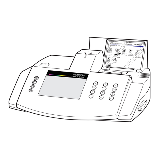
- Page 39 1 Overview Description of the operating elements Display Function keys Recess for MemoChip Notch for cell alignment Round cell shaft Analysis specifications (short form) Cover with integrated on/off switch Rectangular cell shaft Keypad with softkeys Opening for Memory Card...
- Page 40 1 Overview Keys Function keys: Scroll key: Concentration measurement key: Select menu items, scroll Call up the concentration measurement mode Call up/Enter key: Call up menu items, confirm inputs, Absorbance/Transmission measure- start measuring, switch to the configu- ment key: ration menu from the measuring mode Call up the Absorbance/Transmission measuring mode Keypad:...
- Page 41 1 Overview Operation In this section, only the principles of the operation are explained. Please commission the photometer according to chapter before trying out the operation. OMMISSIONING 1.3.1 Selecting and calling up the menu items → Starting point: Concentration or Absorbance/ Transmission measuring mode.
- Page 42 1 Overview Selection lists: Changes to the settings are accepted after confir- mation by pressing Current settings are marked by " " Change to other configuration levels by – Selecting the menu item, return – Pressing Scroll/select by pressing Character input: →...
- Page 43 1 Overview 1.3.2 Actuating the softkeys At some function levels, function fields appear in the display with different functions and labels in each case. These fields are actuated by the adjacent key of the keypad, the so-called softkeys Sample displays: Softkeys to operate the function fields: The keys that have a function field next to them (in this example...
- Page 44 1 Overview Identifying the connectors Plug of the power supply unit Socket for the power supply unit RS 232 Serial interface Line adaptor Plug-in power supply unit...
- Page 45 2 Safety This operating manual contains basic instructions to working with the meter. be followed in the commissioning, operation and main- The operating manual must always be available in the tenance of the meter. Consequently, all responsible vicinity of the meter. personnel must read this operating manual before Target group The photometer was developed for use in the labora-...
- Page 46 2 Safety Warning Warning Observe the notes supplied with the re- Observe the regulations when dealing agents and accessories (safety instruc- with dangerous substances tions, protective measures, application, handling, disposal etc.)! Follow the operating instructions at the workplace Use only original spare parts. 2.3.1 Designation of notes Warning...
- Page 47 3 Commissioning The photometer is a sensitive measuring The photometer operates at an environ- instrument. Take this into consideration mental temperature of + 5 °C to + 35 °C. when choosing the surroundings. Espe- During transport from cold to warm sur- cially avoid vapors and gases that might roundings, condensation can form result- attack mechanical, optical and electroni-...
- Page 48 3 Commissioning → Connect the plug of the plug-in power supply unit supplied to the socket of the photometer → Plug the suitable adaptor onto the plug-in power supply unit . By pushing the adaptor upwards, it can be removed and replaced by a different one if necessary (see arrow) →...
- Page 49 3 Commissioning Switching on the photometer → To switch on the photometer, open the cover. → Insert the cards with the analysis specifications into the compartment in the cover. To do so, pull out the transparent lid, insert the cards and push the lid back again.
- Page 50 3 Commissioning During the measurement of the kinetic (see The AutoCheck function automatically 10.2 K section ), the photometer INETICS checks and calibrates the optical measur- cannot perform an AutoCheck due to the in- ing unit. To do this, the photometer per- serted cell.
- Page 51 4 Short manual The short manual lists all of the steps necessary to determine the concentration of a sample and to acti- vate AQA2 at a glance (AQA = Analytical Quality Assurance; AQA2 = Check of the entire system). → Put the photometer into operation (see chapter OMMISSIONING Measuring the concentration...
- Page 52 4 Short manual Checking the system (AQA2) → Place the AQA MemoChip in the recess on the photometer. The following display appears: The action of placing the AQA MemoChip in the re- cess directly activates the AQA check without having to press any key.
- Page 53 5 Measuring the concentration For photometrical concentration mea- Warning surements, it is always necessary to pre- It is essential to follow the safety instruc- pare the sample to be measured. tions and notes on protective measures Information on sample preparation can when handling chemicals, in order to be found in the first part, General infor- avoid damage to your health and the en-...
- Page 54 5 Measuring the concentration Measuring using reagent tests with AutoSelector → Insert the AutoSelector into the round cell shaft. AutoSelector The AutoSelector serves to transmit the code for the reagent test to the photometer. → Align the line mark to the notch of the photometer. Line mark Barcode The photometer reads the barcode and automatically...
- Page 55 5 Measuring the concentration If the select method menu appears, the pho- tometer has not yet recognized the barcode of the AutoSelector. Align the line mark of the AutoSelector to the notch of the photometer. After the measurement is finished: The measured value appears on the display.
- Page 56 5 Measuring the concentration → Enter the required method number via the numeric keypad (if a cell is inserted, the photometer only accepts those methods for input that are available for this cell type). → Select the method by scrolling with (if a cell is inserted, the photometer only offers those methods that are available for this cell type).
- Page 57 6 Measuring the absorbance/transmission Call up the Absorbance/Transmission measuring mode → Press Absorbance measurement To switch to the transmission measuring mode: → Press If a cell is left in the cell shaft while you switch between the absorbance and transmission measurement, you have to insert the cell once again to start the measurement.
- Page 58 6 Measuring the absorbance/transmission Measuring using coded cell tests → Insert the round cell with barcode into the round Line mark cell shaft until it clicks into place. → Align the line mark to the notch of the photometer. Barcode After the measurement is finished: The measured value for the wavelength displayed at the top right appears.
- Page 59 6 Measuring the absorbance/transmission Measuring using reagent tests with AutoSelector → First insert the AutoSelector into the round cell AutoSelector shaft. Line mark → Align the line mark to the notch of the photometer. Barcode → Then insert the rectangular cell into the rectangu- lar cell shaft.
- Page 60 6 Measuring the absorbance/transmission Measuring using tests without barcode Always measure using one cell only. The cell shaft which is not used has to be empty. → Insert the round cell or rectangular cell. The last wavelength selected manually appears on the display.
- Page 61 7 Documentation The measured values are documented as follows: Storage in the measured value memory (automatic) Output to a connected printer via the serial inter- face (automatic when a printer is connected) Transmission to a PC for further processing (by using the relevant software, e.
- Page 62 7 Documentation The numbering of the measured values begins at 000 again (default) Consecutive numbering of the measured values (from 000 to 999) → Select the menu item: Press → Confirm with Activating the ID number If the ID number function is active, a sequence of up to 6 alphanumeric characters (ID number) is allocated to a measurement (e.
- Page 63 7 Documentation Measuring using the activated "ID number" function → Call up the concentration measuring mode by pressing → Insert the round cell and align it. → Insert the AutoSelector and rectangular cell. The following display appears: → Input the required ID number Default: The ID number that was last entered (initially, it is underscores).
- Page 64 7 Documentation Download memory The measured value storage can be selectively down- loaded to either the display or serial interface. The selection of the output medium is made after the spec- ification of the sorting criteria. → Call up the download memory submenu. The download memory menu item only appears after at least one measurement has been performed.
- Page 65 7 Documentation Select the output medium: to display to printer/PC (serial interface). → Select a menu item using → Confirm with to start the memory download. Selecting with ID number Input the ID number → Input the method: The last ID number entered is preselected. →...
- Page 66 7 Documentation Selecting AQA → Input the method Default: The last method set up manually appears on the display. → Confirm with to start the memory download. Only values of AQA check measurements are output. Memory download to display Each data record appears individually on the display beginning with the data record just measured.
-
Page 67: Method Output To The Display
7 Documentation Output of the methods list The stored methods can be selectively downloaded to either the display or serial interface. The selection of the output medium is made after the selection all/user def. methods. → Call up the output methods submenu. The following parameters can be set: Output of all stored methods user def. -
Page 68: Method Output To The Printer/Pc
7 Documentation Method output to the printer/PC: Method output to the serial interface: Display of the transmitted method (continuation dis- play, e. g. the 14th one of 103 methods). → Cancel using Sample printout: 14542 - 18.0 mg/l NO3-N 525nm 25.05.99 14773 - 20.0... -
Page 69: Method Parameters
8 Method parameters The following parameters can be set in the method parameters submenu: Citation form Unit Dilution → Call up the setup menu. The following display appears: → Call up the method parameters submenu. → Scroll through the methods using or enter the method number via the numeric keypad →... -
Page 70: Citation Form
8 Method parameters Citation form 8.1.1 Changing the citation form Example: Change the citation form from "PO -P" to "P ". → Select the citation submenu. The current setting: PO -P ( → Using scroll to P → Confirm with The citation form is set to P... -
Page 71: Performing A Difference Measurement
8 Method parameters 8.1.2 Performing a difference measurement For some methods, it is possible to perform a differ- ence measurement (e. g. iron II/III, Ca/Mg hardness). Further information on this is given in the third part, Analytical procedures of this operating manual. - Page 72 8 Method parameters After the measurement is finished: The 1st measured value appears on the display. å Fe. → Remove cell 1 → Press → Start the 2nd measurement by inserting cell 2. After the measurement is finished: The 2nd measured value appears on the display. Fe II.
-
Page 73: Selecting The Unit
8 Method parameters Selecting the unit The preset unit is “mg/l”. This can be changed to “mmol/l”. → Call up the unit submenu. The current setting: mg/l ( → Using , scroll to mmol/l → Confirm with The unit is set to mmol/l ( Entering the dilution Diluting a sample with distilled water enables the mea- suring range to be extended. - Page 74 8 Method parameters → Input the dilution factor 19 via the numeric keypad → Confirm with → Call up the concentration measuring mode using → Insert the cell → Confirm the method. The measured value is displayed together with the di- lution factor.
-
Page 75: Analytical Quality Assurance
9 Analytical Quality Assurance (AQA) The analytical quality assurance (AQA) can be perfor- med in two steps: AQA1: monitoring of the photometer AQA2: monitoring of the total system (photometer, accessories and the operator's way of working) AQA1 photometer monitoring and AQA2 method-specific system monitoring are con- ducted completely separately in the pho- tometer. -
Page 76: Activating Aqa
9 Analytical Quality Assurance (AQA) Activating AQA 9.1.1 Activating AQA using the MemoChip AQA → Place the AQA MemoChip in the recess on the photometer. The following display appears: The action of placing the AQA MemoChip in the recess directly activates the AQA check without having to press any key. -
Page 77: Activating Aqa Via The Menu Guide
9 Analytical Quality Assurance (AQA) 9.1.2 Activating AQA via the menu guide → Call up the setup menu. → Call up the meter setup submenu. The meter setup submenu appears with the AQA con- figuration menu item preselected. → Confirm with A password request appears: A user-defined password protects the settings of the AQA configuration against unauthorized access... - Page 78 9 Analytical Quality Assurance (AQA) After the password has been successfully input, the AQA configuration submenu appears: → Call up the AQA mode function. Default: off (no monitoring) → Select the menu item, on, by pressing → Confirm with → return to the setup menu. →...
-
Page 79: Changing Aqa Intervals
9 Analytical Quality Assurance (AQA) 9.1.3 Changing AQA intervals The AQA intervals specify the time interval between two AQA checks. Two separate intervals can be set up for both photometer and system monitoring. After an interval has expired, the following conse- quences become effective: Warning and loss of AQA identification Locking of the method for concentration measure-... -
Page 80: Locking The System
9 Analytical Quality Assurance (AQA) 9.1.4 Locking the system The function system locked is effective if, for a moni- tored method, no AQA check was performed, The AQA check “system” has expired. As a result, a concentration measurement is not pos- sible for this method. -
Page 81: Performing An Aqa Reset
9 Analytical Quality Assurance (AQA) → Input the required password, e. g. 0100: – Numerals via the numeric keypad or using – Capital letters using – Confirm the input using → Input the password once again: → Confirm with 9.1.6 Performing an AQA reset If you want to reset the Analytical Quality Assurance to the delivery state, use the reset function in the AQA... -
Page 82: Photometer Monitoring (Aqa1)
9 Analytical Quality Assurance (AQA) Photometer monitoring (AQA1) 9.2.1 Entering PhotoCheck standards ® A Spectroquant PhotoCheck is required to per- form the photometer monitoring. The theoretical values (absorbances) of all 12 available stan- dards are already stored in the photometer. If these values differ from the theoretical values in ®... -
Page 83: Output Of Photocheck Standards
9 Analytical Quality Assurance (AQA) The value of the pre-stored standard appears on the display. → Input the new theoretical value 445-1 via the numeric keypad → Confirm with → Input the tolerance via the numeric keypad → Confirm with →... - Page 84 9 Analytical Quality Assurance (AQA) Example: Report output AQA check of meter AQA1 26.08.99 13:19 AQA interval 12 W. test solution Unit theor. value tolerance AQA date 445-1 0.200 0.020 26.08.99 445-2 0.500 0.030 26.08.99 445-3 1.000 0.040 26.08.99 445-4 1.500 0.050 26.08.99...
-
Page 85: Performing Photometer Monitoring
9 Analytical Quality Assurance (AQA) 9.2.3 Performing Photometer monitoring Photometer monitoring includes a check of the Light barriers using the L1/L2 cells (contained ® within the scope of delivery of the Spectroquant PhotoCheck) Absorbance measurement using PhotoCheck standards. ® When using a new Spektroquant PhotoCheck packet, check the theoretical values stored in the photometer and if necessary correct them... - Page 86 9 Analytical Quality Assurance (AQA) → Insert the L2 cell. After the measurement is finished: After successful light barrier testing, the PhotoCheck standards (test solutions) are measured. Example: → Insert a cell with the test solution, 445-1. The photometer measures the absorbance of the test solution and compares the result with the value en- tered.
- Page 87 9 Analytical Quality Assurance (AQA) After the measurement is finished: Absorbance test OK..or error message After approx. 3 s: After approx. 5 s: The last measurement is repeated. → Insert the next test solution Clearing the error: → Cancel: →...
- Page 88 9 Analytical Quality Assurance (AQA) Example: Report output AQA check of meter AQA1 26.08.99 10:23 Operator: AQA interval 12 W. AQA check of meter L check test solution Measured value Unit theor. value tolerance result 445-1 0.209 0.200 0.020 445-2 0488 0.500 0.030...
-
Page 89: Performing The Pipecheck
9 Analytical Quality Assurance (AQA) 9.2.4 Performing the PipeCheck The PipeCheck rapidly and easily determines any potential pipette errors. While doing so, the photome- ter identifies pipettes with volume errors of more than 5 % as faulty. A Spectroquant® PipeCheck is required to perform the PipeCheck. - Page 90 9 Analytical Quality Assurance (AQA) → Insert the test cell. If a test cell unsuitable for the reference cell is inserted, the meter does not accept it and still displays: insert test cell. PipeCheck OK ..or error message After approx. 5 s: →...
-
Page 91: Total System Monitoring (Aqa2)
9 Analytical Quality Assurance (AQA) Total system monitoring (AQA2) 9.3.1 Entering standards ® The standards compiled in the table “Spectroquant CombiCheck and standard solutions” (see part 1 General information of this operating manual) are already stored in the photometer. These values can be overwritten. - Page 92 9 Analytical Quality Assurance (AQA) Example: Method 14729 with a preset theoretical value of 15.0 mg/l and tolerance of 1.0 mg/l (CombiCheck 80). Change to: theoretical value = 8 mg/l, tolerance = 0.7 mg/l (CombiCheck 20). → Confirm with → Input the new theoretical value, e. g. 8.0 mg/l, via the numeric keypad.
-
Page 93: Output Of Standards
9 Analytical Quality Assurance (AQA) 9.3.2 Output of standards The current list of stored standards can be output via the RS 232 interface (PC/printer) or via the display. → Select the output submenu → Confirm with Select the output medium: to display to printer/PC (serial interface). -
Page 94: Erasing Standards
9 Analytical Quality Assurance (AQA) 9.3.3 Erasing standards Erasing the method-specific standard solutions leads to the change of the measured value identification from AQA2 to AQA1 (with activated AQA mode and successfully performed meter monitoring). → Call up the standard solutions submenu. →... -
Page 95: Performing Total System Monitoring
9 Analytical Quality Assurance (AQA) 9.3.4 Performing total system monitoring AQA entry Using AQA MemoChip..or via a menu → In the setup menu, call up the AQA check sub- menu. → Call up the system submenu. → Insert the AQA MemoChip. →... - Page 96 9 Analytical Quality Assurance (AQA) The AQA check system must be performed separately for each method monitored. The release is stored with the date and the "sys- tem” AQA interval set up for the respective method is restarted. Example: Report output AQA check of system AQA2 26.08.99...
-
Page 97: Special Functions
10 Special functions 10.1 Spectrum The spectrum function facilitates to measure the absorbance at several wavelengths simultaneously. The course of the absorbance is presented graphi- cally or in the form of a table in a selectable range within 330 nm to 850 nm (smallest range 10 nm). →... - Page 98 10 Special functions Example: Setting to manual scaling of the axes, changing the coordinate limits to the wavelength range 400 nm to 800 nm (default 330 nm to 850 nm) and absorbance range 0.000 A to 2.000 A (default 0.000 A to 2.500 A). graphic parameters submenu: →...
-
Page 99: Measuring The Spectrum
10 Special functions 10.1.2 Measuring the spectrum → In the spectrum menu, call up the measure spec- trum menu item. → Insert the cell or use to start the measure- ment. The message measuring ... appears. The spectrum for the selected method appears as a graphic with the specified parameters. - Page 100 10 Special functions The smallest possible zoom window is limit- ed to 10 nm in the x axis. The smallest adjustable distance in the y axis is 0.1 A (Absorbance) or 10% T (Transmis- sion), depending on the unit selected. The contents of the zoom window are displayed en- larged.
-
Page 101: Measuring The Baseline
10 Special functions 10.1.3 Measuring the baseline This function is used to newly determine the reference absorbance or transmission for a wavelength range. The baseline is stored and is used as a new reference value for the spectrum measurement. → Select the measure baseline function from the spectrum menu. -
Page 102: Kinetics
10 Special functions 10.2 Kinetics The kinetics function enables the tracking of time-de- minimum 1 minute, maximum 999 times the measur- pendent changes in concentration or absorbance by ing interval. The maximum number of measuring cy- repeat measurements. When doing this, the photome- cles of a kinetic measurement is 1000 measurements ter measures at an adjustable time interval (setting: (until the memory is full of kinetic measured values). -
Page 103: Setting The Kinetic Parameters
10 Special functions 10.2.1 Setting the kinetic parameters → Call up the menu item, kinetic parameters. → Input the measuring interval via the numeric key- pad (default: 10 sec). Possible settings: 00:10 to 10:00 → Confirm with → Input the measuring duration via the numeric key- pad (default: 1 min). - Page 104 10 Special functions Example: Setting a measuring interval of 10 s, measuring dura- tion 10 min, unit A, manual scaling of the y axis, absorbance range 0.000 A to 1.500 A (default 0.000 A to 2.500 A). kinetic parameters submenu: →...
-
Page 105: Measuring The Kinetics
10 Special functions 10.2.2 Measuring the kinetics → Call up the measure kinetics menu item in the cinetics menu. → Insert the cell or use to start the measure- ment. The message measuring ... appears. The sample warms up during kinetic mea- surements with long measuring durations. - Page 106 10 Special functions Graphical display of the kinetics The cursor keys are active: Pressing moves the cursor on the curve to the right or the left. key moves the cursor to the highest point of the curve. The key moves the cursor to the lowest point of the curve.
- Page 107 10 Special functions Tabular display of the kinetics → table: Press to display the kinetics as a table. The table lists the times of the kinetic measurements and the corresponding measured values. → Press to bring the maximum or mini- mum value into the upper line of the table →...
-
Page 108: Color
10 Special functions 10.3 Color The color function facilitates the convenient measure- ment of the color of a solution at three different wave- lengths (436 nm, 525 nm, 620 nm) at the same time, according to EN ISO 7887 of 1994. The photometer gives the result of the color measurement in m . -
Page 109: Correction Functions
11 Correction functions → In the setup menu, call up the meter setup sub- menu. The following display appears: Call up the correction funct. submenu. The following display appears: Select the correction function: blank value reference absorbance reference transmission turbidity correct. →... -
Page 110: Blank Value
11 Correction functions 11.1 Blank value The blank value (= reagent blank value) for each The measured blank value is stored until method is stored in the photometer. the photometer is switched off When the blank value function is active, the stored val- the method is changed ue is ignored and the measured value of a self-pre- it is manually erased using the erase blank value... - Page 111 11 Correction functions → Insert a cell with blank solution to start a mea- surement. The message measuring... appears on the dis- play. The measured blank value applies for all sub- sequent measurements using the identical method (the photometer only stores one sin- gle blank value each time for a whole series of measurements).
-
Page 112: Reference Absorbance
11 Correction functions 11.2 Reference absorbance Each absorbance measurement is made against the The measured reference absorbance value remains basic absorbance stored in the meter. stored until When measuring the reference absorbance, this value the photometer is switched off is ignored and the value measured as the reference the cell type (10mm, 20mm, 50mm, round) is absorbance is used instead. - Page 113 11 Correction functions → Insert the cell to start a measurement. The message measuring... appears on the dis- play. After the measurement is finished: The measured value for the wavelength displayed at the top right appears. → Call up the absorbance measuring mode by pressing →...
-
Page 114: Reference Transmission
11 Correction functions 11.3 Reference transmission Each transmission measurement is made against the The measured reference transmission value remains basic transmission stored in the meter. stored until When measuring the reference transmission, this val- the photometer is switched off ue is ignored and the value measured as the reference the cell type (10 mm, 20 mm, 50 mm, round) is transmission is used instead. - Page 115 11 Correction functions → Insert the cell to start a measurement. The message measuring... appears on the dis- play. After the measurement is finished: The transmission value for the wavelength displayed at the top right appears. → Call up the absorbance/transmission measuring mode by pressing →...
-
Page 116: Turbidity Correction
11 Correction functions 11.4 Turbidity correction Turbidity correction is used in sample solutions that The turbidity correction function is not active when de- contain finely distributed suspended particles. livered. The suspended particles cause a light absorption. This leads to incorrect (too high) measured values. This function is not necessary, or useful, in all methods. -
Page 117: Zero Adjustment
12 Zero adjustment Zero adjustment is necessary after changing the lamp after the error message PhotoCheck occurs (AQA1) after changing the Memory Card on initial commissioning if the photometer was mechanically stressed, e.g. percussion, transport if the ambient temperature changed by more than 5 °C since the last zero adjustment at least every six months. - Page 118 12 Zero adjustment → In the setup menu, call up the meter setup sub- menu. → The following display appears: → Call up the zero adjustment submenu. → Insert a cell with distilled water. The message measuring... appears on the dis- play.
-
Page 119: User-Defined Methods
13 User-defined methods User-defined methods can be stored under code num- you can modify them. If the input is successful, the me- bers. Numbers from 301 to 399 are allowed. These ter displays the accepted method. code numbers are used to fast-find user-defined me- thods when setting methods. -
Page 120: Entering Characteristics Via The Keyboard
13 User-defined methods 13.1 Entering characteristics via the keyboard → Call up the input charact. submenu. → Input the method number (301 to 399) via the numeric keypad → Confirm with Confirming without entering a character terminates the input for the current field; continues with the next field. - Page 121 13 User-defined methods At this point, the photometer provides practical default values for the AQA theoretical value and tolerance. They can be overwritten using the numeric keypad. → Confirm each time using → Use to select between input zero point and slope calculate zero point and slope.
- Page 122 13 User-defined methods → To measure the absorbance, insert a cell (without barcode) with standard solution → Input the absorbance via the numeric keypad. The absorbance value of the first standard solution appears on the display. → Remove the cell →...
- Page 123 13 User-defined methods Sample printout: 27:05:99 11:33:09 TEST1 c [mg/l] A (585 nm) 0.137 0.214 0.290 0.369 0.445 zero point: 0.090 slope (A/c): 0.000496 corr. coefficient: 0.997 Graphical display of the characteristics graphic: Pressing displays the characteristics of the user-defined method graphically. The graphic shows the course of the absorbance in the defined measuring range.
- Page 124 13 User-defined methods Storing the characteristics: Starting point: table: → Storing the characteristics: return: Pressing displays the code number and characteristics as a list. → Terminating without storing: to switch to the measuring mode. → Scroll using → To store the new method and return, press The method data is automatically printed.
-
Page 125: Entering Characteristics Via The Pc
13 User-defined methods 13.2 Entering characteristics via the PC Data format of the method data: The data of user-defined methods is transferred in a string. The individual datablocks of the string are sep- arated by spaces: Further information is given in the chapter 16 RS 232 C INTERFACE Datablock... -
Page 126: Printing Characteristics
13 User-defined methods 13.3 Printing characteristics → Call up the print charact. submenu. → Start printing using The characteristics of all user-defined methods are printed sequentially as a list. → Cancel using Example: Report printout Date Time user-def. methods: code no. designation TEST1 wavelength... -
Page 127: Erasing User-Defined Methods
13 User-defined methods 13.4 Erasing user-defined methods → Call up the delete charact. submenu. Select the required menu item: Erase all user-defined methods single Selectively erase individual methods → Confirm with Selecting single Example: Erase TEST1 → Select the method, e. g. TEST1: –... - Page 128 13 User-defined methods...
-
Page 129: Photometer Setup
14 Photometer setup → In the setup menu, call up the meter setup sub- menu. The following display appears: This chapter describes four functions of the meter set- up menu: select language set date/time reset system info 14.1 Selecting the language The following languages are stored in the photometer: German Polish... -
Page 130: Setting Up The Date And Time
14 Photometer setup 14.2 Setting up the date and time → Call up the set date/time menu item. → Input the date via the numeric keypad → Confirm with → Input the time via the numeric keypad → Confirm with 14.3 Performing a meter reset It is possible to reset the photometer to its factory set-... -
Page 131: System Information
14 Photometer setup Example: Performing a total reset → Select the reset menu item → Confirm with A meter reset is performed (measured value store and setup). 14.4 System information → Call up the system info menu item. Sample display... - Page 132 14 Photometer setup...
-
Page 133: Updating Method Data
15 Updating method data 15.1 Downloading and updating method data from the Internet In the Internet, you will always find the latest method following: data for your photometer. A method update contains PC (Win 95 or higher) with Internet connection all new test sets and methods respectively. - Page 134 15 Updating method data During the download, the following display appears on the photometer screen: Test mode Remote → After the download, confirm the "Data successfully downloaded" message. The download is finished. The photometer returns to the Concentration measuring mode. You can check whether the new method data are stored in the photometer.
-
Page 135: Update Method Data Via The Memochip
15 Updating method data 15.2 Update method data via the MemoChip Modified or new data of individual methods can also be updated by means of a MemoChip. The method data is read in after initializing the photo- meter by switching it on (opening the cover) with the MemoChip in place (recess in the housing front, with the printing of the MemoChip facing upwards). - Page 136 15 Updating method data If a version of the method is already stored in the photometer, a message appears together with the dates of both versions: → Press to stop the data transfer. The 15 minu- tes warm-up period of the photometer begins then.
-
Page 137: Rs 232 C Interface
16 RS 232 C interface Via the interface, data can be output to a printer and exchanged with a personal computer (PC) To transmit data quickly and conveniently, the following accessories are available (with operating manuals): Printer cable Printer Interface cable Communication software. -
Page 138: Output Format Of Measured Values
16 RS 232 C interface Command Function CSPK [Lmin Lmax] Measurement and transmission of all measured values of the spectrum [Lmin Lmax] = wavelength range CEME 13 U Input user-defined methods (see chapter DEFINED METHODS REME [MMM] Output user-defined methods [MMM] = method number CCLR [MMM] Erase user-defined methods... -
Page 139: Data Transmission
16 RS 232 C interface 16.4 Data transmission Baud rate 4800 Data bits Stop bits Parity none Handshake Hardware Max. cable length 15 m 16.5 PIN allocation of the RS232 interface Photometer Computer Printer Allocation 9-pin socket 9-pin socket 25 pin plug with RS 232 C interface –... - Page 140 16 RS 232 C interface...
-
Page 141: Maintenance And Cleaning
17 Maintenance and cleaning The photometer is almost maintenance-free. The only maintenance task is replacing the lamp if it is defec- tive. A spare lamp is included in the scope of delivery of the photometer. 17.1 Changing the lamp → Switch off the photometer and disconnect it from the mains Warning Before starting to change the lamp,... -
Page 142: Actions To Take If A Cell Is Broken
17 Maintenance and cleaning → Set up the photometer again and connect it to the mains → Switch on the photometer (open the cover) → Perform a zero adjustment (see chapter 12 Z ADJUSTMENT 17.2 Actions to take if a cell is broken Caution Do not rotate the photometer to pour out the liquid! The liquid shall not come into... -
Page 143: Exchanging The Memory Card
18 Exchanging the Memory Card The Memory Card contains all data relevant for the operation of the photometer. The photometer software can be simply and easily updated by means of a Memory Card. → Switch off the photometer → Press the button at the right side of the photo- meter to throw out the old Memory Card →... - Page 144 18 Exchanging the Memory Card...
-
Page 145: Technical Data
19 Technical data Optical measuring principle Single beam spectrophotometer; Simultaneous recording of all wavelengths Light source Tungsten halogen lamp, premounted Operational lifetime: typical 500 operating hours Dispersion element Aberration-corrected concave lattice Receiver 256 x photo diode array Wavelength -range 330 nm to 850 nm ±... - Page 146 19 Technical data Meter safety EN 61010-1, IEC 1010 Safety class EN 61010-1 / class III Plug-in power supply unit Type Friwo FW7362/08,11.9833, Friwo Part-No. 1811504 Input: 100 – 240 V ∼ ± 10% / 50 – 60 Hz / 700 mA (installation category ll) Output: 7.5 VDC / 3.3 A alternatively:...
- Page 147 19 Technical data Software settings ID number input: Off when delivered Measured value number: 000 Blank value: Off Reference absorbance: Off Reference transmission: Off Turbidity correction: Off Language: English Kinetic interval: 60s Date of the last valid AQA1 check: invalid (not yet mea- sured) AQA1 interval: 12 weeks AQA2 interval: 4 weeks...
- Page 148 19 Technical data Settings after reset - AQA Date of the last valid AQA1 check: invalid (not yet mea- sured) AQA1 interval: 12 weeks AQA2 interval: 4 weeks AQA password: 0000 AQA mode: Off Lock measurement if AQA2 expired: Off AQA1 values: PhotoCheck standard 445-1...
-
Page 149: What To Do If
20 What to do if... Cause Remedy → Connect the photometer to the mains The display remains blank No power supply. when switched on supply via the plug-in power supply unit. → Send the meter to the service depart- Date/time is lost when swit- The support battery of the real ched off time clock is empty. - Page 150 20 What to do if... Error messages on the dis- Cause Remedy play: → Clean the cell shaft with a damp, lint- Remove cell The message remove cell ap- pears on the display although free cloth. → If the error message still appears, no cell is inserted.
-
Page 151: Appendix
21 Appendix This chapter offers additional information and orienta- tion aids. Menu structure The menu structure shows the structure of the setup menu and the submenus in an overview. Abbreviations The list of abbreviations explains display indications and abbreviations that occur when dealing with the measuring instrument. -
Page 152: Menu Structure Of The Setup Menu
21 Appendix 21.1 Menu structure of the setup menu... - Page 153 21 Appendix...
- Page 154 21 Appendix...
-
Page 155: List Of Abbreviations
21 Appendix 21.2 List of abbreviations Analytical Quality Assurance AQA1 Level 1 of the Analytical Quality Assurance: Photometer monitoring AQA2 Level 2 of the Analytical Quality Assurance: Total system monitoring auto automatic Absorbance abs. Absorbance L1 /L2 Cells to check the light barrier in the photometer L check Light barrier check in the photometer mg/l... -
Page 156: Glossary
21 Appendix 21.3 Glossary Absorbance Logarithmic dimension for the absorption of the sam- ple; negative decadic logarithm of the transmission Analytical Quality Assurance AQA I. D. Measured values are given an AQA I. D. (AQA1 or AQA2) in the documentation, depending on which AQA level was active when the measurement was per- formed AQA1... - Page 157 21 Appendix Recovery The recovery rate is the measured value found divided by the specified value (in percent). Example: Specified value 20 mg/l; measured value 19.7 mg/l => recovery 0.985 or recovery rate 98.5%. Reference absorbance With this function, the basic absorbance stored in the photometer can be replaced by an own measurement Reference transmission With this function, the basic transmission stored in the...
-
Page 158: Index
21 Appendix 21.4 Index Memory Card ......17 Memory of measured values ....34 Adaptor . - Page 159 21 Appendix User-defined methods ....89 Warm-up time ......19 Warranty .
- Page 162 Wissenschaftlich-Technische Werkstätten GmbH Dr.-Karl-Slevogt-Straße 1 D-82362 Weilheim Germany Tel: +49 (0) 881 183-0 +49 (0) 881 183-100 Fax: +49 (0) 881 183-420 E-Mail: Info@WTW.com Internet: http://www.WTW.com...
Need help?
Do you have a question about the PhotoLab Spektral and is the answer not in the manual?
Questions and answers