Table of Contents
Advertisement
Quick Links
D
G
S
-
7
0
8
4
D
G
S
-
7
0
8
4
I
n
d
u
s
t
r
i
a
l
M
a
I
n
d
u
s
t
r
i
a
l
M
E
t
h
E
t
h
U
s
e
U
s
G
C
P
-
A
I
O
_
S
G
C
P
-
A
I
O
_
S
n
a
g
e
d
G
i
g
a
a
n
a
g
e
d
G
i
g
a
e
r
n
e
t
S
w
i
t
c
e
r
n
e
t
S
w
i
t
c
r
'
s
M
a
n
u
e
r
'
s
M
a
n
u
V
e
r
s
i
o
n
2
.
0
V
e
r
s
i
o
n
2
.
0
D
e
c
,
2
0
1
2
D
e
c
,
2
0
1
2
S
E
R
I
E
S
S
E
R
I
E
S
b
i
t
B
y
p
a
s
s
b
i
t
B
y
p
a
s
s
h
h
a
l
a
l
w
w
w
.
o
r
i
n
g
-
n
e
t
w
w
w
.
o
r
i
n
g
-
n
e
t
w
o
r
k
i
n
g
.
c
o
m
w
o
r
k
i
n
g
.
c
o
m
Advertisement
Table of Contents

Related Manuals for ORiNG DGS-7084GCP-AIO_S SERIES


Summary of Contents for ORiNG DGS-7084GCP-AIO_S SERIES
- Page 1 ’ ’...
- Page 2 ORing warrants that all ORing products are free from defects in material and workmanship for a specified warranty period from the invoice date (5 years for most products). ORing will repair or replace products found by ORing to be defective within this warranty period, with shipment expenses apportioned by ORing and the distributor.
-
Page 3: Table Of Contents
DGS-7084GCP-AIO_S SERIES User’s Manual Table of Content Getting to Know Your Switch ............... 5 About the DGS-7084GCP-AIO_S Industrial Switch ............5 Software Features ......................6 Hardware Features ......................7 Hardware Overview ................8 ... - Page 4 DGS-7084GCP-AIO_S SERIES User’s Manual 4.1.4.3 Port Trunk ......................31 4.1.4.4 Loop Guard ......................37 4.1.5 Redundancy ........................37 4.1.5.1 O-Ring ......................... 37 4.1.5.2 O-Chain ....................... 38 4.1.5.3 MSTP ........................40 ...
- Page 5 DGS-7084GCP-AIO_S SERIES User’s Manual 4.1.12.4 System Log Information ................119 4.1.12.5 Cable Diagnostics ..................120 4.1.12.6 SFP Monitor ..................... 121 4.1.12.7 Ping ........................121 4.1.12.8 IPv6 Ping ......................122 ...
-
Page 6: Getting To Know Your Switch
DOS/DDOS auto prevention. If there is any IP flow become big in short time, ORing’s thunder switch will lock the source IP address for certain time to prevent the attack. It’s hardware based prevention so it can prevent DDOS attack without using CPU resource. -
Page 7: Software Features
DGS-7084GCP-AIO_S SERIES User’s Manual 1.2 Software Features Support 8xgigabit combo ports Support 4x1000Base- X SFP ports Support Jumbo frame up to 9.6K Bytes Supports O-Ring (recovery time < 30ms over 250 units of connection), MSTP/RSTP/STP (IEEE 802.1s/w/D) for Ethernet Redundancy ... -
Page 8: Hardware Features
DGS-7084GCP-AIO_S SERIES User’s Manual 1.3 Hardware Features One 100~240VAC power input for DGS-7084GCP-AIO_S Operating Temperature: -40 to 70 Storage Temperature: -40 to 85 Operating Humidity: 5% to 95%, non-condensing Casing: IP-30 8 x Gigabit combo ports and 4 x 1000 Base-X SFP ports ... -
Page 9: Hardware Overview
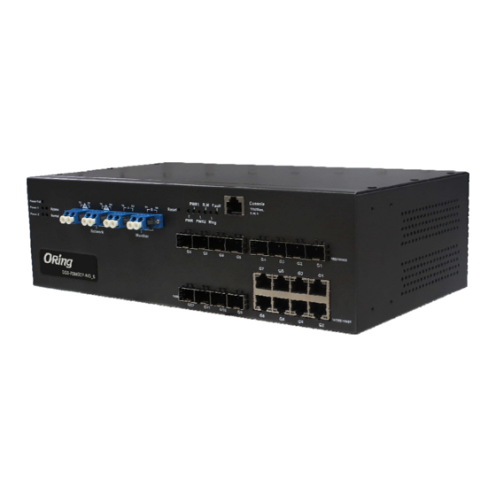
DGS-7084GCP-AIO_S SERIES User’s Manual ardware Overview 2.1 Front Panel The following table describes the labels that stick on the DGS-7084GCP-AIO_S Port Description 4 1000Base-X on SFP port Gigabit SFP ports Gigabit Combo 10/100/1000Base-T(X) RJ-45 + 100/1000Base-X SFP Ports Ports Use RS-232 with DB9 connecter to manage switch. -
Page 10: Back Panel
DGS-7084GCP-AIO_S SERIES User’s Manual 7. Ggiabit Combo Port with 10/100/1000Base-T(X) 8. LED for Ethernet ports Link/Act indicator 9. LED for Ethernet ports duplex/collision indicator 10. 1000Base-X SFP Port 11. LED for SFP ports link status. 2.2 Back Panel The back panel of DGS-7084GCP-AIO_S is shown as below: 1. - Page 11 DGS-7084GCP-AIO_S SERIES User’s Manual ORing Industrial Networking Corp...
-
Page 12: Front Panel Leds
DGS-7084GCP-AIO_S SERIES User’s Manual 2.4 Front Panel LEDs Bypass LED indicator: Color Status Description When the power module is in PWR UP state, the green LED Power Green lights on. When the power fail, the Power Fail Amber amber led will be light on. - Page 13 DGS-7084GCP-AIO_S SERIES User’s Manual Port link up. LINK/ACT Green Blinking Data transmitted ORing Industrial Networking Corp...
-
Page 14: Cables
DGS-7084GCP-AIO_S SERIES User’s Manual ables 3.1 Ethernet Cables The DGS-7084GCP-AIO_S switch has standard Ethernet ports. According to the link type, the switch use CAT 3, 4, 5,5e UTP cables to connect to any other network device (PCs, servers, switches, routers, or hubs). Please refer to the following table for cable specifications. -
Page 15: Sfp
DGS-7084GCP-AIO_S SERIES User’s Manual BI_DB+ BI_DA+ BI_DC+ BI_DD+ BI_DC- BI_DD- BI_DB- BI_DA- BI_DD+ BI_DC+ BI_DD- BI_DC- Note: “+” and “-” signs represent the polarity of the wires that make up each wire pair. 3.2 SFP The Switch has fiber optical ports with SFP connectors. The fiber optical ports are in multi-mode (0 to 550M, 850 nm with 50/125 µm, 62.5/125 µm fiber) and single-mode with LC... -
Page 16: Web Management
DGS-7084GCP-AIO_S SERIES User’s Manual EB Management 4.1 Configuration by Web Browser This section introduces the configuration by Web browser. 4.1.1 About Web-based Management An embedded HTML web site resides in flash memory on the CPU board. It contains advanced management features and allows you to manage the switch from anywhere on the network through a standard web browser such as Microsoft Internet Explorer. - Page 17 DGS-7084GCP-AIO_S SERIES User’s Manual The login screen appears. Key in the username and password. The default username and password is “admin”. Click “Enter” or ”OK” button, then the main interface of the Web-based management appears. Login screen Main Interface Main interface...
-
Page 18: Basic Setting
DGS-7084GCP-AIO_S SERIES User’s Manual 4.1.2 Basic Setting System Information 4.1.2.1 The switch system information is provided here. System Information interface Label Description The textual identification of the contact person for this managed node, together with information on how to contact this person. -
Page 19: Admin & Password
DGS-7084GCP-AIO_S SERIES User’s Manual Admin & Password 4.1.2.2 This page allows you to configure the system password required to access the web pages or log in from CLI. Label Description Old Password Enter the current system password. If this is incorrect, the new password will not be set. -
Page 20: Ip Setting
DGS-7084GCP-AIO_S SERIES User’s Manual IP Setting 4.1.2.3 Configure the switch-managed IP information on this page. Label Description DHCP Client Enable the DHCP client by checking this box. If DHCP fails and the configured IP address is zero, DHCP will retry. If DHCP fails and the configured IP address is non-zero, DHCP will stop and the configured IP settings will be used. -
Page 21: Ipv6 Configuration
DGS-7084GCP-AIO_S SERIES User’s Manual Click to undo any changes made locally and revert to previously saved values. Click to renew DHCP. This button is only available if DHCP is enabled. IPv6 Configuration 4.1.2.4 Configure the switch-managed IPv6 information on this page. -
Page 22: Https
DGS-7084GCP-AIO_S SERIES User’s Manual multiple 16-bit groups of contiguous zeros; but it can only appear once. It also used a following legally IPv4 address. For example, '::192.1.2.34'. SNTP Server Provide the IPv6 SNTP Server address of this switch. IPv6 address is in 128-bit records represented as eight fields of up to four hexadecimal digits with a colon separates each field (:). -
Page 23: Ssh
DGS-7084GCP-AIO_S SERIES User’s Manual 4.1.2.6 Label Description Indicates the SSH mode operation. Possible modes are: Mode Enabled: Enable SSH mode operation. Disabled: Disable SSH mode operation. Click to save changes. Click to undo any changes made locally and revert to previously saved values. - Page 24 DGS-7084GCP-AIO_S SERIES User’s Manual Rx only The switch will not send out LLDP information, but LLDP information from neighbor units is analyzed. Tx only The switch will drop LLDP information received from neighbors, but will send out LLDP information. Disabled The switch will not send out LLDP information, and will drop LLDP information received from neighbors.
- Page 25 DGS-7084GCP-AIO_S SERIES User’s Manual 7. DOCSIS cable device 8. Station only 9. Reserved When a capability is enabled, the capability is followed by (+). If the capability is disabled, the capability is followed by (-). Management Address is the neighbor unit's address that is used...
- Page 26 DGS-7084GCP-AIO_S SERIES User’s Manual Total Neighbors Shows the number of new entries deleted since switch reboot. Entries Deleted Total Neighbors Shows the number of LLDP frames dropped due to that the entry Entries Dropped table was full. Shows the number of entries deleted due to Time-To-Live Total Neighbors expiring.
-
Page 27: Backup/Restore Configuration
DGS-7084GCP-AIO_S SERIES User’s Manual regular intervals. Backup/Restore Configuration 4.1.2.8 You can save/view or load the switch configuration. The configuration file is in XML format with a hierarchy of tags: Firmware Update 4.1.2.9 This page facilitates an update of the firmware controlling the stack. switch. -
Page 28: Dhcp Server
DGS-7084GCP-AIO_S SERIES User’s Manual 4.1.3 DHCP Server 4.1.3.1 Setting The system provides with DHCP server function. Enable the DHCP server function, the switch system will be a DHCP server. 4.1.3.2 DHCP Dynamic Client List When the DHCP server function is activated, the system will collect the DHCP client information and display in here. -
Page 29: Dhcp Client List
DGS-7084GCP-AIO_S SERIES User’s Manual 4.1.3.3 DHCP Client List You can assign the specific IP address which is in the assigned dynamic IP range to the specific port. When the device is connecting to the port and asks for dynamic IP assigning, the system will assign the IP address that has been assigned before in the connected device. - Page 30 DGS-7084GCP-AIO_S SERIES User’s Manual Select any available link speed for the given switch port. Configured Link Auto Speed selects the highest speed that is compatible with a Speed link partner. Disabled disables the switch port operation. When Auto Speed is selected for a port, this section indicates the flow control capability that is advertised to the link partner.
-
Page 31: Rate Limit
DGS-7084GCP-AIO_S SERIES User’s Manual 4.1.4.2 Rate Limit Configure the switch port rate limit for Policers and Shapers on this page. Label Description Port The logical port for the settings contained in the same row. Policer Enabled Enable or disable the port policer. The default value is "Disabled". -
Page 32: Port Trunk
DGS-7084GCP-AIO_S SERIES User’s Manual Click to undo any changes made locally and revert to previously saved values. 4.1.4.3 Port Trunk 4.1.4.3.1 Trunk Configuration This page is used to configure the Aggregation hash mode and the aggregation group. Label Description Source MAC Address The Source MAC address can be used to calculate the destination port for the frame. - Page 33 DGS-7084GCP-AIO_S SERIES User’s Manual Label Description Group ID Indicates the group ID for the settings contained in the same row. Group ID "Normal" indicates there is no aggregation. Only one group ID is valid per port. Each switch port is listed for each group ID. Select a radio button...
- Page 34 DGS-7084GCP-AIO_S SERIES User’s Manual 4.1.4.3.2 LACP Port Configuration This page allows the user to inspect the current LACP port configurations, and possibly change them as well. Label Description Indicates the group ID for the settings contained in the same row.
- Page 35 DGS-7084GCP-AIO_S SERIES User’s Manual LACP packets each second; while Passive will wait for a LACP packet from a partner (speak if spoken to). Click to save changes. Click to undo any changes made locally and revert to previously saved values.
- Page 36 DGS-7084GCP-AIO_S SERIES User’s Manual 4.1.4.3.4 LACP Status This page provides a status overview for LACP status for all ports. Label Description The switch port number. Port LACP 'Yes' means that LACP is enabled and the port link is up. 'No' means that LACP is not enabled or that the port link is down.
- Page 37 DGS-7084GCP-AIO_S SERIES User’s Manual 4.1.4.3.5 LACP Statistics This page provides an overview for LACP statistics for all ports. Label Description The switch port number Port Shows how many LACP frames have been sent from each port LACP Transmitted Shows how many LACP frames have been received at each port.
-
Page 38: Loop Guard
DGS-7084GCP-AIO_S SERIES User’s Manual 4.1.4.4 Loop Guard Loop Guard is a looping detection/avoid strategy, it helps network administrator to avoid looping issue. Label Description Active Enable Loop Guard function. Guarding:This port is protected against looping. Port State Locked:This port has been locked to avoid looping. -
Page 39: O-Chain
DGS-7084GCP-AIO_S SERIES User’s Manual The following table describes the labels in this screen. Label Description Mark to enable Ring. Redundant Ring There should be one and only one Ring Master in a ring. However if there are two or more switches which set Ring... - Page 40 DGS-7084GCP-AIO_S SERIES User’s Manual Label Description Enable Enabling the O-Chain function Ring Port Choosing the port which connect to the ring Ring Port Choosing the port which connect to the ring Edge Port In the O-Chain application, the head and tail of two Switch Port, must start the Edge, MAC smaller Switch, Edge port will be the backup and RM LED Light.
-
Page 41: Mstp
DGS-7084GCP-AIO_S SERIES User’s Manual 4.1.5.3 MSTP Bridge Settings This page allows you to configure RSTP system settings. The settings are used by all RSTP Bridge instances in the Switch Stack. Label Description The STP protocol version setting. Valid values are STP, RSTP Protocol Version and MSTP. - Page 42 DGS-7084GCP-AIO_S SERIES User’s Manual MSTI Mapping This page allows the user to inspect the current STP MSTI bridge instance priority configurations, and possibly change them as well. Label Description The name identifying the VLAN to MSTI mapping. Bridges must share the name and revision (see below), as well as the...
- Page 43 DGS-7084GCP-AIO_S SERIES User’s Manual Click to save changes. Click to undo any changes made locally and revert to previously saved values. MSTI Priorities This page allows the user to inspect the current STP MSTI bridge instance priority configurations, and possibly change them as well.
- Page 44 DGS-7084GCP-AIO_S SERIES User’s Manual CIST Ports This page allows the user to inspect the current STP CIST port configurations, and possibly change them as well. This page contains settings for physical and aggregated ports. The aggregation settings are stack global.
- Page 45 DGS-7084GCP-AIO_S SERIES User’s Manual CIST or any MSTI, even if it has the best spanning tree priority vector. Such a port will be selected as an Alternate Port after the Root Port has been selected. If set, it can cause lack of spanning tree connectivity.
- Page 46 DGS-7084GCP-AIO_S SERIES User’s Manual Label Description The switch port number of the corresponding STP CIST (and Port MSTI) port. Controls the path cost incurred by the port. The Auto setting will set the path cost as appropriate by the physical link speed, using the 802.1D recommended values.
- Page 47 DGS-7084GCP-AIO_S SERIES User’s Manual STP Bridges This page provides a status overview for all STP bridge instances. The displayed table contains a row for each STP bridge instance, where the column displays the following information: Label Description The Bridge Instance. This is also a link to the STP Detailed Bridge MSTI Status.
- Page 48 DGS-7084GCP-AIO_S SERIES User’s Manual Label Description Port The switch port number of the logical STP port. The current STP port role of the CIST port. The port role can be CIST Role one of the following values: AlternatePort BackupPort RootPort DesignatedPort.
-
Page 49: Fast Recovery Mode
DGS-7084GCP-AIO_S SERIES User’s Manual Label Description Port The switch port number of the logical RSTP port. The number of RSTP Configuration BPDU's received/transmitted RSTP on the port. number legacy Configuration BPDU's received/transmitted on the port. The number of (legacy) Topology Change Notification BPDU's received/transmitted on the port. -
Page 50: Vlan
DGS-7084GCP-AIO_S SERIES User’s Manual The following table describes the labels in this screen. Label Description Active Activate the fast recovery mode. port Port can be configured as 12 priorities. Only the port with highest priority will be the active port. 1st Priority is the highest. - Page 51 DGS-7084GCP-AIO_S SERIES User’s Manual click on "Save". The VLAN is thereafter present on the other stack switch units, but with no port members. A VLAN without any port members on any stack unit will be deleted when you click "Save".
- Page 52 DGS-7084GCP-AIO_S SERIES User’s Manual 3. VLAN Port 1 Configuration-->Mode=specific,ID=50 (For egress port) 1. VLAN Membership Configuration setting port 2 & VID=50 2. VLAN Port 2 Configuration-->don't care VLAN Aware ORing Industrial Networking Corp...
- Page 53 DGS-7084GCP-AIO_S SERIES User’s Manual 3. VLAN Port 2 Configuration-->Mode=specific,ID=50 (any packet can enter egress port ) 802.1Q Access port Setting (For ingress port) 1. VLAN Membership Configuration setting port & VID=50 2. VLAN Port Configuration-->Enable VLAN Aware ORing Industrial Networking Corp...
- Page 54 DGS-7084GCP-AIO_S SERIES User’s Manual 1. VLAN Port Configuration-->Mode=specific,ID=50 (For egress port) 1. VLAN Membership Configuration setting port & VID=50 2. VLAN Port Configuration-->Disable VLAN Aware 3. VLAN Port Configuration-->Mode=specific,ID=50 (untagged & tag=50 packet can enter egress port ) ORing Industrial Networking Corp...
- Page 55 DGS-7084GCP-AIO_S SERIES User’s Manual 802.1Q Trunk port setting (multi-tag) (For ingress port) 1. VLAN Membership Configuration setting port & VID=11,22,33 ORing Industrial Networking Corp...
- Page 56 DGS-7084GCP-AIO_S SERIES User’s Manual 2. VLAN Port Configuration-->Enable VLAN Aware 3. VLAN Port Configuration-->Mode=specific,ID=11 (when entering packet is untagged frame, added tag = 11 When entering the tagged frame, only VID = 11,22,33 three kinds of packets can pass) ORing Industrial Networking Corp...
- Page 57 DGS-7084GCP-AIO_S SERIES User’s Manual (For egress port) 1. VLAN Membership Configuration setting port, VID=11,22,33 2. VLAN Port Configuration-->Enable VLAN Aware ORing Industrial Networking Corp...
- Page 58 DGS-7084GCP-AIO_S SERIES User’s Manual 3. VLAN Port Configuration-->Mode=none (egress port can receive tag=11,22,33 packet In addition ,ony tag=11packet can enter egress port ) QinQ VLAN Setting ingress Port 1------------------->egress Port 2 ORing Industrial Networking Corp...
- Page 59 DGS-7084GCP-AIO_S SERIES User’s Manual (For ingress port-----Port 1) 1. VLAN Membership Configuration setting port 1、2、3 & VID=50 2. VLAN Port Configuration-->Disable Port 1 VLAN Aware 3. VLAN Port Configuration-->Port 1 Mode=specific,ID=50 ORing Industrial Networking Corp...
- Page 60 DGS-7084GCP-AIO_S SERIES User’s Manual (For egress port ----Port 2) 1. VLAN Membership Configuration setting port & VID=50 2. VLAN Port Configuration-->Enable Port 2、3 VLAN Aware. 3. VLAN Port Configuration-->Mode=none (only tag=50 packet can enter egress port ) ORing Industrial Networking Corp...
-
Page 61: Private Vlan
DGS-7084GCP-AIO_S SERIES User’s Manual 4.1.6.2 Private VLAN The Private VLAN membership configurations for the switch can be monitored and modified here. Private VLANs can be added or deleted here. Port members of each Private VLAN can be added or removed here. Private VLANs are based on the source port mask, and there are no connections to VLANs. -
Page 62: Snmp
DGS-7084GCP-AIO_S SERIES User’s Manual The Private VLAN is enabled when you click "Save". button can be used to undo the addition of new Private VLANs. Label Description A check box is provided for each port of a private VLAN. When checked, port isolation is enabled for that port. - Page 63 DGS-7084GCP-AIO_S SERIES User’s Manual Label Description Indicates the SNMP mode operation. Possible modes are: Mode Enabled: Enable SNMP mode operation. Disabled: Disable SNMP mode operation. Indicates the SNMP supported version. Possible versions are: SNMP v1: Set SNMP supported version 1.
- Page 64 DGS-7084GCP-AIO_S SERIES User’s Manual Label Description Indicates the SNMP trap mode operation. Possible modes are: Trap Mode Enabled: Enable SNMP trap mode operation. Disabled: Disable SNMP trap mode operation. Indicates the SNMP trap supported version. Possible versions are: SNMP v1: Set SNMP trap supported version 1.
-
Page 65: Snmp-Communities
DGS-7084GCP-AIO_S SERIES User’s Manual Security Engine ID Possible values are: Enabled: Enable SNMP trap probe security engine ID mode of operation. Disabled: Disable SNMP trap probe security engine ID mode of operation. Indicates the SNMP trap security engine ID. SNMPv3 sends traps and informs using USM for authentication and privacy. -
Page 66: Snmp-Users
DGS-7084GCP-AIO_S SERIES User’s Manual 4.1.7.3 SNMP-Users Configure SNMPv3 users table on this page. The entry index keys are Engine ID and User Name. Label Description Delete Check to delete the entry. It will be deleted during the next save. An octet string identifying the engine ID that this entry should belong to. -
Page 67: Snmp-Groups
DGS-7084GCP-AIO_S SERIES User’s Manual MD5: An optional flag to indicate that this user using MD5 authentication protocol. SHA: An optional flag to indicate that this user using SHA authentication protocol. The value of security level cannot be modified if entry already exists. -
Page 68: Snmp-Views
DGS-7084GCP-AIO_S SERIES User’s Manual usm: User-based Security Model (USM). A string identifying the security name that this entry should belong to. Security Name The allowed string length is 1 to 32, and the allowed content is the ASCII characters from 33 to 126. -
Page 69: Snmp-Accesses
DGS-7084GCP-AIO_S SERIES User’s Manual 4.1.7.6 SNMP-Accesses Configure SNMPv3 accesses table on this page. The entry index keys are Group Name, Security Model and Security Level. Label Description Delete Check to delete the entry. It will be deleted during the next save. -
Page 70: Traffic Prioritization
DGS-7084GCP-AIO_S SERIES User’s Manual 4.1.8 Traffic Prioritization 4.1.8.1 Storm Control There is a unicast storm rate control, multicast storm rate control, and a broadcast storm rate control. These only affect flooded frames, i.e. frames with a (VLAN ID, DMAC) pair not present on the MAC Address table. -
Page 71: Port Qos
DGS-7084GCP-AIO_S SERIES User’s Manual 4.1.8.2 Port QoS This page allows you to configure QoS settings for each port. Frames can be classified by 4 different QoS classes: Low, Normal, Medium, and High. The classification is controlled by a QCL that is assigned to each port. -
Page 72: Qos Control List
DGS-7084GCP-AIO_S SERIES User’s Manual Queuing Mode Select which Queuing mode for this port. Setting Queue weighted (Low=Normal, Medium=High) if the Queue Weighted "Queuing Mode" is "Weighted". 4.1.8.3 QoS Control List This page lists the QCEs for a given QCL. Frames can be classified by 4 different QoS classes: Low, Normal, Medium, and High. -
Page 73: Queuing Counters
DGS-7084GCP-AIO_S SERIES User’s Manual DSCP: IPv4 and IPv6 DSCP. ToS: The 3 precedence bit in the ToS byte of the IPv4/IPv6 header (also known as DS field). Tag Priority: User Priority. Only applicable if the frame is VLAN tagged or priority tagged. -
Page 74: Wizard
DGS-7084GCP-AIO_S SERIES User’s Manual priority than the "Normal Queue". High Queue This is the highest priority queue of the 4 QoS queues. Receive / Transmit The number of received and transmitted packets per port. 4.1.8.5 Wizard This handy wizard helps you set up a QCL quickly. -
Page 75: Multicast
DGS-7084GCP-AIO_S SERIES User’s Manual 4.1.9 Multicast 4.1.9.1 IGMP Snooping This page provides IGMP Snooping related configuration. Label Description Snooping Enabled Enable the Global IGMP Snooping. Unregistered Enable unregistered IPMC traffic flooding. IPMC Flooding enabled VLAN ID The VLAN ID of the entry. -
Page 76: Igmp Snooping Status
DGS-7084GCP-AIO_S SERIES User’s Manual 4.1.9.2 IGMP Snooping Status Label Description VLAN ID The VLAN ID of the entry. Groups The present IGMP groups. Max. are 128 groups for each VLAN. Port Members The ports that are members of the entry. -
Page 77: Security
DGS-7084GCP-AIO_S SERIES User’s Manual 4.1.10 Security 4.1.10.1 Remote Control Security Configuration Remote Control Security allows you limit the remote access of management interface. When enabled, the request of client which is not in the allow list will be rejected. Label... - Page 78 DGS-7084GCP-AIO_S SERIES User’s Manual Label Description Indicates the per-port Device Binding operation. Possible modes are: ---: Disable. Scan: Scan IP/MAC automatically, but no binding function. Mode Binding: Enable binding function. Under this mode, any IP/MAC doesn't match the entry will not be allowed to access the network.
- Page 79 DGS-7084GCP-AIO_S SERIES User’s Manual 4.1.10.2.1 Advanced Configuration Alias IP Address This page provides Alias IP Address related configuration. Some device might have more IP addresses than one, you could specify the other IP address here. Label Description Specify Alias IP address. Keeps "0.0.0.0", if the device doesn't have Alias IP Address alias IP address.
- Page 80 DGS-7084GCP-AIO_S SERIES User’s Manual Alive Check Using the ping command, check port link status, if port link fail, user can setting action field, select the switch action. Label Description Disable and enable port. Link Change Only sent log to log server.
- Page 81 DGS-7084GCP-AIO_S SERIES User’s Manual Mode Enable/Disable DDOS Prevention of the port. Indicates the level of DDOS detection. Possible levels are: Low: Low sensibility. Sensibility Normal: Normal sensibility. Medium: Medium sensibility. High: High sensibility. Indicates the packet type of DDOS monitor. Possible types are: RX Total: Total ingress packets.
- Page 82 DGS-7084GCP-AIO_S SERIES User’s Manual This page provides Device Description related configuration Label Description Indicates the type of device. Possible types are: ---: No specification. IP Camera: IP Camera. IP Phone: IP Phone. Device Type Access Point: Access Point. PC: PC.
-
Page 83: Acl
DGS-7084GCP-AIO_S SERIES User’s Manual This page provides Stream Check related configuration. Label Description Enable/Disable stream monitor of the port. Mode Indicates the action when stream getting low. Possible actions are: Action ---: Do nothing. Log it: Just log the event 4.1.10.3 ACL... - Page 84 DGS-7084GCP-AIO_S SERIES User’s Manual Label Description Port The logical port for the settings contained in the same row. Select the policy to apply to this port. The allowed values are 1 Policy ID through 8. The default value is 1.
- Page 85 DGS-7084GCP-AIO_S SERIES User’s Manual Label Description Rate Limiter ID The rate limiter ID for the settings contained in the same row. The rate unit is packet per second (pps), configure the rate as 1, 2, 4, 8, 16, 32, 64, 128, 256, 512, 1K, 2K, 4K, 8K, 16K, 32K, 64K, 128K, Rate 256K, 512K, or 1024K.
- Page 86 DGS-7084GCP-AIO_S SERIES User’s Manual hexadecimal). ARP: Only ARP frames can match this ACE. Notice the ARP frames won't match the ACE with Ethernet type. IPv4: Only IPv4 frames can match this ACE. Notice the IPv4 frames won't match the ACE with Ethernet type.
- Page 87 DGS-7084GCP-AIO_S SERIES User’s Manual (Only displayed when the frame type is Ethernet Type or ARP.) Specify the source MAC filter for this ACE. SMAC Filter Any: No SMAC filter is specified. (SMAC filter status is "don't-care".) Specific: If you want to filter a specific source MAC address with this ACE, choose this value.
- Page 88 DGS-7084GCP-AIO_S SERIES User’s Manual specific VLAN ID number. The allowed range is 1 to 4095. A frame that hits this ACE matches this VLAN ID value. Specify the tag priority for this ACE. A frame that hits this ACE matches this tag priority. The allowed number range is 0 to 7. The...
- Page 89 DGS-7084GCP-AIO_S SERIES User’s Manual Specify the Time-to-Live settings for this ACE. zero: IPv4 frames with a Time-to-Live field greater than zero must not be able to match this entry. IP TTL non-zero: IPv4 frames with a Time-to-Live field greater than zero must be able to match this entry.
- Page 90 DGS-7084GCP-AIO_S SERIES User’s Manual destination IP address and destination IP mask in the DIP Address and DIP Mask fields that appear. When "Host" or "Network" is selected for the destination IP filter, you DIP Address can enter a specific DIP address in dotted decimal notation.
- Page 91 DGS-7084GCP-AIO_S SERIES User’s Manual enter a specific sender IP address in dotted decimal notation. When "Network" is selected for the sender IP filter, you can enter a Sender IP Mask specific sender IP mask in dotted decimal notation. Specify the target IP filter for this specific ACE.
- Page 92 DGS-7084GCP-AIO_S SERIES User’s Manual Any: Any value is allowed ("don't-care"). Specify whether frames can hit the action according to their ARP/RARP protocol address space (PRO) settings. 0: ARP/RARP frames where the PRO is equal to IP (0x800) must not match this entry.
- Page 93 DGS-7084GCP-AIO_S SERIES User’s Manual Specify the TCP/UDP source filter for this ACE. Any: No TCP/UDP source filter is specified (TCP/UDP source filter status is "don't-care"). Specific: If you want to filter a specific TCP/UDP source filter with this TCP/UDP Source ACE, you can enter a specific TCP/UDP source value.
- Page 94 DGS-7084GCP-AIO_S SERIES User’s Manual 0: TCP frames where the FIN field is set must not be able to match this entry. 1: TCP frames where the FIN field is set must be able to match this entry. Any: Any value is allowed ("don't-care").
- Page 95 DGS-7084GCP-AIO_S SERIES User’s Manual This handy wizard helps you set up an ACL quickly Label Description Set up the default policy rules for Client ports, Server ports, Set up Policy Rules Network ports and Guest ports. Set up Port Policies Group ports into several types according to different ACL policies.
- Page 96 DGS-7084GCP-AIO_S SERIES User’s Manual This page allows you to configure the IEEE 802.1X and MAC-based authentication system and port settings. The IEEE 802.1X standard defines a port-based access control procedure that prevents unauthorized access to a network by requiring users to first submit credentials for authentication.
- Page 97 DGS-7084GCP-AIO_S SERIES User’s Manual EAPOL Start frame from the supplicant. And since the server hasn't yet failed (because the X seconds haven't expired), the same server will be contacted upon the next backend authentication server request from the switch. This scenario will loop forever. Therefore, the server timeout should be smaller than the supplicant's EAPOL Start frame retransmission rate.
- Page 98 DGS-7084GCP-AIO_S SERIES User’s Manual Label Description Indicates if 802.1X and MAC-based authentication is globally enabled or disabled on the switch. If globally disabled, all ports Mode are allowed forwarding of frames. If checked, clients are reauthenticated after the interval specified Reauthentication Period.
- Page 99 DGS-7084GCP-AIO_S SERIES User’s Manual only. Suppose a client is connected to a 3rd party switch or hub, which in turn is connected to a port on this switch that runs MAC-based authentication, and suppose the client gets successfully authenticated. Now assume that the client powers down his PC.
- Page 100 DGS-7084GCP-AIO_S SERIES User’s Manual 802.1X-aware will be denied access. Authorized: Forces the port to grant access to all clients, 802.1X-aware or not. The switch transmits an EAPOL Success frame when the port links up. Unauthorized: Forces the port to deny access to all clients, 802.1X-aware or not.
- Page 101 DGS-7084GCP-AIO_S SERIES User’s Manual consume up to 48 client state-machines. Choosing the value "Specific" from the list-box opens up for entering a specific number of maximum clients on the port (1 to 48). The switch is "born" with a pool of state-machines, from which all ports draw whenever a new client is seen on the port.
- Page 102 DGS-7084GCP-AIO_S SERIES User’s Manual Label Description The switch port number. Click to navigate to detailed 802.1X Port statistics for this port. The current state of the port. Refer to IEEE 802.1X Port State for State a description of the individual states.
- Page 103 DGS-7084GCP-AIO_S SERIES User’s Manual This page provides detailed IEEE 802.1X statistics for a specific switch port running port-based authentication. For MAC-based ports, it shows selected backend server (RADIUS Authentication Server) statistics, only. Use the port select box to select which port details to be displayed.
- Page 104 DGS-7084GCP-AIO_S SERIES User’s Manual for the currently selected client, or dashes if no client is selected or available. client selected from list authorized/unauthorized clients below the two counter tables. There are slight differences in the interpretation of the counters between port- and MAC-based authentications as shown below.
- Page 105 DGS-7084GCP-AIO_S SERIES User’s Manual password in the authentication process against the backend server. Clicking the link causes the client's backend server counters to be shown in the right-most backend server counters table above. If no clients are attached, it shows No clients attached.
- Page 106 DGS-7084GCP-AIO_S SERIES User’s Manual Client Configuration The table has one row for each Client and a number of columns, which are: Label Description Client The Client for which the configuration below applies. Authentication Method can be set to one of the following values: Authentication none : authentication is disabled and login is not possible.
- Page 107 DGS-7084GCP-AIO_S SERIES User’s Manual Label Description The RADIUS server number. Click to navigate to detailed statistics for this server. The IP address and UDP port number (in <IP Address>:<UDP IP Address Port> notation) of this server. The current state of the server. This field takes one of the following values: Disabled: The server is disabled.
- Page 108 DGS-7084GCP-AIO_S SERIES User’s Manual Label Description The RADIUS server number. Click to navigate to detailed statistics for this server. The IP address and UDP port number (in <IP Address>:<UDP IP Address Port> notation) of this server. The current state of the server. This field takes one of the following values: Disabled: The server is disabled.
- Page 109 DGS-7084GCP-AIO_S SERIES User’s Manual Label Description RADIUS authentication server packet counter. There are seven receive and four transmit counters. Packet Counters This section contains information about the state of the server and the latest round-trip time. Other Info ORing Industrial Networking Corp...
-
Page 110: Warning
DGS-7084GCP-AIO_S SERIES User’s Manual Label Description RADIUS accounting server packet counter. There are five receive and four transmit counters. Packet Counters This section contains information about the state of the server and the latest Other Info 4.1.11 Warning 4.1.11.1 System Warning 4.1.11.1.1 SYSLOG Setting... - Page 111 DGS-7084GCP-AIO_S SERIES User’s Manual The following table describes the labels in this screen. Label Description SYSLOG Server IP Address The remote SYSLOG Server IP address. 4.1.11.1.2 SMTP Setting The SMTP is Short for Simple Mail Transfer Protocol. It is a protocol for e-mail transmission across the Internet.
- Page 112 DGS-7084GCP-AIO_S SERIES User’s Manual Apply Click “Apply” to activate the configurations. Help Show help file. 4.1.11.1.3 Event Selection SYSLOG and SMTP are the two warning methods that supported by the system. Check the corresponding box to enable system event warning method you wish to choose. Please note that the checkbox cannot be checked when SYSLOG or SMTP is disabled.
-
Page 113: Monitor And Diag
DGS-7084GCP-AIO_S SERIES User’s Manual Port Event Disable SYSLOG / SMTP Link Up event Link Down Link Up & Link Down Apply Click “Apply” to activate the configurations. Show help file. Help 4.1.12 Monitor and Diag 4.1.12.1 MAC Table 4.1.12.1.1 Configuration... - Page 114 DGS-7084GCP-AIO_S SERIES User’s Manual Configure aging time by entering a value here in seconds; for example, Age time seconds. The allowed range is 10 to 1000000 seconds. Disable the automatic aging of dynamic entries by checking Disable automatic aging. MAC Table Learning If the learning mode for a given port is grayed out, another module is in control of the mode, so that it cannot be changed by the user.
- Page 115 DGS-7084GCP-AIO_S SERIES User’s Manual Label Description Check to delete the entry. It will be deleted during the next save. Delete VLAN ID The VLAN ID for the entry. MAC Address The MAC address for the entry. Checkmarks indicate which ports are members of the entry.
-
Page 116: Port Statistic
DGS-7084GCP-AIO_S SERIES User’s Manual Label Description Type Indicates whether the entry is a static or dynamic entry. MAC address The MAC address of the entry. VLAN The VLAN ID of the entry. Port Members The ports that are members of the entry. - Page 117 DGS-7084GCP-AIO_S SERIES User’s Manual The number of frames received in error and the number of Errors incomplete transmissions per port. The number of frames discarded due to ingress or egress Drops congestion. The number of received frames filtered by the forwarding process.
-
Page 118: Port Mirroring
DGS-7084GCP-AIO_S SERIES User’s Manual Includes FCS, but excludes framing bits. The number of received and transmitted (good and bad) unicast Rx and Tx Unicast packets. Rx and Tx The number of received and transmitted (good and bad) multicast packets. Multicast... - Page 119 DGS-7084GCP-AIO_S SERIES User’s Manual Label Description Port The logical port for the settings contained in the same row. Select mirror mode. Rx only : Frames received at this port are mirrored to the mirror port. Frames transmitted are not mirrored.
-
Page 120: System Log Information
DGS-7084GCP-AIO_S SERIES User’s Manual 4.1.12.4 System Log Information The switch system log information is provided here. Label Description The ID (>= 1) of the system log entry. The level of the system log entry. The following level types are supported: Info: Information level of the system log. -
Page 121: Cable Diagnostics
DGS-7084GCP-AIO_S SERIES User’s Manual 4.1.12.5 Cable Diagnostics This page is used for running the VeriPHY Cable Diagnostics. Press to run the diagnostics. This will take approximately 5 seconds. If all ports are selected, this can take approximately 15 seconds. When completed, the page refreshes automatically, and you can view the cable diagnostics results in the cable status table. -
Page 122: Sfp Monitor
DGS-7084GCP-AIO_S SERIES User’s Manual 4.1.12.6 SFP Monitor DDM function can pass SFP module which supports DDM function, measure the temperature of the apparatus .And manage and set up event alarm module through DDM WEB 4.1.12.7 Ping This page allows you to issue ICMP PING packets to troubleshoot IP connectivity issues. -
Page 123: Ipv6 Ping
DGS-7084GCP-AIO_S SERIES User’s Manual 64 bytes from ::10.10.132.20: icmp_seq=2, time=0ms 64 bytes from ::10.10.132.20: icmp_seq=3, time=0ms 64 bytes from ::10.10.132.20: icmp_seq=4, time=0ms Sent 5 packets, received 5 OK, 0 bad You can configure the following properties of the issued ICMP packets:... -
Page 124: Factory Defaults
DGS-7084GCP-AIO_S SERIES User’s Manual 4.1.13 Factory Defaults You can reset the configuration of the stack switch on this page. Only the IP configuration is retained. Label Description Click to reset the configuration to Factory Defaults. Click to return to the Port State page without resetting the configuration 4.1.14 System Reboot... -
Page 125: Command Line Interface Management
DGS-7084GCP-AIO_S SERIES User’s Manual ommand Line Interface Management About CLI Management Besides WEB-based management, DGS-7084GCP-AIO_S also support CLI management. You can use console or telnet to management switch by CLI. CLI Management by RS-232 Serial Console (115200, 8, none, 1, none) Before Configuring by RS-232 serial console, use a DB9-M to DB9-F cable to connect the Switches’... - Page 126 DGS-7084GCP-AIO_S SERIES User’s Manual Step 2. Input a name for new connection Step 3. Select to use COM port number ORing Industrial Networking Corp...
- Page 127 DGS-7084GCP-AIO_S SERIES User’s Manual Step 4. The COM port properties setting, 115200 for baud rate, 8 for Data bits, None for Parity, 1 for Stop bits and none for Flow control. Step 5. The Console login screen will appear. Use the keyboard to enter the Username and Password (The same with the password for Web Browser), then press “Enter”.
- Page 128 DGS-7084GCP-AIO_S SERIES User’s Manual IP Address: 192.168.10.1 Subnet Mask: 255.255.255.0 Default Gateway: 192.168.10.254 User Name: root Password: root Follow the steps below to access the console via Telnet. Step 1. Telnet to the IP address of the switch from the Windows “Run“ command (or from the MS-DOS prompt) as below.
- Page 129 DGS-7084GCP-AIO_S SERIES User’s Manual Commander Groups System Configuration [all] [<port_list>] Reboot Restore Default [keep_ip] Contact [<contact>] Name [<name>] Location [<location>] System> Description [<description>] Password <password> Username [<username>] Timezone [<offset>] Log [<log_id>] [all|info|warning|error] [clear] Syslog Syslog> ServerConfiguration [<ip_addr>] ORing Industrial Networking Corp...
- Page 130 DGS-7084GCP-AIO_S SERIES User’s Manual Configuration DHCP [enable|disable] IP> Setup [<ip_addr>] [<ip_mask>] [<ip_router>] [<vid>] Ping <ip_addr_string> [<ping_length>] SNTP [<ip_addr_string>] Auth Configuration Timeout [<timeout>] Deadtime [<dead_time>] RADIUS [<server_index>] [enable|disable] [<ip_addr_string>] [<secret>] [<server_port>] Auth> ACCT_RADIUS [<server_index>] [enable|disable] [<ip_addr_string>] [<secret>] [<server_port>] Client [console|telnet|ssh|web] [none|local|radius] [enable|disable] Statistics [<server_index>]...
- Page 131 DGS-7084GCP-AIO_S SERIES User’s Manual Mode [smac|dmac|ip|port] [enable|disable] LACP Configuration [<port_list>] Mode [<port_list>] [enable|disable] Key [<port_list>] [<key>] LACP> Role [<port_list>] [active|passive] Status [<port_list>] Statistics [<port_list>] [clear] Configuration Version [<stp_version>] Non-certified release, v Txhold [<holdcount>]lt 15:15:15, Dec 6 2007 MaxAge [<max_age>] FwdDelay [<delay>]...
- Page 132 DGS-7084GCP-AIO_S SERIES User’s Manual Msti Port Cost [<msti>] [<port_list>] [<path_cost>] Msti Port Priority [<msti>] [<port_list>] [<priority>] Dot1x Configuration [<port_list>] Mode [enable|disable] State [<port_list>] [macbased|auto|authorized|unauthorized] Authenticate [<port_list>] [now] Reauthentication [enable|disable] Dot1x> Period [<reauth_period>] Timeout [<eapol_timeout>] Statistics [<port_list>] [clear|eapol|radius] Clients [<port_list>] [all|<client_cnt>] Agetime [<age_time>]...
- Page 133 DGS-7084GCP-AIO_S SERIES User’s Manual Reinit [<reinit>] Info [<port_list>] Statistics [<port_list>] [clear] Configuration [<port_list>] Add <mac_addr> <port_list> [<vid>] Delete <mac_addr> [<vid>] Lookup <mac_addr> [<vid>] MAC> Agetime [<age_time>] Learning [<port_list>] [auto|disable|secure] Dump [<mac_max>] [<mac_addr>] [<vid>] Statistics [<port_list>] Flush VLAN Configuration [<port_list>] Aware [<port_list>] [enable|disable] PVID [<port_list>] [<vid>|none]...
- Page 134 DGS-7084GCP-AIO_S SERIES User’s Manual QCL Port [<port_list>] [<qcl_id>] QCL Add [<qcl_id>] [<qce_id>] [<qce_id_next>] (etype <etype>) | (vid <vid>) | (port <udp_tcp_port>) | (dscp <dscp>) | (tos <tos_list>) | (tag_prio <tag_prio_list>) <class> QCL Delete <qcl_id> <qce_id> QCL Lookup [<qcl_id>] [<qce_id>] Mode [<port_list>] [strict|weighted] Weight [<port_list>] [<class>] [<weight>]...
- Page 135 DGS-7084GCP-AIO_S SERIES User’s Manual Clear Mirror Configuration [<port_list>] Mirror> Port [<port>|disable] Mode [<port_list>] [enable|disable|rx|tx] Config Save <ip_server> <file_name> Config> Load <ip_server> <file_name> [check] SNMP Trap Inform Retry Times [<retries>] Trap Probe Security Engine ID [enable|disable] Trap Security Engine ID [<engineid>] Trap Security Name [<security_name>]...
- Page 136 DGS-7084GCP-AIO_S SERIES User’s Manual Access Lookup [<index>] Firmware Firmware> Load <ip_addr_string> <file_name> fault Alarm PortLinkDown [<port_list>] [enable|disable] Fault> Alarm PowerFailure [pwr1|pwr2|pwr3] [enable|disable] ORing Industrial Networking Corp...
- Page 137 DGS-7084GCP-AIO_S SERIES User’s Manual Technical Specifications ORing Switch Model DGS-7084GCP-SS-AIO_S DGS-7084GCP-MM-AIO_S Physical Ports Ggiabit Combo Port with 10/100/1000Base-T(X) and 100/1000Base-X SFP ports 1000Base-X SFP Port LC Bypass Port Type Single-Mode Multi-Mode Technology IEEE 802.3 for 10Base-T IEEE 802.3u for 100Base-TX and 100Base-FX IEEE 802.3z for 1000Base-X...
- Page 138 DGS-7084GCP-AIO_S SERIES User’s Manual R.M. indicator (R.M.) Green : indicate system operated in O-Ring Master mode Ring indicator (Ring) Green : indicate system operated in O-Ring mode Fault indicator (Fault) Amber : Indicate unexpected event occurred 10/100/1000Base-T(X) RJ45 port Green for port Link/Act. Amber for Duplex/Collision...
Need help?
Do you have a question about the DGS-7084GCP-AIO_S SERIES and is the answer not in the manual?
Questions and answers