Table of Contents
Advertisement
I
G
I
G
I
n
d
u
s
t
r
i
a
l
M
I
n
d
u
s
t
r
i
a
l
M
U
s
U
s
P
S
-
9
0
8
4
G
P
S
-
9
0
8
4
G
a
n
a
g
e
d
E
t
h
e
a
n
a
g
e
d
E
t
h
e
e
r
'
s
M
a
n
u
e
r
'
s
M
a
n
u
V
e
r
s
i
o
n
3
.
0
V
e
r
s
i
o
n
3
.
0
F
e
b
,
2
0
1
3
F
e
b
,
2
0
1
3
P
P
r
n
e
t
S
w
i
t
c
h
r
n
e
t
S
w
i
t
c
h
a
l
a
l
w
w
w
.
o
r
i
n
g
-
n
e
w
w
w
.
o
r
i
n
g
-
n
e
t
w
o
r
k
i
n
g
.
c
o
m
t
w
o
r
k
i
n
g
.
c
o
m
Advertisement
Table of Contents

Related Manuals for ORiNG IGPS-9084GP


Summary of Contents for ORiNG IGPS-9084GP
- Page 1 ’ ’...
-
Page 2: Copyright Notice
ORing warrants that all ORing products are free from defects in material and workmanship for a specified warranty period from the invoice date (5 years for most products). ORing will repair or replace products found by ORing to be defective within this warranty period, with shipment expenses apportioned by ORing and the distributor. -
Page 3: Table Of Contents
IGPS-9084GP Series User’s Manual Table of Content Getting to Know Your Switch ................ 6 About the IGPS-9084GP Industrial Switch ..............6 Software Features ......................6 Hardware Features ......................7 Hardware Installation ..................8 Installing Switch on DIN-Rail ..................8 2.1.1 Mount IGPS-9084GP on DIN-Rail ................ - Page 4 IGPS-9084GP Series User’s Manual 5.1.2.8 LLDP ........................25 5.1.2.9 Modbus TCP ......................29 5.1.2.10 Backup/Restore Configuration ................29 5.1.2.11 Firmware Update ....................30 5.1.3 DHCP Server ......................30 5.1.3.1 Setting ......................30 5.1.3.2 DHCP Dynamic Client List ................30 5.1.3.3 DHCP Client List ...................
- Page 5 IGPS-9084GP Series User’s Manual 5.1.8.3 Port Tag Remaking ..................78 5.1.8.4 Port DSCP...................... 79 5.1.8.5 Port Policing ....................80 5.1.8.6 Queue Policing ..................... 81 5.1.8.7 QoS Egress Port Scheduler and Shapers ..........82 5.1.8.8 Port Schedulet ....................84 5.1.8.9 Port Shaping ....................85 5.1.8.10...
- Page 6 IGPS-9084GP Series User’s Manual 5.1.12.6 SFP Monitor ....................141 5.1.12.7 Ping ......................142 5.1.12.8 IPv6 Ping...................... 143 5.1.13 Synchronization-PTP ................... 144 5.1.14 PoE ........................146 5.1.14.1 Configuration ....................146 5.1.14.2 Status ......................148 5.1.15 Factory Defaults ....................150 5.1.16 System Reboot ....................150 Command Line Interface Management ............
-
Page 7: Getting To Know Your Switch
Ethernet Redundancy protocol, O-Ring (recovery time < 30ms over 250 units of connection) and MSTP (RSTP/STP compatible) can protect your mission-critical applications from network interruptions or temporary malfunctions with its fast recovery technology. IGPS-9084GP also support Power over Ethernet, a system to transmit electrical power up to 30 watts, along with data, to remote devices over standard twisted-pair cable in an Ethernet network. -
Page 8: Hardware Features
IGPS-9084GP Series User’s Manual Support DOS/DDOS auto prevention IGMP v2/v3 (IGMP snooping support) for filtering multicast traffic Support SNMP v1/v2c/v3 & RMON & 802.1Q VLAN Network Management Support ACL, TACACS+ and 802.1x User Authentication for security Supports 9.6K Bytes Jumbo Frame... -
Page 9: Hardware Installation
Each switch has a DIN-Rail kit on rear panel. The DIN-Rail kit helps switch to fix on the DIN-Rail. It is easy to install the switch on the DIN-Rail: 2.1.1 Mount IGPS-9084GP on DIN-Rail DIN-Rail Size ORing Industrial Networking Corp... -
Page 10: Wall Mounting Installation
IGPS-9084GP Series User’s Manual Wall Mounting Installation Each switch has another installation method for users to fix the switch. A wall mount panel can be found in the package. The following steps show how to mount the switch on the... -
Page 11: Hardware Overview
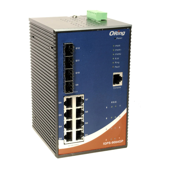
IGPS-9084GP Series User’s Manual ardware Overview 3.1 Front Panel The following table describes the labels that stick on the IGPS-9084GP series. Port Description 4 100 /1000Base-X SFP ports 8 10/100/1000Base-T(X) P.S.E. Copper Port Use RS-232 with RJ-45 connecter to manage switch. -
Page 12: Front Panel Leds
IGPS-9084GP Series User’s Manual 6. LED for Ring. When the led light on, it means the O-Ring is activated. 7. LED for Fault. When the light on, it means Power failure or Port down/fail. 8. Console port (RJ-45) 9. LED for P.O.E Status. -
Page 13: Top View Panel
IGPS-9084GP Series User’s Manual 3.3 Top view Panel The bottom panel components of IGPS-9084GP Series are showed as below: 1. Terminal block includes: PWR1, PWR2 (50-57V DC) 2. Ground wire ORing Industrial Networking Corp... -
Page 14: Cables
4.1 Ethernet Cables The IGPS-9084GP switch had standard Ethernet ports. According to the link type, the switches use CAT 3, 4, 5,5e UTP cables to connect to any other network device (PCs, servers, switches, routers, or hubs). Please refer to the following table for cable specifications. -
Page 15: 1000Base-T P.s.e. Rj-45 Port
BI_DB- BI_DD+ BI_DD- The IGPS-9084GP Series switches support auto MDI/MDI-X operation. You can use a straight-through cable to connect PC to switch. The following table below shows the 10BASE-T/ 100BASE-TX MDI and MDI-X port pin outs. 10/100 Base-T MDI/MDI-X pins assignment... -
Page 16: Sfp
Fiber cord 4.3 Console Cable IGPS-9084GP switch can be management by console port. The DB-9 to RJ-45 cable can be found in the package. You can connect them to PC via a RS-232 cable with DB-9 female ORing Industrial Networking Corp... - Page 17 IGPS-9084GP Series User’s Manual connector and the other end (RJ-45 connector) connects to console port of switch. PC pin out (male) assignment RS-232 with DB9 female connector DB9 to RJ 45 Pin #2 RD Pin #2 TD Pin #2 Pin #3 TD...
-
Page 18: Web Management
IGPS-9084GP Series User’s Manual EB Management 5.1 Configuration by Web Browser This section introduces the configuration by Web browser. 5.1.1 About Web-based Management An embedded HTML web site resides in flash memory on the CPU board. It contains advanced management features and allows you to manage the switch from anywhere on the network through a standard web browser such as Microsoft Internet Explorer. - Page 19 IGPS-9084GP Series User’s Manual The login screen appears. Key in the username and password. The default username and password is “admin”. Click “Enter” or ”OK” button, then the main interface of the Web-based management appears. Login screen Main Interface Main interface...
-
Page 20: Basic Setting
IGPS-9084GP Series User’s Manual 5.1.2 Basic Setting System Information 5.1.2.1 The switch system information is provided here. System Information interface Label Description An administratively assigned name for this managed node. By convention, this is the node's fully-qualified domain name. A... -
Page 21: Admin&Password
IGPS-9084GP Series User’s Manual Click to undo any changes made locally and revert to previously saved values. Admin&Password 5.1.2.2 This page allows you to configure the system password required to access the web pages or log in from CLI. Label... -
Page 22: Auth Method
IGPS-9084GP Series User’s Manual Auth Method 5.1.2.3 This page allows you to configure how a user is authenticated when he logs into the switch via one of the management client interfaces. Label Description Client The management client for which the configuration below applies. -
Page 23: Ip Setting
IGPS-9084GP Series User’s Manual IP Setting 5.1.2.4 Configure the switch-managed IP information on this page. Label Description Enable the DHCP client by checking this box. If DHCP fails and the configured IP address is zero, DHCP will retry. If DHCP fails... -
Page 24: Ipv6 Setting
IGPS-9084GP Series User’s Manual Click to undo any changes made locally and revert to previously saved values. IPv6 Setting 5.1.2.5 Configure the switch-managed IPv6 information on this page. Label Description Enable IPv6 auto-configuration by checking this box. If system cannot obtain the stateless address in time, the configured IPv6 Auto Configuration settings will be used. -
Page 25: Https
IGPS-9084GP Series User’s Manual example, '::192.1.2.34'. Click to save changes. Click to undo any changes made locally and revert to previously saved values. HTTPS 5.1.2.6 Label Description Indicates the HTTPS mode operation. When the current connection is HTTPS, to apply HTTPS disabled mode operation will automatically redirect web browser to an HTTP connection. -
Page 26: Ssh
IGPS-9084GP Series User’s Manual 5.1.2.7 Label Description Indicates the SSH mode operation. Possible modes are: Mode Enabled: Enable SSH mode operation. Disabled: Disable SSH mode operation. Click to save changes. Click to undo any changes made locally and revert to previously saved values. - Page 27 IGPS-9084GP Series User’s Manual Label Description Port The switch port number of the logical LLDP port. Select LLDP mode. Rx only The switch will not send out LLDP information, but LLDP information from neighbor units is analyzed. Tx only The switch will drop LLDP information received from Mode neighbors, but will send out LLDP information.
- Page 28 IGPS-9084GP Series User’s Manual 4. WLAN Access Point 5. Router 6. Telephone 7. DOCSIS cable device 8. Station only 9. Reserved When a capability is enabled, the capability is followed by (+). If the capability is disabled, the capability is followed by (-).
- Page 29 IGPS-9084GP Series User’s Manual were last changed at Total Neighbors Shows the number of new entries added since switch reboot. Entries Added Total Neighbors Shows the number of new entries deleted since switch reboot. Entries Deleted Total Neighbors Shows the number of LLDP frames dropped due to that the entry Entries Dropped table was full.
-
Page 30: Modbus Tcp
IGPS-9084GP Series User’s Manual Clears the local counters. All counters (including global counters) are cleared upon reboot. Check this box to enable an automatic refresh of the page at regular intervals. Modbus TCP 5.1.2.9 http://www.modbus.org/ Support Modbus TCP. (About Modbus please reference The following table describes the labels in this screen. -
Page 31: Firmware Update
IGPS-9084GP Series User’s Manual Firmware Update 5.1.2.11 This page facilitates an update of the firmware controlling the stack. switch. 5.1.3 DHCP Server 5.1.3.1 Setting The system provides with DHCP server function. Enable the DHCP server function, the switch system will be a DHCP server. -
Page 32: Dhcp Client List
IGPS-9084GP Series User’s Manual 5.1.3.3 DHCP Client List You can assign the specific IP address which is in the assigned dynamic IP range to the specific port. When the device is connecting to the port and asks for dynamic IP assigning, the system will assign the IP address that has been assigned before in the connected device. - Page 33 IGPS-9084GP Series User’s Manual Enabled: Enable DHCP relay mode operation. When DHCP relay mode operation is enabled, the agent forwards and transfers DHCP messages between the clients and the server when they are not in the same subnet domain. And the DHCP broadcast message won't be flooded for security considerations.
-
Page 34: Relay Statistics
IGPS-9084GP Series User’s Manual policies are: Replace: Replace the original relay information when a DHCP message that already contains it is received. Keep: Keep the original relay information when a DHCP message that already contains it is received. Drop: Drop the package when a DHCP message that already contains relay information is received. -
Page 35: Port Setting
IGPS-9084GP Series User’s Manual The following table describes the labels in this screen. Label Description Transmit to Client The number of relayed packets from server to client. Transmit Error The number of packets that resulted in error while being sent to servers. - Page 36 IGPS-9084GP Series User’s Manual Label Description Port This is the logical port number for this row. The current link state is displayed graphically. Green indicates the Link link is up and red that it is down. Current Link Speed Provides the current link speed of the port.
-
Page 37: Port Trunk
IGPS-9084GP Series User’s Manual 5.1.4.2 Port Trunk 5.1.4.2.1 Trunk Configuration This page is used to configure the Aggregation hash mode and the aggregation group. Label Description Source MAC Address The Source MAC address can be used to calculate the destination port for the frame. Check to enable the use of the Source MAC address, or uncheck to disable. -
Page 38: Lacp Port Configuration
IGPS-9084GP Series User’s Manual Label Description Group ID Indicates the group ID for the settings contained in the same row. Group ID "Normal" indicates there is no aggregation. Only one group ID is valid per port. Port Members Each switch port is listed for each group ID. Select a radio button to include a port in an aggregation, or clear the radio button to remove the port from the aggregation. - Page 39 IGPS-9084GP Series User’s Manual Label Description Port Indicates the group ID for the settings contained in the same row. Group ID "Normal" indicates there is no aggregation. Only one group ID is valid per port. LACP Enabled Each switch port is listed for each group ID. Select a radio button to include a port in an aggregation, or clear the radio button to remove the port from the aggregation.
-
Page 40: Lacp System Status
IGPS-9084GP Series User’s Manual Click to save changes. Click to undo any changes made locally and revert to previously saved values. 5.1.4.2.3 LACP System Status This page provides a status overview for all LACP instances. Label Description Aggr ID The Aggregation ID associated with this aggregation instance. For... -
Page 41: Lacp Status
IGPS-9084GP Series User’s Manual 5.1.4.2.4 LACP Status This page provides a status overview for LACP status for all ports. Label Description Port The switch port number. LACP 'Yes' means that LACP is enabled and the port link is up. 'No' means that LACP is not enabled or that the port link is down. -
Page 42: Lacp Statistics
IGPS-9084GP Series User’s Manual 5.1.4.2.5 LACP Statistics This page provides an overview for LACP statistics for all ports. Label Description Port The switch port number LACP Transmitted Shows how many LACP frames have been sent from each port LACP Received Shows how many LACP frames have been received at each port. -
Page 43: Loop Gourd
IGPS-9084GP Series User’s Manual 5.1.4.3 Loop Gourd This feature prevents the loop attack,. When the port receives loop packet. This port will auto disable, prevent the "loop attack" affect other network devices Label Description Enable Loop Protection Controls whether loop protections is enabled (as a whole). -
Page 44: Redundancy
IGPS-9084GP Series User’s Manual or Log Only. Tx Mode Controls whether the port is actively generating loop protection PDU's, or whether it is just passively looking for looped PDU's. 5.1.5 Redundancy 5.1.5.1 MRP MRP (Media Redundancy Protocol) Ring (IEC 62439) of up to 50 devices typically transforms back to a line structure within 80 ms (adjustable to max. - Page 45 IGPS-9084GP Series User’s Manual Ring interface The following table describes the labels in this screen. Label Description Mark to enable Ring. Redundant Ring There should be one and only one Ring Master in a ring. However if there are two or more switches which set Ring...
-
Page 46: O-Chain
IGPS-9084GP Series User’s Manual 5.1.5.3 O-Chain O-Chain is the revolutionary network redundancy technology that provides the add-on network redundancy topology for any backbone network, providing ease-of-use while maximizing fault-recovery swiftness, flexibility, compatibility, and cost-effectiveness in one set of network redundancy topologies O-Chain allows multiple redundant network rings of different redundancy protocols to join and function together as a larger and more robust compound network topology, i.e. -
Page 47: Mstp
IGPS-9084GP Series User’s Manual 5.1.5.4 MSTP Bridge Settings This page allows you to configure RSTP system settings. The settings are used by all RSTP Bridge instances in the Switch Stack. Label Description The STP protocol version setting. Valid values are STP, RSTP Protocol Version and MSTP. -
Page 48: Msti Mapping
IGPS-9084GP Series User’s Manual MSTI Mapping This page allows the user to inspect the current STP MSTI bridge instance priority configurations, and possibly change them as well. Label Description The name identifiying the VLAN to MSTI mapping. Bridges must share the name and revision (see below), as well as the... -
Page 49: Msti Priorities
IGPS-9084GP Series User’s Manual Click to save changes. Click to undo any changes made locally and revert to previously saved values. MSTI Priorities This page allows the user to inspect the current STP MSTI bridge instance priority configurations, and possibly change them as well. -
Page 50: Cist Ports
IGPS-9084GP Series User’s Manual CIST Ports This page allows the user to inspect the current STP CIST port configurations, and possibly change them as well. This page contains settings for physical and aggregated ports. The aggregation settings are stack global. -
Page 51: Msti Ports
IGPS-9084GP Series User’s Manual CIST or any MSTI, even if it has the best spanning tree priority vector. Such a port will be selected as an Alternate Port after the Root Port has been selected. If set, it can cause lack of spanning tree connectivity. - Page 52 IGPS-9084GP Series User’s Manual Label Description The switch port number of the corresponding STP CIST (and Port MSTI) port. Controls the path cost incurred by the port. The Auto setting will set the path cost as appropriate by the physical link speed, using the 802.1D recommended values.
-
Page 53: Stp Port Status
IGPS-9084GP Series User’s Manual STP Bridges This page provides a status overview for all STP bridge instances. The displayed table contains a row for each STP bridge instance, where the column displays the following information: Label Description The Bridge Instance. This is also a link to the STP Detailed Bridge MSTI Status. -
Page 54: Stp Statistics
IGPS-9084GP Series User’s Manual Label Description Port The switch port number of the logical STP port. The current STP port role of the CIST port. The port role can be CIST Role one of the following values: AlternatePort BackupPort RootPort DesignatedPort. -
Page 55: Fast Recovery Mode
The Fast Recovery Mode can be set to connect multiple ports to one or more switches. The IGPS-9084GP with its fast recovery mode will provide redundant links. Fast Recovery mode supports 12 priorities, only the first priority will be the act port, the other ports configured with other priority will be the backup ports. -
Page 56: Vlan
IGPS-9084GP Series User’s Manual The following table describes the labels in this screen. Label Description Active Activate the fast recovery mode. port Port can be configured as 12 priorities. Only the port with highest priority will be the active port. 1st Priority is the highest. -
Page 57: Vlan Port Configuration
IGPS-9084GP Series User’s Manual switch units, but with no port members. A VLAN without any port members on any stack unit will be deleted when you click "Save". button can be used to undo the addition of new VLANs. 5.1.6.2 VLAN Port Configuration... - Page 58 IGPS-9084GP Series User’s Manual Enable ingress filtering on a port by checking the box. This parameter affects VLAN ingress processing. If ingress filtering is Ingress Filtering enabled and the ingress port is not a member of the classified VLAN of the frame, the frame is discarded. By default, ingress filtering is disabled (no checkmark).
-
Page 59: How Is Unaware C-Port S-Port S-Customer Port
IGPS-9084GP Series User’s Manual How is Unaware C-Port S-Port S-Customer Port ? Port can be one of the following types: Unaware, C-port, S-port, and S-custom-port. Ingress action Egress action Unaware When the port received untagged frames, an The TPID of frame... - Page 60 IGPS-9084GP Series User’s Manual 1. if an tagged frame with TPID=0x88A8, it is which can be set by the forwarded. user using the column 2. if the TPID of tagged frame is not 0x88A8 (ex. of Ethertype for 0x8100), it will be discarded.
- Page 61 IGPS-9084GP Series User’s Manual ORing Industrial Networking Corp...
-
Page 62: Vlan Setting Example
IGPS-9084GP Series User’s Manual VLAN Setting Example: VLAN Access Mode Setting : Like this topology , Switch Port 7 is VLAN Access mode = Untagged 20 Port 8 is VLAN Access mode = Untagged 10 Switch setting as following ORing Industrial Networking Corp... - Page 63 IGPS-9084GP Series User’s Manual VLAN 1Q Trunk mode : Like this topology , Switch Port 1 = VLAN 1Qtrunk mode = tagged 10, 20 Port 2 = VLAN 1Qtrunk mode = tagged 10, 20 Switch setting as following ORing Industrial Networking Corp...
- Page 64 IGPS-9084GP Series User’s Manual VLAN Hybrid mode : If user want setting Port 1 VLAN Hybrid mode = untagged 10 Tagged 10, 20 Switch setting as following ORing Industrial Networking Corp...
- Page 65 IGPS-9084GP Series User’s Manual VLAN QinQ mode : On the VLAN QinQ Mode, usually used in an environment with unknown VLAN, we created a simple example as shown below. VLAN “X” = Unknown VLAN 9000 Series Port 1VLAN Setting ORing Industrial Networking Corp...
- Page 66 IGPS-9084GP Series User’s Manual VLAN Management Vlan ID Setting: If user setting Management VLAN , only same VLAN ID port , can control switch . 9000 Series VLAN Setting ORing Industrial Networking Corp...
-
Page 67: Private Vlan
IGPS-9084GP Series User’s Manual 5.1.6.3 Private VLAN The Private VLAN membership configurations for the switch can be monitored and modified here. Private VLANs can be added or deleted here. Port members of each Private VLAN can be added or removed here. Private VLANs are based on the source port mask, and there are no connections to VLANs. -
Page 68: Snmp
IGPS-9084GP Series User’s Manual button can be used to undo the addition of new Private VLANs. Label Description A check box is provided for each port of a private VLAN. When checked, port isolation is enabled for that port. Port Members When unchecked, port isolation is disabled for that port. - Page 69 IGPS-9084GP Series User’s Manual SNMP v1: Set SNMP supported version 1. SNMP v2c: Set SNMP supported version 2c. SNMP v3: Set SNMP supported version 3. Indicates the community read access string to permit access to SNMP agent. The allowed string length is 0 to 255, and the allowed content is the ASCII characters from 33 to 126.
- Page 70 IGPS-9084GP Series User’s Manual SNMP v1: Set SNMP trap supported version 1. SNMP v2c: Set SNMP trap supported version 2c. SNMP v3: Set SNMP trap supported version 3. Indicates the community access string when send SNMP trap packet. Trap Community The allowed string length is 0 to 255, and the allowed content is the ASCII characters from 33 to 126.
-
Page 71: Snmp-Communities
IGPS-9084GP Series User’s Manual Indicates the SNMP trap security engine ID. SNMPv3 sends traps and informs using USM for authentication and privacy. A unique engine ID for these traps and informs is needed. When "Trap Probe Trap Security Security Engine ID" is enabled, the ID will be probed automatically. -
Page 72: Snmp-Users
IGPS-9084GP Series User’s Manual 5.1.7.3 SNMP-Users Configure SNMPv3 users table on this page. The entry index keys are Engine ID and User Name. Label Description Delete Check to delete the entry. It will be deleted during the next save. An octet string identifying the engine ID that this entry should belong to. -
Page 73: Snmp-Groups
IGPS-9084GP Series User’s Manual MD5: An optional flag to indicate that this user using MD5 authentication protocol. SHA: An optional flag to indicate that this user using SHA authentication protocol. The value of security level cannot be modified if entry already exists. -
Page 74: Snmp-Views
IGPS-9084GP Series User’s Manual v1: Reserved for SNMPv1. v2c: Reserved for SNMPv2c. usm: User-based Security Model (USM). A string identifying the security name that this entry should belong to. Security Name The allowed string length is 1 to 32, and the allowed content is the ASCII characters from 33 to 126. -
Page 75: Snmp-Accesses
IGPS-9084GP Series User’s Manual The allowed OID length is 1 to 128. The allowed string content is digital number or asterisk(*). 5.1.7.6 SNMP-Accesses Configure SNMPv3 accesses table on this page. The entry index keys are Group Name, Security Model and Security Level. -
Page 76: Traffic Prioritization
IGPS-9084GP Series User’s Manual 5.1.8 Traffic Prioritization 5.1.8.1 Stom Control There is a unicast storm rate control, multicast storm rate control, and a broadcast storm rate control. These only affect flooded frames, i.e. frames with a (VLAN ID, DMAC) pair not present on the MAC Address table. -
Page 77: Port Classifcation
IGPS-9084GP Series User’s Manual 5.1.8.2 Port Classifcation QoS is an acronym for Quality of Service. It is a method to guarantee a bandwidth relationship between individual applications or protocols. Label Description Port The port number for which the configuration below applies Controls the default QoS class. - Page 78 IGPS-9084GP Series User’s Manual mapped from the PCP and DEI value in the tag. Otherwise the frame is classified to the default QoS class. The classified QoS class can be overruled by a QCL entry. Note: If the default QoS class has been dynamically changed, then the actual default QoS class is shown in parentheses after the configured default QoS class.
-
Page 79: Port Tag Remaking
IGPS-9084GP Series User’s Manual Shows the classification mode for tagged frames on this port. Disabled: Use default QoS class and DP level for tagged frames. Enabled: Use mapped versions of PCP and DEI for tagged frames. Click on the mode in order to configure the mode and/or mapping. -
Page 80: Port Dscp
IGPS-9084GP Series User’s Manual 5.1.8.4 Port DSCP This page allows you to configure the basic QoS Port DSCP Configuration settings for all switch ports. Label Description The Port column shows the list of ports for which you can Port configure dscp ingress and egress settings. -
Page 81: Port Policing
IGPS-9084GP Series User’s Manual •All: Classify all DSCP. Port Egress Rewriting can be one of - •Disable: No Egress rewrite. •Enable: Rewrite enabled without remapping. •Remap DP Unaware: DSCP from analyzer is remapped and frame is remarked with remapped DSCP value. The remapped Egress DSCP value is always taken from the 'DSCP Translation->Egress... -
Page 82: Queue Policing
IGPS-9084GP Series User’s Manual Label Description Port The port number for which the configuration below applies Enable Controls whether the policer is enabled on this switch port. Controls the rate for the policer. The default value is 500. This value is restricted to 100-1000000 when the "Unit" is "kbps" or Rate "fps", and it is restricted to 1-3300 when the "Unit"... -
Page 83: Qos Egress Port Scheduler And Shapers
IGPS-9084GP Series User’s Manual 5.1.8.7 QoS Egress Port Scheduler and Shapers This page allows you to configure the Scheduler and Shapers for a specific port. Strict Priority Label Description Controls whether the scheduler mode is "Strict Priority" or Scheduler Mode "Weighted"... - Page 84 IGPS-9084GP Series User’s Manual This value is restricted to 100-1000000 when the "Unit" is "kbps", and it is restricted to 1-3300 when the "Unit" is "Mbps". Queue Shaper Controls whether the queue is allowed to use excess bandwidth. Excess Port Shaper Enable Controls whether the port shaper is enabled for this switch port.
-
Page 85: Port Schedulet
IGPS-9084GP Series User’s Manual Label Description Controls whether the scheduler mode is "Strict Priority" or Scheduler Mode "Weighted" on this switch port. Queue Shaper Controls whether the queue shaper is enabled for this queue on Enable this switch port. Controls the rate for the queue shaper. The default value is 500. -
Page 86: Port Shaping
IGPS-9084GP Series User’s Manual Label Description The logical port for the settings contained in the same row. Port Click on the port number in order to configure the schedulers. Mode Shows the scheduling mode for this port. Shows the weight for this queue and port. -
Page 87: Dscp Translation
IGPS-9084GP Series User’s Manual Label Description DSCP Maximum number of supported DSCP values are 64.. Controls whether a specific DSCP value is trusted. Only frames with trusted DSCP values are mapped to a specific QoS class and Trust Drop Precedence Level. Frames with untrusted DSCP values are treated as a non-IP frame. -
Page 88: Dscp Classification
IGPS-9084GP Series User’s Manual values. 2.Classify Click to enable Classification at Ingress side. There are the following configurable parameters for Egress side – Egress 1. Remap DP0 Controls the remapping for frames with DP level 0. 2. Remap DP1 Controls the remapping for frames with DP level 1. -
Page 89: Qos Control List
IGPS-9084GP Series User’s Manual 5.1.8.13 QoS Control List This page allows to edit|insert a single QoS Control Entry at a time. A QCE consists of several parameters. These parameters vary according to the frame type that you select. Label Description Check the checkbox button to include the port in the QCL entry. - Page 90 IGPS-9084GP Series User’s Manual 1. Any 2. Ethernet 3. LLC 4. SNAP 5. IPv4 6. IPv6 Note: All frame types are explained below. 1.Any Allow all types of frames. Ethernet Type Valid ethernet type can have a value within 2. Ethernet...
-
Page 91: Qos Counters
IGPS-9084GP Series User’s Manual value, range of values or 'Any'. DSCP values are in the range 0-63 including BE, CS1-CS7, EF or AF11-AF43. Sport Source TCP/UDP port:(0-65535) or 'Any', specific or port range applicable for IP protocol UDP/TCP. Dport Destination TCP/UDP port:(0-65535) or 'Any', specific or port range applicable for IP protocol UDP/TCP. -
Page 92: Qcl Status
IGPS-9084GP Series User’s Manual 5.1.8.15 QCL Status This page shows the QCL status by different QCL users. Each row describes the QCE that is defined. It is a conflict if a specific QCE is not applied to the hardware due to hardware limitations. -
Page 93: Multicast
IGPS-9084GP Series User’s Manual required to add a QCE may not be available, in that case it shows conflict status as 'Yes', otherwise it is always 'No'. Please note that conflict can be resolved by releasing the H/W resources required to add QCL entry on pressing 'Resolve Conflict' button. -
Page 94: Igmp Snooping- Vlan Configuration
IGPS-9084GP Series User’s Manual 5.1.9.2 IGMP Snooping- VLAN Configuration- Each page shows up to 99 entries from the VLAN table, default being 20, selected through the "entries per page" input field. When first visited, the web page will show the first 20 entries from the beginning of the VLAN Table. -
Page 95: Igmp Snooping Status
IGPS-9084GP Series User’s Manual 5.1.9.3 IGMP Snooping Status This page provides IGMP Snooping status. Label Description VLAN ID The VLAN ID of the entry. Querier Version Working Querier Version currently. Host Version Working Host Version currently. Querier Status Show the Querier status is "ACTIVE" or "IDLE". -
Page 96: Igmp Snooping Groups Information
IGPS-9084GP Series User’s Manual 5.1.9.4 IGMP Snooping Groups Information Entries in the IGMP Group Table are shown on this page. The IGMP Group Table is sorted first by VLAN ID, and then by group. Label Description VLAN ID VLAN ID of the group. -
Page 97: Device Binding
IGPS-9084GP Series User’s Manual IP address of remote client. Keeps this field "0.0.0.0" means "Any IP Address IP". Check this item to enable Web management interface. Telnet Check this item to enable Telnet management interface. SNMP Check this item to enable SNMP management interface Delete Check this item to delete. -
Page 98: Advanced Configuration
IGPS-9084GP Series User’s Manual Active stream change(getting low) from device. Indicates the Stream Check status. Possible statuses are: Stream Check ---: Disable. Status Normal: The stream is normal. Low: The stream is getting low. DDoS Prevention Enable/Disable DDOS Prevention. When enabled, switch will monitor Acton the device to against DDOS attack (from device). - Page 99 IGPS-9084GP Series User’s Manual Alive Check using the ping command ,check port link status, if port link fail .user can setting action field , select the switch action. Label Description Link Change Disable and enable port . Only log it Only sent log to log server .
- Page 100 IGPS-9084GP Series User’s Manual Label Description Mode Enable/Disable DDOS Prevention of the port. Indicates the level of DDOS detection. Possible levels are: Low: Low sensibility. Sensibility Normal: Normal sensibility. Medium: Medium sensibility. High: High sensibility. Indicates the packet type of DDOS monitor. Possible types are: RX Total: Total ingress packets.
-
Page 101: Device Description
IGPS-9084GP Series User’s Manual Device Description This page provides Device Description related configuration Label Description Indicates the type of device. Possible types are: ---: No specification. IP Camera: IP Camera. IP Phone: IP Phone. Device Type Access Point: Access Point. -
Page 102: Acl
IGPS-9084GP Series User’s Manual Stream Check This page provides Stream Check related configuration. Label Description Mode Enable/Disable stream monitor of the port. Indicates the action when stream getting low. Possible actions are: Action ---: Do nothing. Log it: Just log the event 5.1.10.3 ACL... -
Page 103: Rate Limiters
IGPS-9084GP Series User’s Manual Label Description Port The logical port for the settings contained in the same row. Select the policy to apply to this port. The allowed values are 1 Policy ID through 8. The default value is 1. - Page 104 IGPS-9084GP Series User’s Manual Label Description Rate Limiter ID The rate limiter ID for the settings contained in the same row. The rate unit is packet per second (pps), configure the rate as 1, 2, 4, 8, 16, 32, 64, 128, 256, 512, 1K, 2K, 4K, 8K, 16K, 32K, 64K, 128K, Rate 256K, 512K, or 1024K.
- Page 105 IGPS-9084GP Series User’s Manual should be greater than or equal to 1536 decimal (equal to 0600 hexadecimal). ARP: Only ARP frames can match this ACE. Notice the ARP frames won't match the ACE with etnernet type. IPv4: Only IPv4 frames can match this ACE. Notice the IPv4 frames won't match the ACE with etnernet type.
- Page 106 IGPS-9084GP Series User’s Manual Label Description (Only displayed when the frame type is Ethernet Type or ARP.) Specify the source MAC filter for this ACE. SMAC Filter Any: No SMAC filter is specified. (SMAC filter status is "don't-care".) Specific: If you want to filter a specific source MAC address with this ACE, choose this value.
- Page 107 IGPS-9084GP Series User’s Manual When "Specific" is selected for the VLAN ID filter, you can enter a VLAN ID specific VLAN ID number. The allowed range is 1 to 4095. A frame that hits this ACE matches this VLAN ID value.
- Page 108 IGPS-9084GP Series User’s Manual Specify the Time-to-Live settings for this ACE. zero: IPv4 frames with a Time-to-Live field greater than zero must not be able to match this entry. IP TTL non-zero: IPv4 frames with a Time-to-Live field greater than zero must be able to match this entry.
- Page 109 IGPS-9084GP Series User’s Manual destination IP address and destination IP mask in the DIP Address and DIP Mask fields that appear. When "Host" or "Network" is selected for the destination IP filter, you DIP Address can enter a specific DIP address in dotted decimal notation.
- Page 110 IGPS-9084GP Series User’s Manual enter a specific sender IP address in dotted decimal notation. When "Network" is selected for the sender IP filter, you can enter a Sender IP Mask specific sender IP mask in dotted decimal notation. Specify the target IP filter for this specific ACE.
- Page 111 IGPS-9084GP Series User’s Manual Any: Any value is allowed ("don't-care"). Specify whether frames can hit the action according to their ARP/RARP protocol address space (PRO) settings. 0: ARP/RARP frames where the PRO is equal to IP (0x800) must not Ethernet match this entry.
- Page 112 IGPS-9084GP Series User’s Manual Label Description Specify the TCP/UDP source filter for this ACE. Any: No TCP/UDP source filter is specified (TCP/UDP source filter status is "don't-care"). Specific: If you want to filter a specific TCP/UDP source filter with this TCP/UDP Source ACE, you can enter a specific TCP/UDP source value.
- Page 113 IGPS-9084GP Series User’s Manual range value. A field for entering a TCP/UDP destination value appears. When "Specific" is selected for the TCP/UDP destination filter, you TCP/UDP can enter a specific TCP/UDP destination value. The allowed range Destination is 0 to 65535. A frame that hits this ACE matches this TCP/UDP Number destination value.
-
Page 114: Aaa
IGPS-9084GP Series User’s Manual Specify the TCP "Urgent Pointer field significant" (URG) value for this ACE. 0: TCP frames where the URG field is set must not be able to match TCP URG this entry. 1: TCP frames where the URG field is set must be able to match this entry. -
Page 115: Radius Accounting Server Configuration
IGPS-9084GP Series User’s Manual feature, but only if more than one server has been configured. 5.1.10.4.2 RADIUS Authentication Server Configuration The table has one row for each RADIUS Authentication Server and a number of columns, which are: Label Description The RADIUS Authentication Server number for which the configuration below applies. -
Page 116: Radius Overview
IGPS-9084GP Series User’s Manual Label Description The RADIUS Accounting Server number for which the configuration below applies. Enabled Enable the RADIUS Accounting Server by checking this box. The IP address or hostname of the RADIUS Accounting Server. IP IP Address address is expressed in dotted decimal notation. -
Page 117: Radius Accounting Servers
IGPS-9084GP Series User’s Manual and the RADIUS module is ready to accept access attempts. Dead (X seconds left): Access attempts were made to this server, but it did not reply within the configured timeout. The server has temporarily been disabled, but will get re-enabled when the dead-time expires. -
Page 118: Radius Details
IGPS-9084GP Series User’s Manual 5.1.10.6 RADIUS Details The statistics map closely to those specified in RFC4668 - RADIUS Authentication Client MIB. Use the server select box to switch between the backend servers to show details for. The statistics map closely to those specified in RFC4668 - RADIUS Authentication Client MIB. - Page 119 IGPS-9084GP Series User’s Manual This section contains information about the state of the server and the latest round-trip time. Other Info Label Description RADIUS accounting server packet counter. There are five receive and four transmit counters. Packet Counters ORing Industrial Networking Corp...
-
Page 120: Nas(802.1X)
IGPS-9084GP Series User’s Manual This section contains information about the state of the server and the latest Other Info 5.1.10.7 NAS(802.1x) This page allows you to configure the IEEE 802.1X and MAC-based authentication system and port settings. The IEEE 802.1X standard defines a port-based access control procedure that prevents unauthorized access to a network by requiring users to first submit credentials for authentication. - Page 121 IGPS-9084GP Series User’s Manual that the authenticator (the switch) doesn't need to know which authentication method the supplicant and the authentication server are using, or how many information exchange frames are needed for a particular method. The switch simply encapsulates the EAP part of the frame into the relevant type (EAPOL or RADIUS) and forwards it.
- Page 122 IGPS-9084GP Series User’s Manual method is supported. The 802.1X and MAC-Based Authentication configuration consists of two sections, a system- and a port-wide Label Description Indicates if 802.1X and MAC-based authentication is globally Mode enabled or disabled on the switch. If globally disabled, all ports are allowed forwarding of frames.
- Page 123 IGPS-9084GP Series User’s Manual in the range 1 to 3600 seconds. Determines the time for retransmission of Request Identity EAPOL frames. EAPOL Timeout Valid values are in the range 1 to 65535 seconds. This has no effect for MAC-based ports.
- Page 124 IGPS-9084GP Series User’s Manual when the port link comes up, and any client on the port will be allowed network access without authentication. Force Unauthorized In this mode, the switch will send one EAPOL Failure frame when the port link comes up, and any client on the port will be disallowed network access.
- Page 125 IGPS-9084GP Series User’s Manual on-going backend authentication server requests whenever it receives a new EAPOL Start frame from the supplicant. And since the server hasn't yet failed (because the X seconds haven't expired), the same server will be contacted upon the next backend authentication server request from the switch.
- Page 126 IGPS-9084GP Series User’s Manual Multi 802.1X is really not an IEEE standard, but features many of the same characteristics as does port-based 802.1X. Multi 802.1X is - like Single 802.1X - not an IEEE standard, but a variant that features many of the same characteristics. In Multi 802.1X, one or more supplicants can get authenticated on the same port at the same time.
- Page 127 IGPS-9084GP Series User’s Manual Security module. Only then will frames from the client be forwarded on the switch. There are no EAPOL frames involved in this authentication, and therefore, MAC-based Authentication has nothing to do with the 802.1X standard. The advantage of MAC-based authentication over port-based 802.1X is that several clients can be connected to the same port...
- Page 128 IGPS-9084GP Series User’s Manual immediately. The button only has effect for successfully authenticated clients on the port and will not cause the clients to get temporarily unauthorized. Reinitialize: Forces a reinitialization of the clients on the port and thereby a reauthentication immediately. The clients will transfer to the unauthorized state while the reauthentication is in progress.
- Page 129 IGPS-9084GP Series User’s Manual This page provides detailed IEEE 802.1X statistics for a specific switch port running port-based authentication. For MAC-based ports, it shows selected backend server (RADIUS Authentication Server) statistics, only. Use the port select box to select which port details to be displayed.
- Page 130 IGPS-9084GP Series User’s Manual • 802.1X • MAC-based Auth. Information about the last supplicant/client that attempted to authenticate. This information available for following administrative states: • 802.1X • MAC-based Auth. Last Supplicant/Client Info ORing Industrial Networking Corp...
-
Page 131: Warning
IGPS-9084GP Series User’s Manual 5.1.11 Warning 5.1.11.1 Fault Alarm When any selected fault event is happened, the Fault LED in switch panel will light up and the electric relay will signal at the same time. 5.1.11.2 System Warning 5.1.11.2.1 SYSLOG Setting The SYSLOG is a protocol to transmit event notification messages across networks. -
Page 132: Smtp Setting
IGPS-9084GP Series User’s Manual syslog server will not send acknowledgments back sender since UDP is a connectionless protocol and it does not provide acknowledgments. The syslog packet will always send out even if the syslog server does not exist. Possible modes are: Enabled: Enable server mode operation. -
Page 133: Event Selection
IGPS-9084GP Series User’s Manual Confirm Password: re-enter password. Recipient E-mail The recipient's E-mail address. It supports 6 recipients for a Address mail. Apply Click “Apply” to activate the configurations. Help Show help file. 5.1.11.2.3 Event Selection SYSLOG and SMTP are the two warning methods that supported by the system. Check the corresponding box to enable system event warning method you wish to choose. -
Page 134: Monitor And Diag
IGPS-9084GP Series User’s Manual Change Port Event Disable SYSLOG / SMTP Link Up event Link Down Link Up & Link Down Apply Click “Apply” to activate the configurations. Help Show help file. 5.1.12 Monitor and Diag 5.1.12.1 MAC Table 5.1.12.1.1 Configuration The MAC Address Table is configured on this page. -
Page 135: Mac Table Learning
IGPS-9084GP Series User’s Manual Configure aging time by entering a value here in seconds; for example, Age time seconds. The allowed range is 10 to 1000000 seconds. Disable the automatic aging of dynamic entries by checking Disable automatic aging. MAC Table Learning If the learning mode for a given port is grayed out, another module is in control of the mode, so that it cannot be changed by the user. - Page 136 IGPS-9084GP Series User’s Manual Label Description Delete Check to delete the entry. It will be deleted during the next save. VLAN ID The VLAN ID for the entry. MAC Address The MAC address for the entry. Checkmarks indicate which ports are members of the entry.
-
Page 137: Port Statistic
IGPS-9084GP Series User’s Manual Label Description Type Indicates whether the entry is a static or dynamic entry. MAC address The MAC address of the entry. VLAN The VLAN ID of the entry. Port Members The ports that are members of the entry. -
Page 138: Detailed Statistics
IGPS-9084GP Series User’s Manual The number of frames received in error and the number of Errors incomplete transmissions per port. The number of frames discarded due to ingress or egress Drops congestion. Filtered The number of received frames filtered by the forwarding process. -
Page 139: Port Mirroring
IGPS-9084GP Series User’s Manual Label Description Rx and Tx Packets The number of received and transmitted (good and bad) packets. The number of received and transmitted (good and bad) bytes. Rx and Tx Octets Includes FCS, but excludes framing bits. - Page 140 IGPS-9084GP Series User’s Manual Port to mirror also knwon as the mirror port. Frames from ports that have either source (rx) or destination (tx) mirroring enabled are mirrored to this port. Disabled disables mirroring. Label Description Port The logical port for the settings contained in the same row.
-
Page 141: System Log Information
IGPS-9084GP Series User’s Manual 5.1.12.4 System Log Information The switch system log information is provided here. Label Description The ID (>= 1) of the system log entry. The level of the system log entry. The following level types are supported: Info: Information level of the system log. -
Page 142: Cable Diagnostics
IGPS-9084GP Series User’s Manual 5.1.12.5 Cable Diagnostics This page is used for running the VeriPHY Cable Diagnostics. Press to run the diagnostics. This will take approximately 5 seconds. If all ports are selected, this can take approximately 15 seconds. When completed, the page refreshes automatically, and you can view the cable diagnostics results in the cable status table. -
Page 143: Ping
IGPS-9084GP Series User’s Manual 5.1.12.7 Ping This page allows you to issue ICMP PING packets to troubleshoot IP connectivity issues. After you press , 5 ICMP packets are transmitted, and the sequence number and roundtrip time are displayed upon reception of a reply. The page refreshes automatically until responses to all packets are received, or until a timeout occurs. -
Page 144: Ipv6 Ping
IGPS-9084GP Series User’s Manual 64 bytes from ::10.10.132.20: icmp_seq=1, time=0ms 64 bytes from ::10.10.132.20: icmp_seq=2, time=0ms 64 bytes from ::10.10.132.20: icmp_seq=3, time=0ms 64 bytes from ::10.10.132.20: icmp_seq=4, time=0ms Sent 5 packets, received 5 OK, 0 bad You can configure the following properties of the issued ICMP packets:... -
Page 145: Synchronization-Ptp
IGPS-9084GP Series User’s Manual 5.1.13 Synchronization-PTP Overview of MAC-Based Authentication This page allows the user to configure and inspect the current PTP clock settings. PTP External Clock Mode Label Description One_pps_mode This Selection box will allow you to select the One_pps_mode configuration. - Page 146 IGPS-9084GP Series User’s Manual PTP Clock Configuration Label Description Delete Check this box and click on 'Save' to delete the clock instance. Clock Instance Indicates the Instance of a particular Clock Instance [0..3]. Click on the Clock Instance number to edit the Clock details.
-
Page 147: Poe
IGPS-9084GP Series User’s Manual only clocks See parameter Device Type In a unicast Slave only clock you also need configure which master clocks to request Announce and Sync messages from. See: Unicast Slave Configuration VLAN Tag Enable Enables the VLAN tagging for the PTP frames. - Page 148 IGPS-9084GP Series User’s Manual Label Description Reserved Power There are three modes for configuring how the ports/PDs may determined by reserve power. 1. Allocated mode: In this mode the user allocates the amount of power that each port may reserve. The allocated/reserved power for each port/PD is specified in the Maximum Power fields.
-
Page 149: Status
IGPS-9084GP Series User’s Manual over. For being able to determine the amount of power the PD may use, it must be defined what amount of power the primary and backup power sources can deliver. Valid values are in the range 0 to 2000 Watts. - Page 150 IGPS-9084GP Series User’s Manual Label Description Local Port This is the logical port number for this row. PD Class Each PD is classified according to a class that defines the maximum power the PD will use. The PD Class shows the PDs class.
-
Page 151: Factory Defaults
IGPS-9084GP Series User’s Manual PoE turned OFF - PD is off. Invalid PD - PD detected, but is not working correctly. 5.1.15 Factory Defaults You can reset the configuration of the stack switch on this page. Only the IP configuration is retained. - Page 152 IGPS-9084GP Series User’s Manual Label Description Click to reboot device. Click to return to the Port State page without rebooting. ORing Industrial Networking Corp...
-
Page 153: Command Line Interface Management
IGPS-9084GP Series User’s Manual ommand Line Interface Management About CLI Management Besides WEB-base management, IGPS-9084GP also support CLI management. You can use console or telnet to management switch by CLI. CLI Management by RS-232 Serial Console (115200, 8, none, 1, none) Before Configuring by RS-232 serial console, use an RJ45 to DB9-F cable to connect the Switches’... - Page 154 IGPS-9084GP Series User’s Manual Step 2. Input a name for new connection Step 3. Select to use COM port number ORing Industrial Networking Corp...
- Page 155 IGPS-9084GP Series User’s Manual Step 4. The COM port properties setting, 115200 for Bits per second, 8 for Data bits, None for Parity, 1 for Stop bits and none for Flow control. Step 5. The Console login screen will appear. Use the keyboard to enter the Username and Password (The same with the password for Web Browser), then press “Enter”.
- Page 156 IGPS-9084GP Series User’s Manual CLI Management by Telnet Users can use “TELNET” to configure the switches. The default value is as below: IP Address: 192.168.10.1 Subnet Mask: 255.255.255.0 Default Gateway: 192.168.10.254 User Name: admin Password: admin Follow the steps below to access the console via Telnet.
- Page 157 IGPS-9084GP Series User’s Manual Commander Groups System Configuration [all] [<port_list>] Reboot Restore Default [keep_ip] Contact [<contact>] Name [<name>] Location [<location>] System> Description [<description>] Password <password> Username [<username>] Timezone [<offset>] Log [<log_id>] [all|info|warning|error] [clear] ORing Industrial Networking Corp...
- Page 158 IGPS-9084GP Series User’s Manual Configuration DHCP [enable|disable] IP> Setup [<ip_addr>] [<ip_mask>] [<ip_router>] [<vid>] Ping <ip_addr_string> [<ping_length>] SNTP [<ip_addr_string>] Port Configuration [<port_list>] [up|down] Mode [<port_list>] [auto|10hdx|10fdx|100hdx|100fdx|1000fdx|sfp_auto_ams] Flow Control [<port_list>] [enable|disable] State [<port_list>] [enable|disable] MaxFrame [<port_list>] [<max_frame>] port> Power [<port_list>] [enable|disable|actiphy|dynamic] Excessive [<port_list>] [discard|restart] Statistics [<port_list>] [<command>] [up|down]...
- Page 159 IGPS-9084GP Series User’s Manual VLAN Configuration [<port_list>] PVID [<port_list>] [<vid>|none] FrameType [<port_list>] [all|tagged|untagged] IngressFilter [<port_list>] [enable|disable] tx_tag [<port_list>] [untag_pvid|untag_all|tag_all] PortType [<port_list>] [unaware|c-port|s-port|s-custom-port] EtypeCustomSport [<etype>] Add <vid>|<name> [<ports_list>] VLAN> Forbidden Add <vid>|<name> [<port_list>] Delete <vid>|<name> Forbidden Delete <vid>|<name> Forbidden Lookup [<vid>] [(name <name>)] Lookup [<vid>] [(name <name>)] [combined|static|nas|all]...
- Page 160 IGPS-9084GP Series User’s Manual Security Switch Password <password> Auth Authentication Secure Shell Security/switch> HTTPS Hypertext Transfer Protocol over Secure Socket Layer RMON Remote Network Monitoring Security Switch Authentication Configuration Security/switch/auth> Method [console|telnet|ssh|web] [none|local|radius] [enable|disable] Security Switch SSH Configuration Security/switch/ssh> Mode [enable|disable]...
- Page 161 IGPS-9084GP Series User’s Manual Security Network Psec Port Security Status Network Access Server (IEEE 802.1X) Security/Network> Access Control List DHCP Dynamic Host Configuration Protocol Security Network Psec Switch [<port_list>] Security/Network/Psec> Port [<port_list>] Security Network NAS Configuration [<port_list>] Mode [enable|disable] State [<port_list>] [auto|authorized|unauthorized|macbased] Reauthentication [enable|disable] ReauthPeriod [<reauth_period>]...
- Page 162 IGPS-9084GP Series User’s Manual (udp [<sip>] [<dip>] [<sport>] [<dport>] [<ip_flags>]) | (tcp [<sip>] [<dip>] [<sport>] [<dport>] [<ip_flags>] [<tcp_flags>])] [permit|deny] [<rate_limiter>] [<port_redirect>] [<mirror>] [<logging>][<shutdown>] Delete <ace_id> Lookup [<ace_id>] Clear Status [combined|static|loop_protect|dhcp|ptp|ipmc|conflicts] Port State [<port_list>] [enable|disable] Security Network DHCP Configuration Mode [enable|disable] Server [<ip_addr>]...
- Page 163 IGPS-9084GP Series User’s Manual FwdDelay [<delay>] bpduFilter [enable|disable] bpduGuard [enable|disable] recovery [<timeout>] CName [<config-name>] [<integer>] Status [<msti>] [<port_list>] Msti Priority [<msti>] [<priority>] Msti Map [<msti>] [clear] Msti Add <msti> <vid> Port Configuration [<port_list>] Port Mode [<port_list>] [enable|disable] Port Edge [<port_list>] [enable|disable] Port AutoEdge [<port_list>] [enable|disable]...
- Page 164 IGPS-9084GP Series User’s Manual Status [<port_list>] Statistics [<port_list>] [clear] LLDP Configuration [<port_list>] Mode [<port_list>] [enable|disable] LLDP> Statistics [<port_list>] [clear] Info [<port_list>] Configuration [<port_list>] Mode [<port_list>] [disabled|poe|poe+] Priority [<port_list>] [low|high|critical] PoE> Mgmt_mode [class_con|class_res|al_con|al_res|lldp_res|lldp_con] Maximum_Power [<port_list>] [<port_power>] Status Primary_Supply [<supply_power>] DSCP Map [<dscp_list>] [<class>] [<dpl>] DSCP Translation [<dscp_list>] [<trans_dscp>]...
- Page 165 IGPS-9084GP Series User’s Manual [<dport>]) | (ipv6 [<protocol>] [<sip_v6>] [<dscp>] [<sport>] [<dport>])] [<class>] [<dp>] [<classified_dscp>] QCL Delete <qce_id> QCL Lookup [<qce_id>] QCL Status [combined|static|conflicts] QCL Refresh Mirror Configuration [<port_list>] Mirror> Port [<port>|disable] Mode [<port_list>] [enable|disable|rx|tx] Dot1x Configuration [<port_list>] Mode [enable|disable] State [<port_list>] [macbased|auto|authorized|unauthorized]...
- Page 166 IGPS-9084GP Series User’s Manual Configuration [<port_list>] Action [<port_list>] [permit|deny] [<rate_limiter>] [<port_copy>] [<logging>] [<shutdown>] Policy [<port_list>] [<policy>] Rate [<rate_limiter_list>] [<packet_rate>] Add [<ace_id>] [<ace_id_next>] [switch | (port <port>) | (policy <policy>)] [<vid>] [<tag_prio>] [<dmac_type>] [(etype [<etype>] [<smac>] [<dmac>]) | ACL> (arp [<sip>] [<dip>] [<smac>] [<arp_opcode>] [<arp_flags>]) | [<sip>] [<dip>] [<protocol>] [<ip_flags>]) |...
- Page 167 IGPS-9084GP Series User’s Manual SNMP Trap Inform Retry Times [<retries>] Trap Probe Security Engine ID [enable|disable] Trap Security Engine ID [<engineid>] Trap Security Name [<security_name>] Engine ID [<engineid>] Community Add <community> [<ip_addr>] [<ip_mask>] Community Delete <index> Community Lookup [<index>] User Add <engineid> <user_name> [MD5|SHA] [<auth_password>] [DES] [<priv_password>]...
- Page 168 IGPS-9084GP Series User’s Manual DefaultDS <clockinst> [<priority1>] [<priority2>] [<domain>] CurrentDS <clockinst> ParentDS <clockinst> Timingproperties <clockinst> [<utcoffset>] [<valid>] [<leap59>] [<leap61>] [<timetrac>] [<freqtrac>] [<ptptimescale>] [<timesource>] PTP PortDataSet <clockinst> [<port_list>] [<announceintv>] [<announceto>] [<syncintv>] [<delaymech>] [<minpdelayreqintv>] [<delayasymmetry>] [<ingressLatency>] LocalClock <clockinst> [update|show|ratio] [<clockratio>] Filter <clockinst> [<def_delay_filt>] [<period>] [<dist>] Servo <clockinst>...
- Page 169 IGPS-9084GP Series User’s Manual IPMC Configuration [igmp] Mode [igmp] [enable|disable] Flooding [igmp] [enable|disable] VLAN Add [igmp] <vid> VLAN Delete [igmp] <vid> State [igmp] [<vid>] [enable|disable] IPMC> Querier [igmp] [<vid>] [enable|disable] Fastleave [igmp] [<port_list>] [enable|disable] Router [igmp] [<port_list>] [enable|disable] Status [igmp] [<vid>] Groups [igmp] [<vid>]...
- Page 170 IGPS-9084GP Series User’s Manual Ring Mode [enable|disable] Master [enable|disable] 1stRingPort [<port>] 2ndRingPort [<port>] Ring> Couple Mode [enable|disable] Couple Port [<port>] Dualhoming Mode [enable|disable] Dualhoming Port [<port>] Chain Configuration Mode [enable|disable] 1stUplinkPort [<port>] Chain> 2ndUplinkPort [<port>] EdgePort [1st|2nd|none] Mode [enable|disable] Add [<ip_addr>] [<port_list>] [web_on|web_off] [telnet_on|telnet_off] [snmp_on|snmp_off] RCS>...
- Page 171 IGPS-9084GP Series User’s Manual Port Mode [<port_list>] [disable|scan|binding|shutdown] Port DDOS Mode [<port_list>] [enable|disable] Port DDOS Sensibility [<port_list>] [low|normal|medium|high] Port DDOS Packet [<port_list>] [rx_total|rx_unicast|rx_multicast|rx_broadcast|tcp|udp] Port DDOS Low [<port_list>] [<socket_number>] Port DDOS High [<port_list>] [<socket_number>] Port DDOS Filter [<port_list>] [source|destination] Port DDOS Action [<port_list>]...
- Page 172 IGPS-9084GP Series User’s Manual Parameter MRP_TSTdefaultT [<value>] Parameter MRP_TSTNRmax [<value>] Parameter MRP_LNKdownT [<value>] Parameter MRP_LNKupT [<value>] Parameter MRP_LNKNRmax [<value>] Modbus Status Modbus> Mode [enable|disable] ORing Industrial Networking Corp...
-
Page 173: T Echnical Specifications
Specifications ORing Switch Model IGPS-9084GP Physical Ports 10/100/1000Base-T(X) with P.S.E. Ports in RJ45 Auto MDI/MDIX 100/1000Base-X with SFP port Technology IEEE 802.3 for 10Base-T IEEE 802.3u for 100Base-TX and 100Base-FX IEEE 802.3ab for 1000Base-T IEEE 802.z for 1000Base-X IEEE 802.3x for Flow control IEEE 802.3ad for LACP (Link Aggregation Control Protocol ) - Page 174 IGPS-9084GP Series User’s Manual Green : Indicates that the system operating in O-Ring mode O-Ring Indicator (Ring) Green Blinking : Indicates that the Ring is broken. Fault Indicator (Fault) Amber : Indicate unexpected event occurred 10/100/1000Base-T(X) RJ45 Port Dual color LED : Green for 1000Mbps Link/Act indicator. Amber for 10/100Mbps Link/Act indicator...
Need help?
Do you have a question about the IGPS-9084GP and is the answer not in the manual?
Questions and answers