ORiNG RGS-R9004GP+ME-HV Quick Installation Manual
Industrial layer 3 modular rack mount managed gigabit switch
Hide thumbs
Also See for RGS-R9004GP+ME-HV:
- User manual (211 pages) ,
- Quick installation manual (2 pages)
Advertisement
Quick Links
GIGABIT
SWITCH
LAYER 3
Q
I
uick
nstallation
M A N A G E D
Rack-Mount
Introduction
RGS-R9004GP+ME-HV is Layer-3 modular managed redundant ring
Ethernet switch with 6 slots, up to 48 ports, and has 4 fixed 10G SFP+ ports.
With such high port density and modular design, it makes network planning
easier. With completely support of Ethernet Redundancy protocol, O-Ring
(recovery time < 30ms) and MSTP (RSTP/STP compatible) can protect your
mission-critical applications from network interruptions or temporary
malfunctions with its fast recovery technology. And support wide operating
temperature from 0 C to 60 C.
o
o
RGS-R9004GP+ME
centralized and convenient by Open-Vision, as well as the Web-based
interface, Telnet and console (CLI) configuration. Therefore, the switch is one
of the most reliable choice for highly-managed and Fiber Ethernet.
Package Contents
The device is shipped with the following items. If any of these items is missing
or damaged, please contact your customer service representative for
assistance.
Contents
Pictures
RGS-R9004GP+ME-HV
CD
Rack-mount Kit
Console Cable
QIG
Preparation
Before you begin installing the switch, make sure you have all of the package
contents available and a PC with Microsoft Internet Explorer 6.0 or later, for
using web-based system management tools.
Safety & Warnings
Elevated Operating Ambient: If installed in a closed or multi-unit rack
assembly, the operating ambient temperature of the rack environment may be
greater than room ambient. Therefore, consideration should be given to
installing the equipment in an environment compatible with the maximum
ambient temperature (Tma) specified by the manufacturer.
Reduced Air Flow: Installation of the equipment in a rack should be such
that the amount of air flow required for safe operation of the equipment is
not compromised.
Mechanical Loading: Mounting of the equipment in the rack should be
such that a hazardous condition is not achieved due to uneven mechanical
loading.
Q I G
RGS-R9004GP+ME-HV
RGS-R9004GP+ME-HV
G
uide
Circuit Overloading: Consideration should be given to the connection of the equipment to the
supply circuit and the effect that overloading of the circuits might have on overcurrent protection
and supply wiring. Appropriate consideration of equipment nameplate ratings should be used
when addressing this concern.
External metal parts of this equipment are extremely hot!! Before touching the equipment, be
sure to protect your hands and body from serious injury.
Dimension Unit =mm (Tolerance ±0.5mm)
can also be managed
Number
X 1
X 1
X 2
PWR
2
1
R.M.
Ring
Fault
X 1
4
6
5
Module
3
2
1
4
3
10G SFP+
RGS-R9004GP+ME
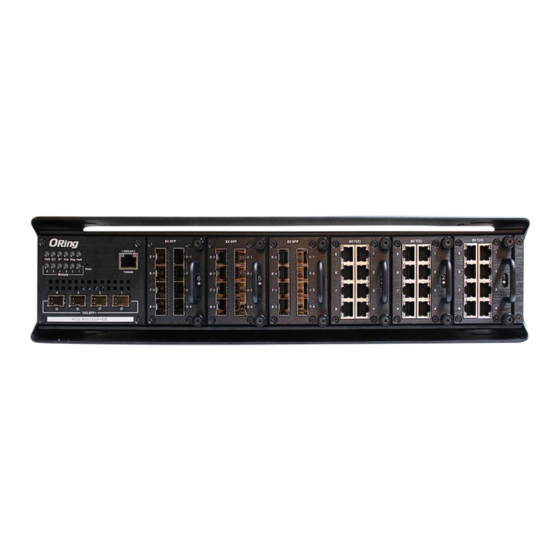
Panel Layouts
X 1
1
2 3 4 5 6 7
8
115200,8,N,1
PWR
2
1
R.M.
Ring
Fault
9
Reset
6
5
4
3
2
1
Console
Module
4
3
2
1
10
11
10G SFP+
RGS-R9004GP+ME
1. Power LED
2. Power2 LED
3. Power1 LED
4. R.M. status LED
2
1907-200-RR9004+MH1-FX010
115200,8,N,1
Reset
Console
2
1
Front View
12
5. Ring status LED
9. Module status LEDs
6. Faulty relay indicator
10. 1G/10GBase-X SFP+ ports
7. Reset button
11. Link/Act LED for SFP+ ports
8. Console port
12. Ethernet module slots
Rear View
1. Power input module slots
2. AC power input
1
PRINTED ON RECYCLED PAPER
Industrial Layer 3 modular rack mount
Managed Gigabit Switch
Installation
Rack-mounting
Step 1: Install left and right front mounting brackets to the switch using 6 M3 screws on each side
provided with switch.
Step 2: With front brackets orientated in front of the rack, nest front and rear brackets
together. Fasten together using remaining M4 screws into counter sunk holes.
Step 3: Fasten the front mounting bracket to the front of the rack.
Network Connection
The series have standard Ethernet ports. According to the link type, the switch uses CAT 3, 4, 5, 5e
UTP cables to connect to any other network devices (PCs, servers, switches, routers, or hubs).
Please refer to the following table for cable specifications.
Cable Types and Specifications:
Cable
Type
Max. Length
Connector
10BASE-T
Cat. 3, 4, 5 100-ohm
UTP 100 m (328 ft)
RJ-45
100BASE-TX
Cat. 5 100-ohm UTP
UTP 100 m (328 ft)
RJ-45
1000BASE-T
Cat. 5 / Cat. 5e 100-ohm UTP
UTP 100 m (328 ft)
RJ-45
With 10/100BASE-T(X) cables, pins 1 and 2 are used for transmitting data. and pins 3 and 6
are used for receiving data. The device also supports auto MDI/MDI-X operation. You can use
a cable to connect the switch to a PC.
For pin assignments for different types of cables, please refer to the following tables.
1000 Base-T RJ-45
10/100 Base-T(X) RJ-45
Pin Number
Assignment
Pin Number
Assignment
1
BI_DA+
1
TD+
2
BI_DA-
2
TD-
3
BI_DB+
3
RD+
4
BI_DC+
4
Not used
5
BI_DC-
5
Not used
6
BI_DB-
6
RD-
7
BI_DD+
7
Not used
8
BI_DD-
8
Not used
1000Base-T MDI/MDI-X
10/100 Base-T(X) MDI/MDI-X
Pin Number MDI port MDI-X port
Pin Number
MDI port
MDI-X port
1
BI_DA+
BI_DB+
1
TD+(transmit) RD+(receive)
2
BI_DA-
BI_DB-
2
TD-(transmit)
RD-(receive)
3
BI_DB+
BI_DA+
3
RD+(receive) TD+(transmit)
4
BI_DC+
BI_DD+
4
Not used
Not used
5
BI_DC-
BI_DD-
5
Not used
Not used
6
BI_DB-
BI_DA-
6
RD-(receive)
TD-(transmit)
7
BI_DD+
BI_DC+
7
Not used
Not used
8
BI_DD-
BI_DC-
8
Not used
Not used
Console cable
PC pin out (male)
To connect the console port to an external
assignment
management device, you need an RJ-45
Pin #2 RD
to DB-9 cable, which is also included in
the package. Please see the table for the
Pin #3 TD
console port pin assignment information.
Pin #5 GND
RS-232 baud rate setting: 9600, 8, N, 1
Quick Installation Guide
Version 1.0
RS-232 with DB9
DB9 to RJ 45
female connector
Pin #2 TD
Pin #2
Pin #3 RD
Pin #3
Pin #5 GND
Pin #5
Advertisement

Subscribe to Our Youtube Channel
Related Manuals for ORiNG RGS-R9004GP+ME-HV


Summary of Contents for ORiNG RGS-R9004GP+ME-HV
- Page 1 Introduction Installation Rack-mounting RGS-R9004GP+ME-HV is Layer-3 modular managed redundant ring Circuit Overloading: Consideration should be given to the connection of the equipment to the supply circuit and the effect that overloading of the circuits might have on overcurrent protection Ethernet switch with 6 slots, up to 48 ports, and has 4 fixed 10G SFP+ ports.
- Page 2 SMTP Client should see the following screen. For more information on configurations, please refer NTP server Modbus TCP to the user manual. For information on operating the switch using ORing’s Open-Vision management utility, please go to ORing website. O-Ring O-Chain...
Need help?
Do you have a question about the RGS-R9004GP+ME-HV and is the answer not in the manual?
Questions and answers