Table of Contents
Advertisement
Quick Links
YASKAWA AC Drive Option
CC-Link
Installation Manual
Type: SI-C3
To properly use the product, read this manual thoroughly and retain
for easy reference, inspection, and maintenance. Ensure the end user
receives this manual.
安川インバータ オプション
CC-Link
取扱説明書
形式
SI-C3
製品を安全にお使いいただくために,本書を必ずお読みください。
また,本書をお手元に保管していただくとともに,最終的に本製品をご使用になる
ユーザー様のお手元に確実に届けられるよう,お取り計らい願います。
MANUAL NO. TOBP C730600 83C
通信
Advertisement
Table of Contents

Subscribe to Our Youtube Channel
Related Manuals for YASKAWA CC-Link


Summary of Contents for YASKAWA CC-Link
- Page 1 YASKAWA AC Drive Option CC-Link Installation Manual Type: SI-C3 To properly use the product, read this manual thoroughly and retain for easy reference, inspection, and maintenance. Ensure the end user receives this manual. 安川インバータ オプション CC-Link 通信 取扱説明書 形式 SI-C3 製品を安全にお使いいただくために,本書を必ずお読みください。...
- Page 2 Yaskawa. No patent liability is assumed with respect to the use of the information contained herein. Moreover, because Yaskawa is constantly striving to improve its high-quality products, the information contained in this manual is subject to change without notice.
-
Page 3: Table Of Contents
7 BASIC FUNCTIONS ......35 8 CC-LINK DATA TABLE ......38 9 TROUBLESHOOTING . -
Page 4: Preface And Safety
Any warnings provided by YASKAWA must be promptly provided to the end user. YASKAWA offers an express warranty only as to the quality of its products in conforming to standards and specifications published in the manual. NO OTHER WARRANTY, EXPRESS OR IMPLIED, IS OFFERED. - Page 5 Energy-Saving Unit: YASKAWA D1000 Series Power Regenerative Converter Registered Trademarks • CC-Link is a registered trademark of the CC-Link Partner Association. • Other company names and product names listed in this manual are registered trademarks of those companies. Supplemental Safety Information Read and understand this manual before installing, operating, or servicing this option.
- Page 6 • The products and specifications described in this manual or the content and presentation of the manual may be changed without notice to improve the product and/or the manual. • Contact Yaskawa or a Yaskawa representative and provide the manual number shown on the front cover to order new copies of the manual.
- Page 7 Do not attempt to modify or alter the drive or drive circuitry in any way not explained in this manual. Failure to comply could cause death or serious injury and will void warranty. Yaskawa is not responsible for any modification of the product made by the user. Do not modify this product.
-
Page 8: Overview
≥9010 <1> Refer to “PRG” on the drive nameplate for the software version number. <2> Before you install the option on a YASKAWA D1000 Series Power Regenerative Converter, make sure that the option software version is PRG: 0106 or later. -
Page 9: Receiving
Refer to Figure 2 on page for details. Contact the distributor where the option was purchased or contact Yaskawa or a Yaskawa representative about any problems with the option. Contents and Packaging Table 2 Contents of Package... -
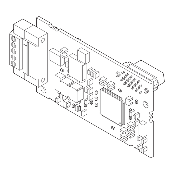
Page 10: Option Components
Figure 2 Option Card Option Modular Connector Table 3 Option Terminal Descriptions Terminal Terminal Description Communication Data + Communication Data – Signal Ground Shield Shield YASKAWA ELECTRIC TOBP C730600 83C YASKAWA AC Drive Option SI-C3 Installation Manual... - Page 11 • During reset Sending data Sending data Note: LED may appear to flash with slower baud rates. • No data being sent No data transfer • During reset YASKAWA ELECTRIC TOBP C730600 83C YASKAWA AC Drive Option SI-C3 Installation Manual...
- Page 12 Set drive parameter F6-10 to a station address (Range 1 to 64) unique to the network. If set to 0, the L.ERR light will turn on and a Station Address Error (AEr) will occur. YASKAWA ELECTRIC TOBP C730600 83C YASKAWA AC Drive Option SI-C3 Installation Manual...
-
Page 13: Installation Procedure
Do not remove covers or touch circuit boards while the drive is energized. Failure to comply could cause death or serious injury. YASKAWA ELECTRIC TOBP C730600 83C YASKAWA AC Drive Option SI-C3 Installation Manual... - Page 14 Failure to comply could prevent proper operation and damage equipment. Confirm that all connections are correct after installing the option and connecting peripheral devices. Failure to comply could damage the option. YASKAWA ELECTRIC TOBP C730600 83C YASKAWA AC Drive Option SI-C3 Installation Manual...
- Page 15 Procedures for Installing and Product Series Page Wiring Options on a Drive A1000 Procedure A D1000 Procedure A U1000 Procedure A Z1000U Procedure A GA700 Procedure B GA800 Procedure B YASKAWA ELECTRIC TOBP C730600 83C YASKAWA AC Drive Option SI-C3 Installation Manual...
- Page 16 F – Drive terminal cover G – Removable tabs for wire N – Connector CN5-C routing (Not available for communication option H – Included screws installation.) Figure 5 Drive Components with Option YASKAWA ELECTRIC TOBP C730600 83C YASKAWA AC Drive Option SI-C3 Installation Manual...
- Page 17 NOTICE: Damage to Equipment. Observe proper electrostatic discharge (ESD) procedures when handling the option, drive, and circuit boards. Failure to comply could cause ESD damage to circuitry. Figure 6 Figure 6 Remove the Keypad, Front Cover, and Terminal Cover YASKAWA ELECTRIC TOBP C730600 83C YASKAWA AC Drive Option SI-C3 Installation Manual...
- Page 18 Insert the option card (B) into the CN5-A (L) connector on the drive and fasten it into place using one of the included screws (H). Tighten the screw to 0.5 to 0.6 Nm (4.4 to 5.3 inlb). Figure 8 Figure 8 Insert the Option YASKAWA ELECTRIC TOBP C730600 83C YASKAWA AC Drive Option SI-C3 Installation Manual...
- Page 19 Note: The drive has only two ground terminal screw holes (K). Two ground wires should share the same ground terminal when connecting three options. Figure 10 SI-T3 Figure 10 Connecting the Ground Terminal YASKAWA ELECTRIC TOBP C730600 83C YASKAWA AC Drive Option SI-C3 Installation Manual...
- Page 20 2. Connect the terminator (model No.: JEPMC-W6022-E) to the option modular connector (CN1) on the end drive of the communication lines. Figure 11 Figure 11 Wire Routing Examples YASKAWA ELECTRIC TOBP C730600 83C YASKAWA AC Drive Option SI-C3 Installation Manual...
- Page 21 NOTICE: Do not pinch cables between the front covers and the drive. Failure to comply could cause erroneous operation. Figure 12 A1000 Figure 12 Replace the Front Covers and Keypad Set drive parameters in Table 7 for correct option performance. YASKAWA ELECTRIC TOBP C730600 83C YASKAWA AC Drive Option SI-C3 Installation Manual...
- Page 22 K – Connector CN5-C (Not available for communication F – Keypad option installation.) G – Option modular connector CN1 H – LED Status Ring board Figure 13 Drive Components with Option YASKAWA ELECTRIC TOBP C730600 83C YASKAWA AC Drive Option SI-C3 Installation Manual...
- Page 23 50 Vdc. When all indicators are OFF, measure for unsafe voltages to confirm the drive is safe. Affix the LED label (E) in the appropriate position on the drive front cover (D). Figure 14 Figure 14 Affix the LED Label YASKAWA ELECTRIC TOBP C730600 83C YASKAWA AC Drive Option SI-C3 Installation Manual...
- Page 24 Insert the keypad connector tab into the holder when installing the keypad connector to the holder. Holder Keypad connector tab Keypad connector Figure 15 Remove the Front Cover and Keypad YASKAWA ELECTRIC TOBP C730600 83C YASKAWA AC Drive Option SI-C3 Installation Manual...
- Page 25 NOTICE: Do not remove the LED Status Ring board cable connector. Failure to comply could cause erroneous operation and damage the drive. Figure 16 Temporary placement holes Drive front view Figure 16 Remove the LED Status Ring Board YASKAWA ELECTRIC TOBP C730600 83C YASKAWA AC Drive Option SI-C3 Installation Manual...
- Page 26 Refer to Communication Cable Topology on page 30 for details. Note: Maximum transmission distance is 100 m (328 ft). Minimum wiring distance between stations is 0.2 m (7.9 in). YASKAWA ELECTRIC TOBP C730600 83C YASKAWA AC Drive Option SI-C3 Installation Manual...
- Page 27 At that time, insert the keypad connector tab into the drive. Keypad connector Figure 18 Replace the Front Cover and Keypad Set drive parameters in Table 7 for correct option performance. YASKAWA ELECTRIC TOBP C730600 83C YASKAWA AC Drive Option SI-C3 Installation Manual...
- Page 28 Communication Cable Specifications Use only CC-Link dedicated communication cable; the Yaskawa warranty does not cover other cable types. For more information on cables, refer to the CC-Link website at http:// www.cc-link.org/. Yaskawa recommends using CC-Link cables suitable for the conditions listed in...
- Page 29 The ground wire is not necessary for installation on GA700 or GA800 drives. Figure 21 CC-Link cable Master CC-Link Drive device Option <2> <3> CC-Link Drive Option <3> <1> Termination resistor Drive CC-Link Option <3> Figure 21 Using multiple drives YASKAWA ELECTRIC TOBP C730600 83C YASKAWA AC Drive Option SI-C3 Installation Manual...
- Page 30 Figure 22 Connect Cable Wiring Take proper precautions to ensure that each cable is properly connected, and that wire insulation is not accidentally pinched into the option modular connector CN1. YASKAWA ELECTRIC TOBP C730600 83C YASKAWA AC Drive Option SI-C3 Installation Manual...
- Page 31 When the CC-Link Option is the last station connected in a CC-Link network, the termination resistor needs to be installed on that CC-Link Option. Cut the ring lugs from the termination resistor leads, and then loosen the DA and DB terminals and insert the termination resistor between terminals DA and DB as shown.
-
Page 32: Related Drive Parameters
Selects the condition for external fault Comm External Fault detection (EF0). Default: 0 F6-02 (EF0) Detect 0: Always detected. Range: 0, 1 1: Detection during run only YASKAWA ELECTRIC TOBP C730600 83C YASKAWA AC Drive Option SI-C3 Installation Manual... - Page 33 4: 10 Mbps Enables or disables the Option CC-Link bUS Error Auto Communication Error Auto Reset. Default: 0 F6-14 Reset 0: Disabled Range: 0, 1 1: Enabled YASKAWA ELECTRIC TOBP C730600 83C YASKAWA AC Drive Option SI-C3 Installation Manual...
- Page 34 <5> The setting range for 1000-Series drives is different for different software versions. Refer to the instruction manual of a specific drive for more information. <6> The default setting is 2.0 s, but this default setting will automatically be changed to 0.0 s when CC-Link option is connected.
-
Page 35: Basic Functions
Switch the RYC signal on. Data for the monitor code is stored in the PLC’s buffer memory. Note: Refer to the instruction manual for the drive the CC-Link Option is connected to for a list of monitor codes and drives. - Page 36 PLC, set the MEMOBUS register number 1000H or later to the register number 0C00H to 0C0FH from the CC-Link communications. The user can access the value of the parameters 1000H or later specified by the MEMOBUS register number 0C00H to 0C0FH with the register number 0C80H to 0C8FH.
- Page 37 4. Set the command code (1C88H) to remote register RW 5. Switch on the RYF signal (request to execute the command code). The parameter value of register number 1500H is stored in remote register RW YASKAWA ELECTRIC TOBP C730600 83C YASKAWA AC Drive Option SI-C3 Installation Manual...
-
Page 38: Cc-Link Data Table
Monitor Reference RYC needs to be turned off and register RW then back on again after the monitor code has been changed. YASKAWA ELECTRIC TOBP C730600 83C YASKAWA AC Drive Option SI-C3 Installation Manual... - Page 39 EEPROM used for the drive 100,000 times. Do not use this write command frequently. 2. Although RYE and RYF are triggered by the rising edge of the signal, they are otherwise enabled depending on the value that is input. YASKAWA ELECTRIC TOBP C730600 83C YASKAWA AC Drive Option SI-C3 Installation Manual...
- Page 40 CC-Link device Data is stored in remote register Monitoring Motor ON: Currently monitoring motor Revolutions revolutions. ON: Monitor data has been Obtain Monitor Data – updated. YASKAWA ELECTRIC TOBP C730600 83C YASKAWA AC Drive Option SI-C3 Installation Manual...
- Page 41 H1-06 = F: Through Mode Terminal S7 Function Multi-Function Input: H1-07 H1-07 = F: Through Mode H1-08 = 8: Baseblock command Terminal S8 Function Multi-Function Input: H1-08 (N.O.) Reserved – – YASKAWA ELECTRIC TOBP C730600 83C YASKAWA AC Drive Option SI-C3 Installation Manual...
- Page 42 Model of the Drive on page 46 for information on terminals. Note: Although RYF is triggered by the rising edge of the signal, they are otherwise enabled depending on the value that is input. YASKAWA ELECTRIC TOBP C730600 83C YASKAWA AC Drive Option SI-C3 Installation Manual...
- Page 43 Error – – Power Supply Undervoltage RX12 – – (AUv) RX13 Reserved – – to 19 ON: Fault occurred on the RX1A Error – energy-saving unit side. YASKAWA ELECTRIC TOBP C730600 83C YASKAWA AC Drive Option SI-C3 Installation Manual...
- Page 44 Sets data contents with RYB (Motor RXB (actual motor Output Frequency Revolutions/Output Frequency Switch). rotations) Set in the drives specified by o1-03 (Frequency Reference Setting Drives) in output frequency. YASKAWA ELECTRIC TOBP C730600 83C YASKAWA AC Drive Option SI-C3 Installation Manual...
- Page 45 Table 16 Remote Register (Energy-Saving Unit → PLC) Remote Name Description Check Flag Register Monitor data is stored according to RW Monitor Data RXC (while monitoring) (Monitor Code). Reserved – – YASKAWA ELECTRIC TOBP C730600 83C YASKAWA AC Drive Option SI-C3 Installation Manual...
- Page 46 All drives Output 2 YASKAWA AC Drive P1-C1 CIPR-GA70A, CIPR-GA70T Multi-Function Digital GA700 CIPR-GA70U, CIPR-GA70C, CIPR-GA70B, Output 3 M5-M6 CIPR-GA70K, CIPR-GA70D Multi-Function Digital P2-C2 CIPR-GA70A, CIPR-GA70T Output 4 YASKAWA ELECTRIC TOBP C730600 83C YASKAWA AC Drive Option SI-C3 Installation Manual...
- Page 47 Refer to the drive instruction manual for details. <2> Terminals will change to M5-M6 depending on the model type of CIMR-B. Refer to the drive instruction manual for details. YASKAWA ELECTRIC TOBP C730600 83C YASKAWA AC Drive Option SI-C3 Installation Manual...
-
Page 48: Troubleshooting
Both bUS (CC-Link Option Communication Error) and EF0 (Option Card External Fault from the CC-Link Option) can appear as an alarm or as a fault. When a fault occurs, the keypad ALM LED remains. When an alarm occurs, the keypad ALM LED flashes. - Page 49 2. Make sure that the option is correctly connected to the connector. option. 3. If the problem continues, replace the option. Keypad Display Fault Name Option Card Connection Error (CN5-A) oFA30 to oFA43 Communication ID error. YASKAWA ELECTRIC TOBP C730600 83C YASKAWA AC Drive Option SI-C3 Installation Manual...
- Page 50 Option Flash write mode. Cause Possible Solution An option of the same type is already installed in option Connect the option to the correct option port. port CN5-A, CN5-B, or CN5-C. YASKAWA ELECTRIC TOBP C730600 83C YASKAWA AC Drive Option SI-C3 Installation Manual...
- Page 51 Note: If the option software version is not compatible or if you install communication option an incorrect option to the drive, it will trigger an alarm. parameters. YASKAWA ELECTRIC TOBP C730600 83C YASKAWA AC Drive Option SI-C3 Installation Manual...
- Page 52 Figure 27 Station 1 Drive Power Master supply device CC-Link Option Figure 27 Connecting a Single Drive YASKAWA ELECTRIC TOBP C730600 83C YASKAWA AC Drive Option SI-C3 Installation Manual...
- Page 53 9 Troubleshooting Table 20 LED Fault Display for CC-Link Option with a Single Drive : On / : Flashing / ×: Off / ∗: Either on or off L.RUN L.ERR Cause Possible Solution × Normal communications –...
- Page 54 Station 3 Station 1 Station 2 Drive Drive Drive Power Master supply device CC-Link CC-Link CC-Link Option Option Option Figure 28 Connecting Multiple Drives on the Same Network YASKAWA ELECTRIC TOBP C730600 83C YASKAWA AC Drive Option SI-C3 Installation Manual...
- Page 55 9 Troubleshooting Table 21 LED Fault Display for CC-Link Option with Multiple Drives : On / : Flashing / ×: Off / ∗: Either on or off LED Status Remote Device Addresses Cause Corrective Action (CC-Link Option) Master Station 1...
- Page 56 Configure the final station Termination resistor not SD SD SD connected in the series with a RD RD RD (L.RUN is sometimes off). termination resistor. L.ERR× L.ERR× L.ERR YASKAWA ELECTRIC TOBP C730600 83C YASKAWA AC Drive Option SI-C3 Installation Manual...
-
Page 57: European Standards
Keep wiring as short as possible and ground the largest possible surface area of the shield to the metal panel according to Figure YASKAWA ELECTRIC TOBP C730600 83C YASKAWA AC Drive Option SI-C3 Installation Manual... - Page 58 Cable clamp I/O option I/O device CN5-A, CN5-B, CN5-C Cable clamp Communication Master option CN5-A Figure 31 Option Installation for CE Compliance (PG-, DI-, DO-, AI-, AO-, SI-) YASKAWA ELECTRIC TOBP C730600 83C YASKAWA AC Drive Option SI-C3 Installation Manual...
-
Page 59: Specifications
Up to 1000 m (3280 ft) Note: The number of drives that can be connected to the network varies depending on the type of nodes connected. Refer to page for more information. YASKAWA ELECTRIC TOBP C730600 83C YASKAWA AC Drive Option SI-C3 Installation Manual... - Page 60 Back cover Revision: Address Revision: Applicable product series Reviewed and corrected entire documentation. <1> October 2016 Back cover Revision: Address − − April 2016 First edition YASKAWA ELECTRIC TOBP C730600 83C YASKAWA AC Drive Option SI-C3 Installation Manual...
- Page 61 Phone: +81-3-5402-4502 Fax: +81-3-5402-4580 http://www.yaskawa.co.jp YASKAWA AMERICA, INC. 2121, Norman Drive South, Waukegan, IL 60085, U.S.A. Phone: +1-800-YASKAWA (927-5292) or +1-847-887-7000 Fax: +1-847-887-7310 http://www.yaskawa.com YASKAWA ELÉTRICO DO BRASIL LTDA. 777, Avenida Piraporinha, Diadema, São Paulo, 09950-000, Brasil Phone: +55-11-3585-1100 Fax: +55-11-3585-1187 http://www.yaskawa.com.br...
Need help?
Do you have a question about the CC-Link and is the answer not in the manual?
Questions and answers