Table of Contents
Advertisement
Advertisement
Table of Contents

Related Manuals for GRAPHTEC midi LOGGER GL220


Summary of Contents for GRAPHTEC midi LOGGER GL220
- Page 1 USER’S MANUAL MANUAL NO. GL220-UM-151...
-
Page 2: Notes On Use
Notes for Safe Operation (1) Be sure to use the Graphtec-supplied AC adapter. In environments where there is a lot of noise or where the power supply is unstable, we recommend that you ground the GL220. - Page 3 Introduction (7) Insofar as possible, position the GL220 input signal cables away from any other cables which are likely to be affected by electromagnetic interference. (8) For stabilized measurement, allow the GL220 to warm up for at least 30 minutes after turning it on. About Registered Trademarks •...
-
Page 4: To Ensure Safe And Correct Use
To Ensure Safe and Correct Use To Ensure Safe and Correct Use ● To ensure safe and correct use of the GL220, read this Manual thoroughly before use. ● After having read this Manual, keep it in a handy location for quick reference as needed. ●... -
Page 5: Safety Precautions
● After checking that smoke is no longer being generated, to current leakage. contact your sales representative or nearest Graphtec ● Before running the GL220 using a DC power supply, be sure to vendor to request repair. - Page 6 Use in such status may cause a fire hazard due to electrical electrical shock or a fire hazard. shock or current leakage. ● Contact your sales representative or nearest Graphtec vendor to request repair. Unplug the power Use prohibited cord from the socket Do not attempt to lubricate the GL220’s mechanisms.
-
Page 7: Table Of Contents
CONTENTS CONTENTS Introduction ................................. I Notes on Use ............................I About Registered Trademarks ......................II To Ensure Safe and Correct Use ........................i Conventions Used in This Manual ....................... i Description of Safety Symbols ......................i Safety Precautions ............................ii 1 General Description .................. - Page 8 CONTENTS (3) MENU ............................3-8 (4) QUIT (LOCAL) ...........................3-8 (5) Direction keys ..........................3-8 (6) ENTER ............................3-8 (7) FAST FORWARD key (KEY LOCK) ...................3-9 (8) START/STOP (USB Drive Mode) ....................3-9 (9) REVIEW ...........................3-10 (10) DISPLAY ..........................3-10 (11) CURSOR (ALARM CLEAR) ....................3-11 (12) FILE ............................3-11 Operation Modes ..........................3-13 (1) Free Running ...........................3-13 (2) Capturing ..........................3-14...
-
Page 10: General Description
CHAPTER 1 General Description This chapter provides a general description of the GL220 and its features. Overview Features Operating Environment Notes on Temperature Measurement Notes on Using the Monitor Changing the Display Language... -
Page 11: Overview
CHAPTER 1 General Description Overview The GL220 (with color monitor and internal memory) are compact, lightweight data loggers. GL220 are equipped with an Internal memory to enable the direct capture of a large volume of data to USB memory. Furthermore, the data loggers can be connected to a PC via USB to enable on-line settings, measurement, and data capture. -
Page 12: Operating Environment
CHAPTER 1 General Description Operating Environment This section explains the operating environment for the GL220 Ambient Operating Conditions (1) Ambient temperature and humidity (the GL220 must be operated within the following ranges.) • Temperature range: 0 to 45°C (0 to 40°C when battery pack is mounted) •... -
Page 13: Notes On Temperature Measurement
CHAPTER 1 General Description Notes on Temperature Measurement Please observe the following precautions when performing temperature measurement. ● Do not block the air vents. Always provide a space of at least 30 cm on all sides of the GL220. ● For stabilized temperature measurement, allow the GL220 to warm up for at least 30 minute safter turning it on. -
Page 15: Checks And Preparation
CHAPTER 2 Checks and Preparation This chapter explains how to check the GL220’s external casing and accessories, and how to prepare the GL220 for operation. Checking the Outer Casing Checking the Accessories GL220 Nomenclature and Functions Connecting the Power Cable and Turning on the Power Connecting the Signal Input Cables Connecting the External I/O Cable... -
Page 16: Checking The Outer Casing
CHAPTER 2 Checks and Preparation Checking the Outer Casing After unpacking, check the GL220’s outer casing before use. In particular, please check for the following: ● Surface scratches ● Other flaws such as stains or dirt Checking the Accessories After unpacking, check that the following standard accessories are included. Standard Accessories Item Remarks... -
Page 17: Gl220 Nomenclature And Functions
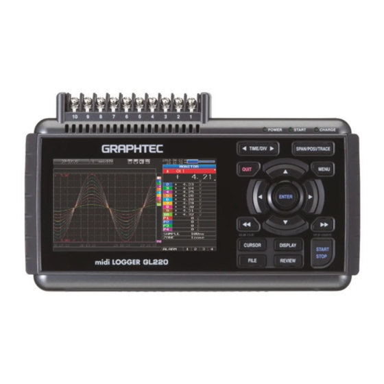
CHAPTER 2 Checks and Preparation GL220 Nomenclature and Functions This section describes the names and function of parts of the GL220. Operation status LED POWER : ON when the power is ON START : ON during data capture Monitor CHARGE : ON while the battery is charging Power switch USB I/F terminal (Right side) -
Page 18: Connecting The Power Cable And Turning On The Power
CHAPTER 2 Checks and Preparation Connecting the Power Cable and Turning on the Power This section describes how to connect the power cable and turn on the power. The connection method will vary depending on the type of power supply used. Connecting to an AC Power Supply Use the AC cable and AC adapter that are provided as accessories. -
Page 19: Connecting To A Dc Power Supply
CHAPTER 2 Checks and Preparation Connecting to a DC Power Supply Use the optional DC drive cable (B-514). Use a power supply within the 8.5 to 24 VDC range (26.4 VDC max.). (1) Configure the tip of the DC drive cable (B-514: 2m) to enable it to be connected to the DC power supply. -
Page 20: Connecting The Signal Input Cables
CHAPTER 2 Checks and Preparation Connecting the Signal Input Cables This section describes how to connect the signal input cables. Terminal Configuration and Signal Types Terminal configuration Voltage input Thermocouple input DC voltage Compensation wire is used if it is required. Current input Resistance temperature detector not available... -
Page 21: Logic Alarm Cable Connection And Functions
CHAPTER 2 Checks and Preparation Logic Alarm Cable Connection and Functions Logic Alarm Cable Connection The logic alarm cable (B-513: Option) enables logic/pulse input, external trigger input, external sampling input, and alarm signal output. Connect the logic alarm cable (B-513: Option) to the external input/output terminal as shown below. Logic alarm cable (B-513: Option) Logic/Pulse Specifications... -
Page 22: Internal Equivalent Circuit Of The Input/Output Circuit
CHAPTER 2 Checks and Preparation Internal Equivalent Circuit of the Input/Output Circuit ● Alarm Output Maximum ratings of the transistor for alarm output VCEO (Collector-emitter voltage) : 30 V IC (Collector current) : 0.5 A PC (Collector dissipation) : 0.2 W * The maximum ratings must not be exceeded. -
Page 23: Wiring
CHAPTER 2 Checks and Preparation Wiring Cable tips are bare tips. Perform wiring for the necessary functions. Signal Name Channel Number Wire Color Logic/Pulse output Orange with red dotted line Orange with black dotted line Gray with red dotted line Gray with black dotted line Alarm output White with red dotted line... -
Page 24: Attaching Usb Memory
CHAPTER 2 Checks and Preparation Attaching USB Memory Attaching USB memory to the GL220 allows you store measured data directly. Adequate precautions against static electricity must be taken when handling USB memory. Inserting a USB Memory Attach the USB memory to the USB memory port. USB Memory When you attach the USB memory to GL220A, be careful during handling so as not to bump or drop the unit. -
Page 25: Connecting To A Pc
CHAPTER 2 Checks and Preparation Connecting to a PC Use the USB cable to connect the GL220 to a PC. Connection Using a USB Cable Use the USB cable to connect the GL220 to a PC. USB cable If the USB cable is used, the USB driver must be installed in your PC. Please refer to “USB Driver Installation Manual”... -
Page 26: Using The Battery Pack (The B-517 Option)
CHAPTER 2 Checks and Preparation Using the Battery Pack (the B-517 Option) ● The B-517 battery is the only battery type that can be used with the GL220. ● Refer to the specifications (P.4-7) for information on the battery run time. ●... -
Page 27: Charging The Battery
CHAPTER 2 Checks and Preparation Charging the Battery ● Expected time required for charging: Approx. 4 hours The battery pack is charged by mounting it in the GL220, attaching AC adapter to the GL220. (1) Mount the battery pack in the GL220 (see the previous section for the mounting procedure). (2) Turn on the power to the GL220. -
Page 28: Connecting The Humidity Sensor (Option)
CHAPTER 2 Checks and Preparation 2.10 Connecting the Humidity Sensor (Option) Connect the + and - lead wires of the humidity sensor (the B-530 option) to the desired terminals, and theninsert the round connector into the 5V OUT connector on the GL220. Brown: Connected to the + terminal White: Connected to the - terminal Humidity sensor... -
Page 29: Precautions To Observe When Performing Measurement
CHAPTER 2 Checks and Preparation 2.11 Precautions to Observe When Performing Measurement Please be sure to read the following carefully in order to prevent electric shocks or shorts. • Do not apply voltage of 60Vp-p or above between the analog input section and main unit, or between analog input channels. -
Page 30: Noise Countermeasures
CHAPTER 2 Checks and Preparation 2.12 Noise Countermeasures ● Be sure to connect the chassis GND of the object to be measured. Ensure that the chassis GND wire of the measurement object is connected to a good ground. Measurement object GL220 Input terminals Thermocouple... -
Page 31: Setting The Date And Time
CHAPTER 2 Checks and Preparation 2.13 Setting the Date and Time If you are using the GL220 for the first time, charge the internal rechargeable battery and then make thedate and time settings. If the GL220 is not used for a period of approximately six months, the internal rechargeable battery may be discharged and the date and time may revert to the initial settings. -
Page 33: Settings And Measurement
CHAPTER 3 Settings and Measurement This chapter describes the setting and measurement procedures for the GL220. Window names and functions Key Operation Operation Modes Setting Menus... -
Page 34: Window Names And Functions
CHAPTER 3 Settings and Measurement Window names and functions 4. Internal memory access display 5. USB memory access display 3. Status mark 6. Remote display 1. Simplified message display 9. AC/battery status display 7. Key lock display 2. TIME/DIV 8. Clock display 19. - Page 35 CHAPTER 3 Settings and Measurement 2. Time/DIV display Displays the current time scale. 3. Status mark : Appears when neither capture nor replay is in progress. *: Appears when data is being captured in the internal memory or USB memory. *: Appears when waiting for a trigger during capturing and the stop key after capturing.
- Page 36 CHAPTER 3 Settings and Measurement 8. Clock display Displays the current date and time. Refer to page 3-35 for details on setting the date and time. 9. AC/battery display : Running on AC or DC power supply. : Running on the battery. The remaining battery power is 100 to 91%. : Running on the battery.
- Page 37 CHAPTER 3 Settings and Measurement 14. Time stamp Displays the time stamp of a currently displayed waveform as time. This indicator shows that the measurement data was captured at 15:26:49. 15. File name display (1) During data capture A capture file name is displayed during capture. * If the ring capture setting is ON, a file name displayed during capture ends with "_RINGx"...
- Page 38 CHAPTER 3 Settings and Measurement 19. Data capture bar (1) During data capture Displays the elapsed time and the memory usage status. Elapsed time Remaining time for data capture Amount of memory used Amount of memory remaining Total amount of memory If, for example, 256 MB USB memory is inserted and about 96 MB is used before data capture, the total amount of memory is 256 MB, the amount of memory used is about 96 MB, and the amount of memory remaining is about 160 MB.
-
Page 39: Key Operation
CHAPTER 3 Settings and Measurement Key Operation This section describes key operation. (1) SPAN/TRACE/POSITION (2) TIME/DIV (3) MENU (4) QUIT (5) Direction Keys (6) ENTER (7) FAST FORWARD key (KEY LOCK) (11) CURSOR (8) START/STOP (USB DRIVE) (ALARM CLEAR) (12) FILE (10) DISPLAY (9) REVIEW (1) SPAN/TRACE/POSION... -
Page 40: Time/Div
CHAPTER 3 Settings and Measurement (2) TIME/DIV Press the left/right key of the TIME/DIV key to change the time axis display width. (3) MENU Open the settings window to capture data. For details on settings, see “3.4 Setting Menus” on page 3-16. (4) QUIT (LOCAL) This key is primarily used for the following operations. -
Page 41: Fast Forward Key (Key Lock)
CHAPTER 3 Settings and Measurement (7) FAST FORWARD key (KEY LOCK) This key is primarily used for the following operations. • To move the cursor at high speed during replay. • To change the operation mode in the file box. •... -
Page 42: Review
CHAPTER 3 Settings and Measurement (9) REVIEW This key is used to replay captured data. • During Free Running, replays captured data. The screen used to specify the data replay source file appears; specify the file you want to replay. •... -
Page 43: Cursor (Alarm Clear)
CHAPTER 3 Settings and Measurement (11) CURSOR (ALARM CLEAR) • This key is used to toggle between cursors A and B during replay. cursor B cursor A cursor B cursor A The selected cursor turns white, and the other one turns gray. •... - Page 44 CHAPTER 3 Settings and Measurement Basic Procedures Used in Settings The following are basic operation procedures for settings. 1. Press the MENU key to open each menu. 2. Use the key to move the cursor to the items you want to set. 3.
-
Page 45: Operation Modes
CHAPTER 3 Settings and Measurement Operation Modes You can check the system operation status in the simplified message display. operation operation simplified message display Free Running Start up status or data is not being captured Free Running Capturing Data is being captured in the main memory Memory Recording or USB memory. -
Page 46: Capturing
CHAPTER 3 Settings and Measurement (2) Capturing Capture time Note: “+++++:++:++” is displayed when the capture time is long. Time of Capturing Capture file name During data capture, data is captured into the Internal memory or USB device. You cannot use the MENU key to change the setting. Operations available during capture SPAN/TRACE/POSITION The SPAN/TRACE/POSITION key is used to change settings. -
Page 47: Replaying
CHAPTER 3 Settings and Measurement (4) Replaying Displays the voltage at a point indicated by Cursor A or B or the selected cursor. Displays the measurement time at a point indicated by Cursor A or B or the selected cursor. Displays the captured data. -
Page 48: Setting Menus
CHAPTER 3 Settings and Measurement Setting Menus When you press the MENU key during Free Running, the following menu screens appear. The menu screens are classified by the tab for each setting item. DATA TRIG USER OTHR (1) AMP settings This menu is used to specify input signal-related settings. - Page 49 CHAPTER 3 Settings and Measurement Switching displays Analog and logic/pulse can be switched as shown below. ▪ Display Logic/Pulse Data ▪ Display Analog Data Analog settings Specify the conditions for analog signals. When you use CH ALL to set an input, range and filter, all channels are set to the same values if the input is the same. Range is set only for the same input channels.
- Page 50 CHAPTER 3 Settings and Measurement <Temperature Ranges> Range Maximum SPAN Minimum SPAN (p-p) Measurement Minimum Resolution Range -270 to +2000°C 50°C -200 to +1370°C -270 to +2000°C 50°C -200 to +1100°C -270 to +2000°C 50°C -200 to +400°C -270 to +2000°C 50°C 0 to +1600°C -270 to +2000°C...
- Page 51 CHAPTER 3 Settings and Measurement (1)-4 EU (Scaling settings) Converts the measured signals to other units. <For voltage input> <For temperature input> Setting Description (1) EU Function Sets the scaling function to ON or OFF. (2) Meas. Value (Upper/ Sets the upper and lower limits of values to be converted. Lower) * For temperature input, there is no distinction between upper and lower limits.
- Page 52 CHAPTER 3 Settings and Measurement (1)-5 Misc. Setting Description (1) Inter-CH Op Settings Sets what to do in calculation between channels. Four arithmetic operations (+, -, x, ÷) can be set as calculation between channels. * Refer to the next page for details. (2) Span Sets the upper and lower limits of values of a span in which a waveform should be dis- played.
- Page 53 CHAPTER 3 Settings and Measurement Logic and Pulse settings Makes settings related to digital input. <For Pulse> <For Logic> (1)-6 Logic/Pulse Selects the processing method for digital input. Selection item Description Digital input measurement is disabled. Logic Digital input is processed as logic signals. Pulse Digital input is processed as pulse signals.
- Page 54 CHAPTER 3 Settings and Measurement (1)-10 EU (Scaling settings) Converts the measured signals to other units. This setting is available only if Pulse is selected in (1)-7. Setting Description (1) EU Setting Sets the scaling function to ON or OFF. (2) Meas.
- Page 55 CHAPTER 3 Settings and Measurement (2) DATA settings This menu is used to specify capture-related items and calculations. Setting Selections available Sampling 10, 20, 50, 100, 125, 200, 250, 500 ms; 1, 2, 5, 10, 20, 30s; 1, 2, 5, 10, 20, 30 min;...
- Page 56 Example: TEST_CP1.GBD (4) File Type Sets the file format used to save data. GBD : Creating a data file in Graphtec's proprietary binary format * Data tampering can be prevented. CSV : Creating a data file in text format * Replaying on the GL220 is not available.
- Page 57 CHAPTER 3 Settings and Measurement ●Ring Capture Function Ring-captur has been operating in this instrument is as follows. Start capturing data Captured data is saved into the File 1. When the specified number of datas are saved into the File 1, the captured data is saved into the File 2. The number of data is specified in the “Ring Capture Points”...
- Page 58 CHAPTER 3 Settings and Measurement (2)-3 External sampling Enables or disables external sampling. When the external sampling function is enabled, data is captured at the shortest intervals and retained temporarily. This retained data is updated at the shortest intervals. When an external sampling pulse is received, the retained data is written to the memory. (See the following figure.) Therefore, the maximum error in time between the actually captured data and the external sampling pulse is the same as the shortest interval.
- Page 59 Save folder Sets the folder for saving a backup file. * This must be a folder on USB memory or an FTP server. Example: \GRAPHTEC\20091205 * If ring capture is On, the backup function is not available. (2)-6 Statistical calculation setting Two types of operation can be performed on all channels.
- Page 60 CHAPTER 3 Settings and Measurement (3) TRIG settings This menu is used to specify trigger conditions and alarms. Setting Selections available Start Side Source Setting Off, Level, Alarm, External Input, Time, Day, Duration [Level] Mode Analog: Off, ↑ H, ↓ L, Window In, Window Out Logic: Off, ↑...
- Page 61 CHAPTER 3 Settings and Measurement (3)-2 Stop side source setting Specifies trigger conditions to stop data capture. Selection item Description Stops capturing data unconditionally when you press the Start/Stop key. Level Stops capturing data when a specified level is reached. ->...
- Page 62 CHAPTER 3 Settings and Measurement Trigger level settings/Alarm level settings Specifies detailed conditions for each channel when the start and stop side source settings are Level. The configuration of the level trigger is as shown in the figure below. Mode Mode CH n Level...
- Page 63 CHAPTER 3 Settings and Measurement Level and Edge operations In the Level operation, a trigger is assumed to be generated if the trigger conditions are met when the START key is pressed. In the Edge operation, a trigger is not assumed to be generated even if the trigger conditions are met when the START key is pressed.
- Page 64 CHAPTER 3 Settings and Measurement Dead zones of trigger and alarm levels Trigger and alarm levels are provided with a dead zone in order to prevent false detection due to noise. Since a dead zone exists as shown in the figure below, the conditions are met at different points between rising and falling signals.
- Page 65 CHAPTER 3 Settings and Measurement (4)-1 USER settings Setting Description User Specify the user name. You cannot specify it as Guest. Department name Specify the department name. You cannot specify it as Guest. Setting conditions Switches between Guest, User1 and User2. switch Since setting conditions are stored for each user, they can be called up easily by simply switching the user.
- Page 66 CHAPTER 3 Settings and Measurement (5) OTHR settings Other miscellaneous settings are made here. Setting Selections available LCD brightness Light, Medium, Dark Screen Saver Off, 10, 30 (sec.), 1, 2, 5, 10, 30, 60 (min.) Power On Start Disable, Enable Background Color Black, White AC Line Frequency...
- Page 67 CHAPTER 3 Settings and Measurement (5)-4 Background Color Sets the background colors of the waveform display area and the digital display area. (5)-5 AC Line Frequency Select the frequency of the AC line used. Selection item Description 50Hz For an area with a power supply frequency of 50 Hz 60Hz For an area with a power supply frequency of 60Hz In this setting, select a frequency for noise removal using the digital filter.
- Page 68 CHAPTER 3 Settings and Measurement (5)-10 Return to default settings Returns all the settings to the factory defaults. (5)-11 Information Displays system information. (5)-12 Demo Waveform Mode This parameter displays demo waveforms without analog signal input. Selection item Description The demo waveform is not displayed. The demo waveform is displayed.
- Page 69 (3) File Type Sets the file format used to save data. GBD: Creating a data file in Graphtec's proprietary binary format * Data tampering can be prevented. CSV: Creating a data file in text format * Replaying on the GL220 is not available.
- Page 70 CHAPTER 3 Settings and Measurement (6)-3 Remove/Exchange USB Memory The GL220 allows you to exchange the USB memory while data is captured to it. Exchange the USB memory in accordance with the following procedure: (1) Press the FILE key to open the FILE menu. (2) Move the cursor to Remove/Exchange USB Memory and press the ENTER key.
- Page 71 CHAPTER 3 Settings and Measurement (5) After checking that the USB memory access display turns green, press the ENTER key. Refer to page 3-3 for details on USB memory access. “_CHG” and a number will be appended to the file name each time you exchange a USB memory device. Example: When data is captured to the file “TEST.GBD”: First USB memory device : TEST.GBD...
- Page 72 CHAPTER 3 Settings and Measurement (6)-6 Save Saves the setting conditions of the GL220. <If the naming method is Auto> <If the naming method is Arbitrary> Setting Description (1) Folder Specify a folder to which you want to save data. Refer to page 3-41, "File box" for details. (2) File Specify a file to which you want to save data.
- Page 73 CHAPTER 3 Settings and Measurement (7) File box The file box used to set captured data files using the DATA menu or for disk operations accessed using the FILE menu is operated as follows. <File box by disk operations> Description Change the operation of the file box.
- Page 74 CHAPTER 3 Settings and Measurement Use the key to move to the target folder. Use the key to select [Create new folder]. Press the ENTER key. When the input box for a new folder name opens, enter "TEST" and click OK. Use the key to choose [Select file/folder].
- Page 75 CHAPTER 3 Settings and Measurement (8) Text input Related to text input operations such as annotation, EU (scaling) unit and captured data file name input. • Operation Operation mode Description Operation method Text input Upper case alphabet mode When the cursor key is moved to the uppermost part, operation can Lower case alphabet mode be selected using the left/right key.
- Page 76 CHAPTER 3 Settings and Measurement (9) Data replay menu Data replay menus are displayed by pressing the MENU key during replay. Setting Selections available Cursor Move to First Data Press right key to execute. Position Move to Last Data Press right key to execute. Move to Center Press right key to execute.
- Page 77 CHAPTER 3 Settings and Measurement (9)-4 Move to Selected Position Sets a position (relative position in time) or time and moves the currently selected cursor (A or B) to this position or time. <If the Method is Position> <If the Method is Time> Setting Selections available (1) Method...
- Page 78 CHAPTER 3 Settings and Measurement (9)-9 Execute (Calculation) Executes calculation between cursors. Executing this option opens a window to display calculation results. For description of the calculation results, see the table below. Pressing the FILE key opens a window for saving statistical calculation results.
- Page 79 CHAPTER 3 Settings and Measurement (10) Quick settings Screen Operation mode Content Explanation Waveform Free Running SAMPLE key can be used to change the sampling interval. ZONE key can be used to change the zone division. Recording ZONE key can be used to change the zone division. Dual View Replaying ZONE key can used to change the zone division.
-
Page 81: Specification
CHAPTER 4 Specification This chapter describes the basic specifications forthe GL220. Standard Specifications Function Specifications Accessory/Option Specifications External Dimensions... -
Page 82: Standard Specifications
CHAPTER 4 Specifications Standard Specifications Standard Specifications Item Description Number of analog channel 10 channels External input/output Trigger input or external sampling pulse/logic input 4 channels or pulse input 4 channels, alarm output 4 channels PC interface USB (Full speed) standard Internal memory device Approx. -
Page 83: Internal Memory Devices
CHAPTER 4 Specifications Internal memory devices Item Description Memory capacity Internal memory : Approx. 2GB Flash Memory USB memory : Unlimited (However, one file must be 2GB at the maximum.) Memory contents • Setup conditions • Measured data • Screen copy PC Interface Item Description... -
Page 84: Input Unit Specifications
CHAPTER 4 Specifications Input Unit Specifications Item Description Number of input channels 10 channels Input terminal type M3 screw type terminal Input method Photo MOS relay scanning system All channels isolated, balanced input Scan speed 10 ms/1 ch maximum Measurement ranges Voltage: 20, 50, 100, 200, 500 mV;... -
Page 85: Function Specifications
CHAPTER 4 Specifications Function Specifications Function Specifications Item Description Display screen Waveform + Digital screen, All Waveform screen, Digital + Calculation Display screen, Expanded digital screen * Can be switched using the dedicated key (toggle operation). * For the Expanded Digital screen, the number of channels and the display channel must be specified. -
Page 86: External Input/Output Functions
CHAPTER 4 Specifications External Input/Output Functions Item Description Input/output types • Trigger input (1 ch) or External sampling input (1 ch) • Logic input (4 ch) or Pulse input (4 ch) • Alarm output (4 ch) * Switch between Logic and Pulse * Switch between Trigger and External sampling. -
Page 87: Accessory/Option Specifications
CHAPTER 4 Specifications Accessory/Option Specifications Control Software Item Description Compatible operating system Windows XP/Vista/Windows 7 Functions Main unit control, realtime data capture, data conversion, data replay Main unit settings AMP settings, Data Capture settings,Trigger Alarm settings, Report settings, Other settings Captured data Realtime data (CSV, Binary) Internal memory (CSV, Binary) -
Page 88: Humidity Sensor B-530 (Option)
CHAPTER 4 Specifications Humidity Sensor B-530 (Option) Item Description Allowable temperature range -25 to +80°C Allowable humidity range 0 to 100% RH Relative humidity measurement ±3% RH (5 to 98% RH at 25°C) accuracy Method Capacitance method Relative humidity measurement Measurement environment Measurement accuracy accuracy... -
Page 89: External Dimensions
CHAPTER 4 Specifications External Dimensions 91.6 16.5 16.1 M4 L5 insert screw Dimension precision: Error ± 5 mm Unit: mm... -
Page 91: Index
Index Index DISPLAY key ............3-10 Dual View Replaying ........3-13, 3-14 AC line filter ............3-26 AC Line Frequency ..........3-35 AC Power Supply .............2-4 Edge operations ............3-31 AC/battery display ...........3-4 ENTER key ..............3-8 Accessories ............. 2-2, 4-7 EU ..............3-19, 3-22 A/D resolution .......... - Page 92 Index Lower limit scale ............3-5 Status mark area .............3-3 Logic Alarm Cable ...........2-7 Stop side source setting ........3-29 Internal equivalent circuit of I/O ......2-8 Temp Unit ..............3-35 Macro ..............3-33 Temperature setting ..........3-35 Maximum input voltage ..........2-15 Text input ...............3-43 MENU key ...............3-8 TIME/DIV display area ..........3-3 Monitor Specifications ..........4-3 TIME/DIV key ............3-8...
- Page 93 • The specifications, etc., in this manual are subject to change without notice. GL220-UM-151 April 1, 2010 1st edition-01 GRAPHTEC CORPORATION...
- Page 94 GRAPHTEC CORPORATION 503-10 Shinano-cho, Totsuka-ku, Yokohama 244-8503, Japan Tel: +81 (045) 825-6250 Fax : +81 (045) 825-6396 Email : info@graphteccorp.com Web: www.graphteccorp.com Printed in Japan...
Need help?
Do you have a question about the midi LOGGER GL220 and is the answer not in the manual?
Questions and answers