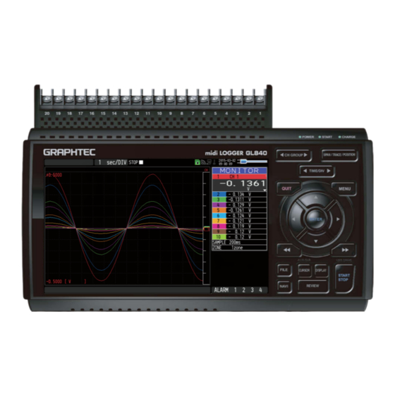
GRAPHTEC GL840 User Manual
Midi logger
Hide thumbs
Also See for GL840:
- User manual (208 pages) ,
- Quick start manual (24 pages) ,
- Quick start up manual (24 pages)
Table of Contents
Advertisement
Quick Links
Advertisement
Table of Contents

Related Manuals for GRAPHTEC GL840


Summary of Contents for GRAPHTEC GL840
- Page 1 GL840 USER’S MANUAL MANUAL NO.GL840-UM-151...
-
Page 3: To Ensure Safe And Correct Use
Conventions Used in This Manual To promote safe and accurate use of the GL840 as well as to prevent human injury and property damage, safety precautions provided in this manual are ranked into the five categories described below. Be sure you understand the difference between each of the categories. -
Page 4: Safety Precautions
• • Before running the GL840 using a DC power supply, be Use of the GL840 in such status may result in a fire hazard sure to ground the protective ground terminal ( ) to avoid or electrical shock. - Page 5 Safety Precautions Safety Precautions CAUTION Do not use or store the GL840 in a location exposed to Do not place coffee cups or other receptacles direct sunlight or the direct draft of an air conditioner containing fluid on the GL840.
- Page 6 Use prohibited Use prohibited This GL840 is not meant for use with lifesaving devices or devices with mission-critical high reliability or high safety requirements (medical devices, aerospace devices, shipping devices, nuclear power devices, etc.). In the event that this GL840 causes injury or property damage when used under these circumstances,...
-
Page 7: Introduction
Moreover, use of the GL840 by incorrect procedures may result in damage to the GL840 or may invalidate its safeguards. Please confirm all of its notes regarding use and other related information to ensure correct use. - Page 8 Introduction This GL840 is meant for use in Japan, the US, and Europe. It has not been certified for use under any other country’s radio laws. The following are each region’s certification marks. Japan Contains FCC ID: ANSBP3591 Europe..CE Mark This device complies with part 15 of the FCC Rules.
- Page 9 (6) Measured results may not conform to the stated specifications if the GL840 is used in an environment which is subject to strong electromagnetic interference. (7) Insofar as possible, position the GL840 input signal cables away from any other cables which are likely to be affected by electromagnetic interference.
-
Page 10: Notes On The Use Of This Manual
(1) All rights reserved. No part of this publication may be reproduced, stored in a retrieval system, or transmitted, in any form or by any means, without the prior written permission of Graphtec Corporation. (2) The specifications and other information in this manual are subject to change without notice. -
Page 11: Table Of Contents
CONTENTS CONTENTS To Ensure Safe and Correct Use ..........Safety Precautions . - Page 12 Monitor ..............Standard terminal input section (GL840-M and B-564) ......
- Page 13 CONTENTS Accessories/Optional Accessories ........4-10 4-10 Control Software .
-
Page 15: Chapter 1 General Description
CHAPTER 1 General Description CHAPTER 1 General Description This chapter provides a general description of the GL840 and its features. PRODUCT SUMMARY Overview Features Operating Environment Notes on Temperature Measurement Notes on Using the Monitor Changing the Display Language... -
Page 16: Overview
100 msec and higher.) • The GL840 is equipped with the relay recording function, and 2GByte or more data can be saved by switching the to the other file without data missing. (When the capacity of one file reaches 2GByte, the file... -
Page 17: Operating Environment
Wait until the condensation has disappeared before turning on the power. Warming-up Before Use The GL840 should be allowed to warm up with the power turned on for approximately 30 minutes to ensure that it operates according to the specified performance. -
Page 18: Configuration When In Use
CHAPTER 1 General Description Configuration When in Use Do not use the GL840 standing upright or at an angle. It must always be laid flat. <Usage Configuration> Do not block the air vent on the GL840, as this will cause malfunctioning. -
Page 19: Notes On Temperature Measurement
Please observe the following precautions when performing temperature measurement. • Do not block the air vents. Always provide a space of at least 30 cm on all sides of the GL840. • For stabilized temperature measurement, allow the GL840 to warm up for at least 30 minutes after turning it on. -
Page 21: Chapter 2 Checks And Preparation
(Optional) 2.21 Connecting the CO2 Sensor (GS-CO2) (Optional) 2.22 Connecting the Adapter for AC Current Sensor (GS-DPA- AC) (Optional) 2.23 Connecting the Branch Adapter for GS (GS-DPA) (Optional) 2.24 When Fixing the GL840 Body 2.25 Setting the Date and Time... -
Page 22: Checking The Outer Casing
CHAPTER 2 Checks and Preparation 2.1 Checking the Outer Casing After unpacking, check the GL840's outer casing before use. In particular, please check for the following: • Surface scratches • Other flaws such as stains or dirt 2.2 Checking the Accessories After unpacking, check that the following standard accessories are included. -
Page 23: Nomenclature And Functions
CHAPTER 2 Checks and Preparation 2.3 Nomenclature and Functions This section describes the names and function of parts of the GL840. AC adapter jack Operation status LED GS sensor and terminal/ adapter connection terminal External input/output terminals • POWER ON when the power is ON... -
Page 24: Connecting The Power Cable And Turning On The Power
Connect the other end of the cable to ground. (4) Plug the AC cable into the mains power outlet. (5) Press the power switch on the GL840 to the ON side to turn on the power. Always connect the GND terminal and refer to the safety precautions. - Page 25 (3) Connect the DC input side to the DC power supply. Be sure to check the polarity of the wire tips when performing wiring. (4) Press the power switch on the GL840 to the ON side to turn on the power.
-
Page 26: Connecting The Signal Input Cables
This section describes how to connect the signal input cables. During wiring, confirm that the signal's supply source is turned OFF to prevent electrical shocks. Also, position the GL840 input cable away from any power lines and ground cables. Terminal Configuration and Signal Types Terminal assignment of standard terminal and Withstand high-voltage high-precision terminal is common. - Page 27 CHAPTER 2 Checks and Preparation Item Description A/D resolution 16-bit (Effective resolution: Approx. 1/40,000 of the +/- range) Filter Off, 2, 5, 10, 20, 40 Filter operation is on a moving average basis. The average value of the set sampling count is used. If the sample interval exceeds 30 seconds, the average value of data obtained in a sub-sample (30 seconds) is used.
-
Page 28: Logic Alarm Cable Connection And Functions
Number of Output channels Output format Open collector output +5 V, 10 KΩ pull-up resistance * See the next page for details on alarm output When the power is turned OFF or ON, the GL840 temporarily becomes the alarm state. - Page 29 CHAPTER 2 Checks and Preparation Internal equivalent circuit of I/O circuit • Alarm output Maximum ratings of the transistor for alarm output VCEO (Collector-emitter voltage) : 30 V IC (Collector current) : 0.5A + 5 V PC (Collector dissipation) : 0.2W * The maximum ratings must not be exceeded.
- Page 30 CHAPTER 2 Checks and Preparation Wiring Cable tips are bare tips. Perform wiring for the necessary functions. Signal Name Channel Number Wire Color Logic/Pulse Input Orange with red dotted line Orange with black dotted line Grey with red dotted line Grey with black dotted line Alarm output White with red dotted line...
-
Page 31: Mounting The Sd Memory Card
CHAPTER 2 Checks and Preparation 2.7 Mounting the SD Memory Card The GL840 can save the measurement data directly to the SD memory card. • One SD memory card has been inserted as standard into the SD CARD1 slot. Please make sure that the SD memory card is inserted. - Page 32 CHAPTER 2 Checks and Preparation (3) Close the SD CARD1 protective cover. Protective cover How to remove the SD memory card (SD CARD1 slot) (1) Make sure that the SD memory card displayed on the screen is green, and then remove it. (2) Open the SD CARD1 protective cover.
- Page 33 CHAPTER 2 Checks and Preparation (2) Insert the SD memory card until it clicks and is locked. * Make sure that the SD memory card is not locked. SD memory card * Make sure that the SD memory card is not locked. (3) Insert and close the protective cover into the upper hole and lower hole for the SD CARD2 protective cover.
-
Page 34: Installing The Wireless Lan Unit (B-568: Option)
CHAPTER 2 Checks and Preparation 2.8 Installing the Wireless LAN Unit (B-568: Option) To connect the GL840 to the wireless LAN, insert the wireless LAN unit in the SD CARD2 slot. • When the SD memory card has been inserted into the SD CARD2 slot, please remove the SD memory card. - Page 35 CHAPTER 2 Checks and Preparation (4) Align the wireless LAN unit to the wireless unit terminal and the wireless unit fixed guide and then insert the wireless LAN unit until the unit is locked. Wireless LAN unit When the wireless LAN unit has been inserted, please be careful when handling so as not to hit and drop. Removing the wireless LAN unit Turn OFF the power and then remove the wireless LAN unit.
-
Page 36: Connecting To A Pc
Use the USB or LAN Interface to connect the GL840 to a PC. Connection Using a USB Cable (1) This GL840 complies with the EMC Directive in the state when the supplied ferrite core is attached to the USB cable. - Page 37 CHAPTER 2 Checks and Preparation LAN Connection Use a LAN cable to connect the GL840 to a PC. LAN cable Cable Types • Use a crossing cable when connecting directly to a PC, without using a hub. LAN cable (crossing) GL840 •...
- Page 38 Option)”. 1. Access point (operating as a base unit): When connecting the GL840 to the GL100-WL (up to 5 units) or PC/Smartphone via the wireless LAN, the following devices and the operating environment are required. • PC and Smartphone which can connect to the wireless LAN...
-
Page 39: Using The Battery Pack (B-569 : Option)
CHAPTER 2 Checks and Preparation 2.10 Using the Battery Pack (B-569 : Option) • The B-569 (optional) is the only battery type that can be used with the GL840. • Refer to the specifications (Page 4-11) for information on the battery run time. - Page 40 (1) Mount the battery pack in the GL840 (see "Mounting the Battery Pack" in the previous page for the mounting procedure.). (2) Turn on the power to the GL840. (Please see "2.4 Connecting the Power Cable and Turning on the Power"). (3) The CHARGE LED lights.
-
Page 41: Connecting The Humidity Sensor (Optional)
Do not use the sensor in a strong electrolyte envronment. Measured results may not satisfy to the stated. • The optional humidity sensor power BOX (B-542) is required to use 2 to 10 humidity sensors. • 5V OUT terminal on the GL840 is available for only one humidity sensor. 2-21... -
Page 42: Mounting And Removing The Standard Terminal And Withstand High-Voltage High-Precision Terminal
When mounting or removing the standard terminal or Withstand high-voltage high-precision terminal, please make sure that the GL840’s power is turned OFF. To Remove Pull out the terminal in the direction of the arrow while pressing the lock portions (2 places) at the bottom of the standard terminal or the Withstand high-voltage high-precision terminal. - Page 43 Insert the lock tabs at the top of the standard terminal or the Withstand high-voltage high-precision terminal into the slots of the GL840, and push in the terminal until the lock tabs at the bottom of the terminal are securely locked.
-
Page 44: Mounting The Extension Terminal Base (Optional) And Extension Terminal Cable (Optional)
2.13.1 Mounting the extension terminal base Mount the extension terminal base set as shown below. When mounting the extension terminal base on the GL840, please make sure that the GL840’s power is turned OFF. Prepare the sold separately extension terminal base and the extension terminal connection cable. - Page 45 * Connect in accordance with the connector shape. Extension terminal connection cable (4) Connect one end of the extension terminal connection cable to the terminal connector on the GL840. * Insert the extension terminal connection cable until the cable is securely locked.
-
Page 46: Mounting Multiple Extension Terminals
2.13.2 Mounting multiple extension terminals The mounting procedure of the multiple extension terminal set is described. Make sure the GL840’s power is OFF when mounting the extension terminals on the GL840. Prepare the sold separately extension terminal base and extension terminal connection cable. - Page 47 • How to Remove the expansion terminal connection cable Lock release lever When you want to remove the expansion terminal connection cable from the GL840 or extension terminal base, please note the following. • Always press the both sides of the lock release lever and pull out straightly in a state where the lock is released.
- Page 48 CHAPTER 2 Checks and Preparation When adding the extension terminal bases Unit 10 (CH 181 to 200) Unit 2 (CH 21 to 40) Unit 1 (CH 1 to 20) • When the terminals are added, please connect continuously them without disconnected terminals. If there is a disconnected terminal, subsequent terminals are not recognized.
- Page 49 • When removing the extension terminal connection cable from the GL840 or the extension terminal base, please note the following: • Please always pull out straightly in a state where the both sides of the lock release lever are pushed.
-
Page 50: Precautions To Observe When Performing Measurement
CHAPTER 2 Checks and Preparation 2.14 Precautions to Observe When Performing Measurement When using the standard terminal (GL840-M and B-564) Please be sure to read the following carefully in order to prevent electric shocks or shorts. • If a voltage exceeding the specified value is input to the analog input section, the semiconductor relay used in the input section is damaged. - Page 51 Before starting another measurement operation, short-circuit the + and - terminals to enable self- discharge. The GL840 has a scan system. While in the status (open) in which signals are not input to the input terminal, measured results may be influenced by signals from other channels.
- Page 52 CHAPTER 2 Checks and Preparation When using the Withstand high-voltage high-precision terminal (GL840-WV and B-565) Please be sure to read the following carefully in order to prevent electric shocks or shorts. • If a voltage exceeding the specified value is input to the analog input section, the semiconductor relay used in the input section is damaged.
- Page 53 Before starting another measurement operation, short-circuit the + and - terminals to enable self- discharge. The GL840 has a scan system. While in the status (open) in which signals are not input to the input terminal, measured results may be influenced by signals from other channels.In such a case, turn OFF the input setting or short circuit +/-.
-
Page 54: Noise Countermeasures
Connect the signal chassis GND to the measurement device chassis ground. Use a short, thick lead to connect the chassis GND of the measurement object to the GL840’ chassis GND. It will become even more effective if the ground potentials are the same. -
Page 55: Connecting The Temperature And Humidity Sensor (Gs-Th) (Optional)
• Connect firmly the temperature and humidity sensor’s connector to the GL840's GS sensor and terminal / adapter connection terminal (GS-INPUT). • Turn On the GL840’s power and make sure that the sensor settings are displayed on the AMP Setting screen. -
Page 56: Connecting The 3-Axis Acceleration / Temperature Sensor (Gs-3At) (Optional)
If the sensor’s mounting is loose, it will give inaccurate readings. < Extension cable > The module can be used approx. 1.5 m away from the GL840 by using an extension cable for GS (GS-EXC). However, you cannot connect and use multiple extension cables. -
Page 57: Connecting The 4Ch Voltage / Temperature Terminal (Gs-4Vt) (Optional)
The damage of the connected cable and connector or the drop of the GL840 may be caused. < Extension cable > The module can be used approx. 1.5 m away from the GL840 by using an extension cable for GS (GS-EXC). However, you cannot connect and use multiple extension cables. - Page 58 The connecting procedure of the signal input cable is described. During wiring, confirm that the signal's supply source is turned OFF to prevent electrical shocks. Also, position the GL840 input cable away from any power lines and ground cables. 1. Voltage input Thermocouple + ........High-voltage terminal (terminal input on the input signal’s high-voltage side)
- Page 59 When measuring the temperature, please pay attention to the following. • Do not block the air vents of the GL840. Leave a clear space of at least 20 cm around it. • When rapid temperature change occurs in the input terminals, the error may occur on the measurement.
-
Page 60: Connecting The 4Ch Thermistor Terminal (Gs-4Tsr) (Optional)
The damage of the connected cable and connector or the drop of the GL840 may be caused. < Extension cable > The module can be used approx. 1.5 m away from the GL840 by using an extension cable for GS (GS-EXC). However, you cannot connect and use multiple extension cables. - Page 61 During wiring, confirm that the signal's supply source is turned OFF to prevent electrical shocks. Also, position the GL840 input cable away from any power lines and ground cables. Connect the GS thermistor sensor (GS-103AT-4P (Type A) or GS-103JT-4P (Type J) each sold separately) to the +/-.
- Page 62 CHAPTER 2 Checks and Preparation Regarding Maximum Input Voltage To avoid break-downs or short-circuiting accidents, please make sure to abide by the items written below. In case the input voltage exceeds the specifications, the circuit at the input part will break down. Please do not input it.
-
Page 63: Connecting The Illumination / Ultraviolet Sensor (Gd-Lxuv) (Optional)
• Connect firmly the illumination / ultraviolet sensor’s connector to the GL840's GS sensor and terminal / adapter connection terminal (GS-INPUT). • Turn On the GL840’s power and make sure that the sensor settings are displayed on the AMP Setting screen. -
Page 64: Connecting The Co2 Sensor (Gs-Co2) (Optional)
• Connect firmly the CO2 sensor’s connector to the GL840's GS sensor and terminal / adapter connection terminal (GS-INPUT). • Turn On the GL840’s power and make sure that the sensor settings are displayed on the AMP Setting screen. 1. Hook portion 2. -
Page 65: Connecting The Adapter For Ac Current Sensor (Gs-Dpa-Ac) (Optional)
The damage of the connected cable and connector or the drop of the GL840 may be caused. < Extension cable > The module can be used approx. 1.5 m away from the GL840 by using an extension cable for GS (GS-EXC). However, you cannot connect and use multiple extension cables. - Page 66 CHAPTER 2 Checks and Preparation Connecting procedure of the AC current sensor 1. Connect the AC current sensor (GS-AC ** A, sold separately) to the module. Connecting : Insert the connector in until it locks in. Disconnecting : Pull the connector out while pressing down on the lock portion on the bottom with your finger.
-
Page 67: Connecting The Branch Adapter For Gs (Gs-Dpa) (Optional)
• Be sure to connect two types of digital sensors to the Branch Adapter for GS. • Connect firmly the branch adapter for GS to the GL840 sensor connection terminal (GS-INPUT). * After connecting the branch adapter for GS to the GL840, the digital sensor is not recognized even if the digital sensor is connected. - Page 68 (GS-TH) Branch adapter for GS (GS-DPA) GL840 main module 2. Combined CO2 sensor and temperature and humidity sensor measurement Composite measurement can be done by using the CO2 sensor (GS-CO2) and the temperature and humidity sensor (GS-TH) (each sold separately).
- Page 69 Composite measurement can be done by using the CO2 sensor (GS-CO2) and the illumination / ultraviolet sensor (GS-LXUV) (each sold separately). It is not possible to be used by connecting two same sensors. CO2 Sensor Illumination / Ultraviolet sensor (GS-CO2) (GS-LXUV) Branch adapter for GS (GS-DPA) GL840 main module 2-49...
-
Page 70: When Fixing The Gl840 Body
2.24 When Fixing the GL840 Body Fixing the GL840 body When fixing the GL840 body to prevent the dropout of the GL840, the two nuts on the back must be used. * Recommended tightening torque: 14kgf/cm When fixing the GL840, it must be installed in horizontal state rather than in vertical or inclined state. -
Page 71: Setting The Date And Time
CHAPTER 2 Checks and Preparation 2.25 Setting the Date and Time If you are using the GL840 for the first time, charge the internal rechargeable battery and then make the date and time settings. If the GL840 is not used for a period of approximately six months, the internal rechargeable battery may be discharged and the date and time may revert to the initial settings. -
Page 73: Chapter 3 Settings And Measurement
CHAPTER 3 Settings and Measurement CHAPTER 3 Settings and Measurement This chapter describes the setting and measurement procedures for the GL840. PRODUCT SUMMARY Window names and functions Key Operation Operation Modes Setting Menus WEB Server Function List of Error Codes... -
Page 74: Window Names And Functions
: Displayed when the data is captured to the SD memory card 2. : The data is being written in the SD memory card, including such capture stopping. : Appears when the GL840 waits for you to press the [Start/Stop] key to stop it after data capture. - Page 75 During accessing to the SD memory card, the POWER LED blinks. Please do not remove the SD memory card and do not turn Off the GL840’s power when accessing the SD memory card. The data is damaged, and it will not be accessed.
- Page 76 During accessing to the SD memory card, the POWER LED blinks. Please do not remove the SD memory card and do not turn Off the GL840’s power when accessing the SD memory card. The data is damaged, and it will not be accessed.
- Page 77 CHAPTER 3 Settings and Measurement 10. AC/battery status indicator : Running on AC or DC power supply. : Running on the battery. The remaining battery power is 100 to 91%. : Running on the battery. The remaining battery power is 90 to 61%. : Running on the battery.
- Page 78 CHAPTER 3 Settings and Measurement 14. Pen display Displays the each channel signal position, trigger position, and alarm range. Trigger position Alarm range Rising Falling Win In Win Out Stop position Start position 15. File name display area (1) During data capture A capture file name is displayed during capture.
- Page 79 CHAPTER 3 Settings and Measurement 19. Data capture bar (1) During data capture Displays the elapsed time and the SD memory card usage status. Elapsed time Remaining time for data capture Amount of SD memory card used Amount of SD memory card remaining Total amount of SD memory card If, for example, 4 GB SD memory card is inserted and about 100 MB is used before data capture, the total amount of memory is 4 GB, the amount of SD memory card used is about 100 MB, and the amount...
-
Page 80: Key Operation
* When optional GS sensor and terminal/addapter are connected, they are displayed in the following group. When the wireless LAN unit (optional) is installed in the GL840 and the GL100-WL is connected to the GS sensor and terminal/addapter through the wireless LAN, they are displayed in the last group. - Page 81 CHAPTER 3 Settings and Measurement (2) SPAN/TRACE/POSITION Switches the information in the digital display. Used to change the settings related to waveform display during Free Running (when stopped), data capture and data replay. Pressing this key will switch displays as shown below. MONITOR SPAN POSITION...
- Page 82 CHAPTER 3 Settings and Measurement (5) QUIT (LOCAL) This key is primarily used for the following operations. • To cancel a setting during menu configuration. • To return to the MONITOR screen when the SPAN/TRACE/POSITION screen is displayed. • To cancel remote status (in which keys are disabled) through interface control. •...
- Page 83 2. While pressing the GL840 [START/STOP] key, turn the power ON. 3. The external storage media is recognized by the PC and data exchange becomes possible. * In USB Drive Mode, the display on the GL840 becomes as follows: •...
- Page 84 To exit the replay display, press the [QUIT] key. For CSV-formatted data, only the data captured by this GL840 can be replayed. Also, when the data captured in CSV format is replayed, the unit of the temperature data is displayed in “deg C”...
- Page 85 CHAPTER 3 Settings and Measurement (11) DISPLAY This key is used to switch the screen mode. When running free-running (when the recording is stopped), data capturing, and data replaying during the capture, the screen mode can be switched. Pressing this key switches the screen display as follows: <When free-running and data capturing>...
- Page 86 < Replay screen display> <2-screen replay display> For CSV-formatted data, only the data captured by this GL840 can be replayed. Also, when the data captured in CSV format is replayed, the unit of the temperature data is displayed in “deg C”...
- Page 87 CHAPTER 3 Settings and Measurement (13) FILE This key is used to perform the file-related operations. • Performs the operations for the SD memory card (copy and delete, etc.) • Performs the screen copy • Saves all data or data between cursor A and cursor B during replay (can be set during replay only) •...
- Page 88 CHAPTER 3 Settings and Measurement 3. Select the “Wireless LAN setting” and then press the [ENTER] key to display the following menu screen. This screen is displayed only when optional wireless unit is installed. In this screen, you can set the basic settings for wireless connection (connection to wireless sensor or wireless LAN base unit (Router).
-
Page 89: Operation Modes
CHAPTER 3 Settings and Measurement 3.3 Operation Modes You can check the system operation status in the status message display. < Free Running > < Capturing > <Replaying while capturing data> < Replaying > Operation Description Simple message display Free Running Startup status, or data is not being captured. - Page 90 CHAPTER 3 Settings and Measurement (1) Free Running In free-running, you primarily perform the settings for data capture. You can check the currently input signal in the waveform or digital value. Main operations available during Free Running Measuement parameters settings The [MENU] key is used to change various setting items in configuration menus.
- Page 91 CHAPTER 3 Settings and Measurement (2) Capturing The remaining capacity of SD memory card (Remaining time more than 99999 hours is Time of Capturing displayed as "++++:++:++".) Capture destination and file name The data is captured to the SD memory card 1 or 2 during data capture. You cannot use the [MENU] key to change the setting.
- Page 92 Copy the screen with the [FILE] key. For CSV-formatted data, only the data captured by this GL840 can be replayed. Also, when the data captured in CSV format is replayed, the unit of the temperature data is displayed in “deg C”...
-
Page 93: Setting Menus
CHAPTER 3 Settings and Measurement 3.4 Setting Menus When you press the [MENU] key during Free Running, the following menu screens appear. DATA TRIG WLAN ※1 OTHER * When optional wireless unit is not installed, these menu screen are not displayed. (1) AMP settings This menu is used to specify input signal-related settings. - Page 94 CHAPTER 3 Settings and Measurement Setting Selections available Illumination / Range [Illuminance] / [Accumulated 2000, 20000lx, 200klx ultraviolet sensor illuminance] (GD-LXUV) [Ultraviolet] / [Accumulated 30mW/cm fixed ultraviolet] Filter None CO2 sensor Range 5000ppm fixed (GS-CO2) Filter None Adapter for AC Range AC clamp mode AC 1P2W, AC 1P3W, AC 3P3W...
- Page 95 CHAPTER 3 Settings and Measurement Setting Selections available Logic/Pulse Off, Logic, Pulse [Logic] Filter Off, On Misc. Waveform 0 to 31 for each of red, green, blue (RGB) color setting Trace Off, On setting [Pulse] Input Off, Revolution counts, Counts, Inst. Filter Off, On Slope...
- Page 96 CHAPTER 3 Settings and Measurement Switching displays Analog and logic/pulse can be switched as shown below. • Display Logic/Pulse Data • Display Analog Data Analog settings Specifies the conditions for analog signals. When you use CH ALL to set an input, range and filter, all channels are set to the same values if the input is the same.
- Page 97 CHAPTER 3 Settings and Measurement Available SPAN Settings <Voltage Ranges> Range Maximum SPAN Minimum SPAN Minimum Resolution 20mV -22.000 to +22.000mV 0.200mV 0.001mV 50mV -55.00 to +55.00mV 0.50mV 0.01mV 100mV -110.00 to +110.00mV 1.00mV 0.01mV 200mV -220.00 to +220.00mV 2.00mV 0.01mV 500mV -550.0 to +550.0mV...
- Page 98 A moving average is calculated 20 times per sampling interval. A moving average is calculated 40 times per sampling interval. <Filter processing> Filter processing performed on the GL840 is the moving average shown in the following figure. If the filter setting is 5, The moving average is “D=((n-4)+(n-3)+(n-2)+(n-1)+ n)÷5”.
- Page 99 • The Scaling function performs calculation using a ratio of the Meas. Value and EU Output Value settings. The digital display shows “++++/----” when the converted value cannot be processed by the GL840. • The span may be changed depending on the Scaling settings.
- Page 100 CHAPTER 3 Settings and Measurement (1)-6 Misc. Setting object Setting Description Voltage, (1) Annotation Settings Set the annotation (comment) displayed in the CH. humidity, (2) Inter-CH Op Settings Sets what to do in calculation between channels. acceleration Four arithmetic operations (+, -, x, ÷) can be set as calculation between settings channels.
- Page 101 CHAPTER 3 Settings and Measurement Setting Description (2) Operation CH-X (Function) CH-Y CH-X CH1 to CH200 Function Four arithmetic operation functions (x, -, x, /) CH-Y CH1 to CH200 (3) Scaling /1000000, /1000, ×1, ×1000, ×1000000 Sets the scaling factor for a calculation result. <Example>...
- Page 102 CHAPTER 3 Settings and Measurement (1)-8 Input This is used to set the pulse measurement mode. This setting is available only if Pulse is selected in (1)-7. Selection item Description Pulse input measurement is disabled. Revol. The number of pulses per sample interval is counted and converted to the number of revolutions per minute.
- Page 103 The Scaling function performs calculation using a ratio of the Meas. Value and EU Output Value settings. • The digital display shows “++++/----” when the converted value cannot be processed by the GL840. • The span may be varied depending on the scaling settings.
- Page 104 Performs the setting related to the input of temperature and humidity sensor. The Setting screen is displayed at the end of the group by connecting the temperature and humidity sensor and turning On the GL840’s power. (1)-13 Input settings Setting Description The input signal is not measured.
- Page 105 Performs the setting related to the input when connecting the 3-axis acceleration / temperature sensor. The Setting screen is displayed at the end of the group by connecting the 3-axis acceleration / temperature sensor and turning On the GL840’s power. (1)-17 Input setting This is used to select the input conditions.
- Page 106 CHAPTER 3 Settings and Measurement (1)-19 Range setting This is used to select the range to be measured. 1ch is used for temperature only, 2ch to 4ch are used for acceleration range. Setting Description 100°C fixed range 2ch to 4ch 2, 5, 10G;...
- Page 107 Performs the setting related to the input of 4ch voltage / temperature terminal. The Setting screen is displayed at the end of the group by connecting the 4ch voltage / temperature terminal and turning On the GL840’s power. (1)-22 Input setting This is used to select the input conditions.
- Page 108 The fastest sampling speed of the GL100-WL and GS sensor is 500 ms. When the sampling speed of the GL840 is faster than 500 ms, there is a possibility that the error between the value captured in 500 ms by the GL100-WL and GS sensor and the pulse captured by the GL840 may occur, in order to execute the calculation processing within the sampling interval of GL840.
- Page 109 The fastest sampling speed of the GL100-WL and GS sensor is 500 ms. When the sampling speed of the GL840 is faster than 500 ms, there is a possibility that the error between the value captured in 500 ms by the GL100-WL and GS sensor and the pulse captured by the GL840 may occur, in order to execute the calculation processing within the sampling interval of GL840.
- Page 110 Performs the setting related to the input to the illumination / ultraviolet sensor. The Setting screen is displayed at the end of the group by connecting the illumination / ultraviolet sensor and turning On the GL840’s power. (1)-34 Input setting This is used to select the input conditions.
- Page 111 Performs the setting related to the connection of CO2 sensor. The Setting screen is displayed at the end of the group by connecting the CO2 sensor and turning On the GL840’s power. (1)-38 Input setting This is used to select the input conditions.
- Page 112 CHAPTER 3 Settings and Measurement (1)-39 Range setting The CO2 range is fixed. Setting Description 5000ppm fixed range (1)-40 EU setting This is used to unit-convert the measurement signal. Refer to “(1)-5 EU (Scaling settings)” in “3.4 Setting Menus”. (1)-41 Other settings The following settings can be performed.
- Page 113 Performs the setting related to the input of adapter for AC current sensor. The Setting screen is displayed at the end of the group by connecting the adapter for AC current sensor and turning On the GL840’s power. (1)-42 Input setting This is used to select the AC clamp mode.
- Page 114 CHAPTER 3 Settings and Measurement (1)-45 Other setting The following settings can be performed. Setting Description Annotation text string Set the annotation (comment) displayed in the CH. Program Inter-CH Set the contents of Program Inter-CH calculation. calculation Four arithmetic operations (addition (+), subtraction (-), multiplication (x), division (÷)) can be used for the Program Inter-CH calculation.
- Page 115 When the two types of sensors are connected, the information that can be input to the 1ch to 4ch and 5ch to 8ch is displayed. In this GL840, 1ch to 4ch correspond to the temperature and humidity sensor and 5ch to 8ch correspond to the illumination / ultraviolet sensor.
- Page 116 Please consider the data lag when the data is tried to confirm and replay. For details on the wireless connection between the GL840 and GL100-WL, refer to “(5) WLAN setting” in “3.4 Setting Menus” and the example of operating procedures.
-
Page 117: Data Settings
CHAPTER 3 Settings and Measurement (2) DATA settings This is used to specify capture-related items and calculations. Setting Selections available Sampling 10, 20, 50, 100, 125, 200, 250, 500ms, 1, 2, 5, 10, 20, 30s, 1, 2, 5, 10, 20, 30min, 1h * Available sampling intervals vary depending on the input settings and the number of channels to be used. - Page 118 (1) File Type Sets the file format used to save data. GBD : Creating a data file in Graphtec's proprietary binary format * It is not possible to change the data. CSV : Creating a data file in text format (2) Name Type Sets how a data file should be named.
- Page 119 CHAPTER 3 Settings and Measurement (2)-3 Ring capture setting • Ring Capture Function Setting Description (1) Ring Capture Set the capture function. Off: The capture function is disabled. Ring: Perform the ring recording. (For details, refer to the following figure.) Relay: The data is continuously saved in 2GB-separated files without missing data.
- Page 120 CHAPTER 3 Settings and Measurement (2)-4 External sampling This is used to enable or disable or disables external sampling. When the external sampling function is enabled, data is captured at the shortest intervals and retained temporarily. This retained data is updated at the shortest intervals. When an external sampling pulse is received, the retained data is written to SD memory card.
- Page 121 CHAPTER 3 Settings and Measurement (2)-6 Backup setting The GL840 has a function that periodically backs up captured data. (See the figure below) Automatic backup to an FTP server Ethernet FTP server GL840 The data is backed up automatically to the SD memory card in SD CARD1 slot or SD CARD2 slot.
-
Page 122: Trig Settings
CHAPTER 3 Settings and Measurement (3) TRIG settings This is used to specify trigger conditions and alarms. Setting Selections available Start Side Source Setting Off, Level, Alarm, External Input, Time, Day, Duration [Level] Mode Analog: Off, H, L, Window In, Window Out Logic: Off, H, L Pulse: Off, H, L, Window In, Window Out Combination... - Page 123 CHAPTER 3 Settings and Measurement (3)-1 Start side source setting This is used to specify trigger conditions to start data capture. Selection item Description Starts capturing data unconditionally when you press the [Start/Stop] key. Level Starts capturing data when a specified level is reached. ->...
- Page 124 The repeat function is enabled.After one capture is ended, the next capture is started (If the start side source setting is not Off, the GL840 waits for a trigger). Also, when setting to the specified time, the date and time must be set. However, when the repeat function is enabled (On), the specified time is changed to the time display.
- Page 125 CHAPTER 3 Settings and Measurement Trigger level settings/Alarm level settings Specifies detailed conditions for each channel when the start and stop side source settings are Level. The configuration of the level trigger is as shown in the figure below. CH n Mode Level CH n...
- Page 126 CHAPTER 3 Settings and Measurement Level and Edge operations In the Level operation, a trigger is assumed to be generated if the trigger conditions are met when the [START] key is pressed. In the Edge operation, a trigger is not assumed to be generated even if the trigger conditions are met when the [START] key is pressed.
- Page 127 CHAPTER 3 Settings and Measurement Dead zones of trigger and alarm levels Trigger and alarm levels are provided with a dead zone in order to prevent false detection due to noise. The following figure shows the dead zone. <Mode: Rising> Trigger (alarm) point Trigger (alarm) level Dead zone level...
-
Page 128: Interface Settings
CHAPTER 3 Settings and Measurement (4) Interface settings This menu is used to specify conditions for PC connection. Setting Selections available Selections availableNew Line code CR+LF, LF, CR USB settings USB ID 0 to 9 TCP-IP setting Auto IP Address Acquisition On, Off IP Address 0-255.0-255.0-255.0-255... - Page 129 (4)-2 USB settings Sets the USB ID number of GL840. Specify a number from 0 to 9 (default value: 0). To control more than one GL840 unit with one PC, assign a unique USB ID to each of them. 3-57...
- Page 130 CHAPTER 3 Settings and Measurement (4)-3 TCP-IP settings TCP-IP settings are used to connect the GL840 to Ethernet. Selection item Description Auto IP Address Acquisition Set whether the IP address should be manually set or automatically acquired. * If auto acquisition is enabled, the auto acquisition operation (performed when the power is turned on or the settings are reflected) may take a few seconds to around one minute.
- Page 131 Enter the port number used for the WEB. Usually, this number is 80. (65535) (4)-6 E-mail settings Perform the settings to send the e-mail /from the GL840. The e-mail with the notification setting information (Alarm, Low Battery, Low communication strength, Free space in SD memory card (only when data capturing) is sent.
- Page 132 Set the SMTP port number to from 0 to 65535. Time zone Set the time zone for the region to be used in the GL840. SMTP setting SMTP setting Set the SMTP authentication method from Off, POP before SMTP, or method SMTP-AUTH.
-
Page 133: (5 ) Wlan Setting
Display the set sensor. • Access point (operating as base unit) This is used to set when connecting between the GL840 and sold separately Petit LOGGER GL100-WL (up to 5 units) in the wireless LAN. • Station (operating as child unit) This is used to set when performing the control from the PC and the data transfer to the PC by connecting the sold separately wireless LAN base unit. - Page 134 (5)-2 Station setting When connecting to the commercially available wireless LAN base unit and controlling multiple GL840s from PC, the e-mail send/receive function of the GL840 and Internet connection are available. (The following conditions is required to use them.) • PC connectable to Wireless LAN.
- Page 135 CHAPTER 3 Settings and Measurement Selection item Selection item Station setting Encryption Perform the encryption setting. method WEP: Set the WEP key to 10 digits alphanumeric characters and symbols for the WEP64 and to 26 digits alphanumeric characters for the WEP128. WPA-PS/WPA2-PSK: Set the password in 8 to 63 alphanumeric characters and symbols.
- Page 136 The connection between the GL840 and wireless sensor (GL100-WL) can be performed. In the access point setting, this function must be set when the GL840 operates as a base unit. When selecting the wireless LAN as a station and then restarting the wireless LAN, the following screen is displayed.
- Page 137 Perform the wireless LAN setting in the other setting. <Example 1 of operation procedure> (1) Set to Access point and then restart the wireless LAN. The GL840 is switched to Access point setting mode. When the restart is complete, the following MENU display is displayed.
- Page 138 • When performing the search: Select the wireless sensor to be connected. Then, the device name is entered automatically. • The information of the GS sensor and terminal/addapter recognized by the GL840 main unit is displayed in the AMP1 and AMP2. Even if you change the connection or device name, it is not changed. After confirming the settings, it will be changed when the wireless sensor is newly recognized after power cycle.
- Page 139 STATUS START STOP POWER • [MENU] key : The measurement condition settings and the information of the GL840 are displayed. • : Used to select during MENU operation. • [ENTER] key : Used to confirm during MENU operation. • [QUIT] key : Used to return the previous screen or display the free-running screen during MENU setting.
- Page 140 AMP1 (AMP2), be sure to press the "OK" to reflect the settings. After the settings are completed, turn Off the GL100-WL’s and GL840’s powers and then start up the GL100-WL’s power. When the following screen is displayed, the connection is completed.
-
Page 141: Other Settings
Turns off the display if not operated for some time to extend the service life of the LCD screen. If the GL840 runs on a battery pack (B-569, option), the use of this function prolongs the drive time. 3-69... - Page 142 Burnout check is disabled. Periodical burnout check is conducted. During a burnout check, voltage is applied to the GL840. Therefore, set Burn Out to “Off” when GL840 is connected in parallel with other devices to avoid any effect from these voltages.
- Page 143 Makes settings related to the GL840 clock. The internal clock (date and time) of the GL840 can be set. Alternatively, if the Network Time setting is used, the GL840 clock can be automatically adjusted via the network. Refer to the next section, "Network Time Setting"...
- Page 144 CHAPTER 3 Settings and Measurement (6) Connection Test Performs connection test to the time server. When the connection test is performed, a message is displayed. If connection cannot be established, check the settings and perform the connection test again. * If the connection test is passed, the following message is displayed. Synchronization is not performed if the time difference with the time server is 500 ms or less.
-
Page 145: File Menu
CHAPTER 3 Settings and Measurement (7) FILE menu The operations for file can be performed by pressing the [FILE] key. The display items vary depending on the operation mode of free-running, replaying, and capturing. <Free Running Status> <Replay or Double-Screen Replay Status> <Capture Status>... - Page 146 Setting Description (1) File Type Sets the file format used to save data. GBD: Creating a data file in Graphtec's proprietary binary format. * Data tampering can be prevented. CSV: Creating a data file in text format. (2) Naming method Sets how a data file should be named.
- Page 147 CHAPTER 3 Settings and Measurement (7)-3 Remove / replace SD memory card The SD memory card can be replaced during saving the data in the SD memory card. Perform the card replacement according to the following procedure. (1) Press the [FILE] key to open the FILE menu. (2) Move the cursor on the “Remove / replace SD memory card”...
- Page 148 Specify a folder to which you want to save data. Refer to page 3-**, "File box" for details. (3) File Specify a file to which you want to save data. Refer to page 3-**, "File box" for details. (7)-7 Load Settings Loads and reflects the GL840 setting conditions from a file. Setting Description (1) Folder Specify a folder to which you want to save data.
-
Page 149: File Box
CHAPTER 3 Settings and Measurement (8) File box The file box used to set captured data files using the DATA menu or for disk operations accessed using the FILE menu is operated as follows. <File box by disk operations> Description Moves between folders. - Page 150 CHAPTER 3 Settings and Measurement <Example of operation procedure> The following shows an operation example where a folder named "TEST" is created for captured data and automatically saved. <Data capture setting menu> (1) Select the DATA menu. (2) Open the capturing setting menu by pressing the [ENTER] key on the “Capture destination file name” in the Capture setting.
-
Page 151: Text Input
CHAPTER 3 Settings and Measurement (9) Text input Related to text input operations such as annotation, EU (scaling) unit and captured data file name input. <New folder creation> Operation mode Description Operation method (1) Text input Upper case alphabet mode When the cursor key is moved to the uppermost part, operation can be selected using the left/right key ( Lower case alphabet mode... -
Page 152: Data Replay Menu
Description File Specify the file in the capture destination (save destination). For CSV-formatted data, only the data captured by this GL840 can be replayed. <When using the replay data and A cursor> <When using the replay data and A cursor>... - Page 153 CHAPTER 3 Settings and Measurement Setting Selections available Data search CH1 to 200, Logic, Pulse, Alarm * Logic and Pulse are displayed only if the Logic Pulse function is On in the AMP settings. [CH1 to CH200]/GS/WL CH1-200, GS1 to 8, WL1-1 to WL5-8 [Logic] Logic1-28 [Pulse]...
- Page 154 CHAPTER 3 Settings and Measurement (10)-5 Cursor Sync Sets up the function that moves two cursors in synchronization. Selection item Description Cursors are not synchronized. Only the specified one cursor moves. Two cursors move in synchronization. Cursor A is always the fulcrum. * Cursor Synch is turned Off when you move a cursor using Move to Selected Position or perform Data Search.
- Page 155 CHAPTER 3 Settings and Measurement (10)-9 Execute (Calculation) Executes calculation between cursors. Executing this option opens a window to display calculation results. For description of the calculation results, see the table below. Pressing the [FILE] key opens a window for saving statistical calculation results.
-
Page 156: Navi Menu
CHAPTER 3 Settings and Measurement (11) NAVI menu The “MENU” screen is displayed by pressing the [NAVI] key during free-running. When you operate in accordance with the instructions displayed on the screen, the capturing, trigger, and wireless LAN, etc. can be set. - Page 157 The setting procedure varies depending on the other setting item. However, you can set them by operating in accordance with the instructions displayed on the menu. To connect the wireless sensor to the GL840 main unit, the power of this main unit must be turned off. Please perform the following procedure.
-
Page 158: Quick Setting
CHAPTER 3 Settings and Measurement (12) Quick setting <Free Running> <Replay data> (12)-1 (12)-3 (12)-2 Screen Operation mode Sign Description Waveform Free Running SAMPLE Using the key, change the sampling interval. ZONE Using the key, change the zone division. Capturing ZONE Using the key, change the zone division. -
Page 159: To Cancel Key Lock By Password
CHAPTER 3 Settings and Measurement (13) To cancel key lock by password A password can be set to GL840 to cancel the key lock. (No password is set at factory default.) <Operation flow> 1. Set the password. Press the , , and ENTER keys at the same time to display the password setting screen shown below. -
Page 160: Web Server Function
• IP address ... Enter in the IP address of the GL840 to monitor. • Port number ..Specify the port number. The port number is the number set to the GL840 main unit, or router, etc. • Index.html ..This is the file name. This file name is fixed to index.html. - Page 161 Zoom ........Enlarges only the LCD screen of GL840. Digital ........Displays the GL840 measured value digitally. Download of device file ....llows data captured with GL840 to be downloaded to your PC via FTP. Graphtec Web site ....Accesses to our Web site.
- Page 162 CHAPTER 3 Settings and Measurement Zoom CH GROUP ......Digital values for 10 channels are displayed on a single screen. Press this key to display the next group consisting of 10 channels. DISPLAY ......Switches the display mode. Press this key to switch among Waveform + Digital, Expanded Waveform, and Digital screens.
- Page 163 Download of device file The data in the SD memory card of the GL840 can be downloaded to the PC. To display the FTP site in the Explorer from the figure above, press the Alt key and click the "View" and then click the "Open FTP side with Explorer".
-
Page 164: List Of Error Codes
CHAPTER 3 Settings and Measurement 3.6 List of Error Codes If an error code is displayed on the GL840, please handle errors in reference to the table below. Error code Description Unexpected error Please contact us. File not found. The operation target is not a folder. -
Page 165: Chapter 4 Specification
CHAPTER 4 Specification CHAPTER 4 Specification This chapter describes the basic specifications for the GL840. PRODUCT SUMMARY Standard Specifications Function Specifications Accessory/Option Specifications External Dimensions... -
Page 166: Standard Specifications
CHAPTER 4 Specification 4.1 Standard Specifications Standard Specifications Item Description Number of analog channel Maximum 200ch available for 20ch/1 terminal or extension unit Analog terminal unit type • Standard terminal • Withstand High-voltage high-precision terminal GS sensor and terminal/adapter One module connection terminal * Optional (GS sensor and terminal / adapter ) connections only Data backup functions... -
Page 167: Memory Devices
USB 2.0 Wireless LAN (Option) Functions Data transfer to the PC (realtime, SD memory card data) PC control of the GL840 Control of wireless sensor GL100GL100-WL, Data capture (only when connected to the wireless LAN: up to 5 units) Ethernet functions... -
Page 168: Standard Terminal Input Section (Gl840-M And B-564)
20ch (200ch available when used with the extension terminal base) * Possible to direct-connect or connect with the extension terminal connection cable (sold separately) between the GL840 and terminal unit, or between terminal units. Input terminal type M3 screw type terminals (Rectangular flat washer) - Page 169 CHAPTER 4 Specification Item Description • Temperature range Temperature Type Resolution Measurement Range range 100℃ F.S. 0.01℃ 0 to 100℃ 500℃ F.S. 0.05℃ 0 to 500℃ 2000℃ F.S. 0.1℃ R : 0 to 1600℃ S : 0 to 1760℃ 500℃ F.S. 0.05℃...
-
Page 170: Withstand High-Voltage High-Precision Terminal Input Section (Gl840-Wv: B-565)
20ch (200ch available when used with the extension terminal base) * Possible to direct-connect or connect with the extension terminal connection cable (sold separately) between the GL840 and terminal unit, or between terminal units. Input terminal type M3 screw type terminals (Rectangular flat washer) - Page 171 CHAPTER 4 Specification Item Description • Temperature range Temperature Type Resolution Measurement Range range 100℃ F.S. 0.01℃ 0 to 100℃ 500℃ F.S. 0.05℃ 0 to 500℃ 2000℃ F.S. 0.1℃ R : 0 to 1600℃ S : 0 to 1760℃ 500℃ F.S. 0.05℃...
-
Page 172: Function Specifications
Relay recording The data is continuously recorded in 2GB-separated files without missing data. Replaying data GBD/CSV-formatted data file (only data captured in this GL840) Calculation between CHs Calculation type: Four arithmetic operations (+, -, ×, ÷) Target input: Analog CH1 to CH200... -
Page 173: External Input/Output Functions
GS-3AT: 3-axis acceleration / temperature sensor GS-4VT: 4CH voltage / temperature terminal * The items above are optional accessories. Sampling: 500 ms to 1 hour * Specific setting is not required. It is synchronized to the setting of the GL840. -
Page 174: Accessories/Optional Accessories
SD memory card 4GByte SD memory card: 1 (The card is inserted into the slot with shipment.) CD-ROM GL840-CDM0xM (User’s Manual, Application): 1 AC adapter 100 to 240 VAC, 50/60 Hz, Power supply cord for each area: 1 Ferrite core... -
Page 175: Battery Pack B-569 (Option)
CHAPTER 4 Specification Battery Pack B-569 (Option) Item Description Capacity 7.2V/2900mAh Battery type Lithium secondary battery Running time Up to two packs can be mounted <When LCD is ON> Battery pack x 1 (brightness MAX): approx. 3 hours Battery pack x 2 (brightness MIN): approx. 6 hours <When LCD is OFF>... -
Page 176: List Of Options
AC current sensor (200A) GS-AC200A GS-DPA-AC-dedicated CT (200A) Extension cable for GS GS-EXC 1.5 m extension cable (Between the GL840 and sensor, between the branch adapter and sensor) *1 Allowable temperature range: -25 to +80°C *2 It is available in limited region. 4-12... -
Page 177: External Dimensions
CHAPTER 4 Specification 4.4 External Dimensions GL840-M (with standard terminal) Unit: mm Dimension precision: Error ± 5 mm 4-13... - Page 178 CHAPTER 4 Specification GL840-WV (Withstand high-voltage high-precision terminal) Unit: mm Dimension precision: Error ± 5 mm 4-14...
-
Page 179: Index
INDEX INDEX Sign 3-axis Acceleration / Temperature Sensor ..3-33 Data capture bar ......4ch Thermistor Terminal . - Page 180 INDEX How to insert the SD memory card ... 2-11, 2-12 Operating Environment ......How to insert the wireless LAN unit .
- Page 181 INDEX Standard Specifications ......Standard terminal input section ....3-51 Start side source setting .
- Page 183 Specifications are subject to change without notice. GL840 User's Manual GL840-UM-151 May 25, 2015 1st edition-01 GRAPHTEC CORPORATION...
Need help?
Do you have a question about the GL840 and is the answer not in the manual?
Questions and answers
How to save data in csv or excel format
To save data from the GRAPHTEC GL840 in CSV format:
1. Go to the “File Menu” while displaying the integrated bar graph screen.
2. Select “Data Save”.
3. Choose the naming type for the data file:
- Auto: File name is automatically generated with date and time.
- Option: Enter a custom file name.
- Serial number: Enter a custom file name with an added serial number.
4. Specify the destination folder and file name in the “File box”.
5. Data is saved in CSV (text) format.
6. Note: Saved data is rounded off after the decimal point.
CSV files can be opened in Excel.
This answer is automatically generated